Heat from Underground Energy London (Heat FUEL) - Euroheat & Power
←
→
Page content transcription
If your browser does not render page correctly, please read the page content below
CIBSE Technical Symposium, Sheffield, UK 25-26 April 2019

Heat from Underground Energy London (Heat FUEL)
HENRIQUE LAGOEIRO BENG (HONS), AKOS REVESZ PHD, GARETH DAVIES PHD, GRAEME
MAIDMENT PHD, CENG
School of Engineering, London South Bank University
roscoeph@lsbu.ac.uk

DANIEL CURRY, GARETH FAULKS, JOHN BIELICKI
Transport for London

Abstract
This paper aims to introduce a heat recovery scheme that will collect waste energy
from the London Underground in Islington, London. The system is based on the
installation of an air to water heat exchanger within a ventilation shaft of the London
Underground. The heat captured is distributed to a heat pump, which upgrades it to a
suitable temperature for reuse and provides low carbon energy to a local district
heating network. This paper introduces some of the key aspects of the technical
design of this novel urban heat recovery and delivery system. Its theoretical
performance is evaluated and compared to the previous heating method used for the
buildings supplied by the network. It also provides recommendations for the
implementation of future installations for secondary heat recovery and reuse in cities.

Keywords Heat networks, heat pumps, low carbon heating, London Underground,
waste heat recovery

 1. Introduction
 1.1. Climate Change and Heat Consumption in London and
 the UK
Over the past few years, the United Kingdom has achieved significant reduction of
Greenhouse Gas (GHG) emissions. According to the Committee on Climate Change
(CCC)1, the UK has decreased its emissions by 43% since 1990. This is due to the
Climate Change Act (2008), which established a target to reduce carbon emissions by
80% of its 1990 baseline level by 2050. In order to guarantee that the target will be
met, the Act also set carbon budgets to be measured every five years to track the UK’s
progress in reducing carbon emissions. The UK has met its first and second carbon
budgets, for the years of 2010 and 2015, and is on its way to meet the third carbon
budget of 37% reduction by 2020. This is primarily attributable to the power sector,
due to a reduction in the use of coal and an increase in the use of renewable sources
for electricity generation1. Carbon factors have reduced considerably, however, if we
are to meet the fourth & fifth carbon budgets, there will need to be much greater efforts
from other sectors such as heating and cooling and transport.

The heating and cooling sector accounts for approximately one third of carbon
emissions and around half of the energy consumption in the UK2. Despite having a

 Page 1 of 15
CIBSE Technical Symposium, Sheffield, UK 25-26 April 2019

considerable influence on how energy is consumed in Britain, currently very little
heating and cooling is produced from renewable energy sources. When compared to
other European Union countries, the UK has the lowest share of renewable sources
providing heating/cooling, which represent only 5.5% of all the energy sources that are
used3, as demonstrated in Figure 1.

 100

 90

 80
 68.6
 70

 60
 52.8 51.8
 49.6
 (%) 50 46.1
 38.6 39.6
 40 33.4 34.1
 32
 28.6
 30 25.9 25.9
 22.5 21.3
 19.8 19.8 19.2
 20 16.8
 12.9 14.1 14.3
 10.8
 7.6 6.4 6.9 5.5 5.5
 10

 0

 Figure 1 – Shares of renewable energy sources for heating and cooling in the EU, in 20153.

To stimulate low carbon heating, the UK Government has implemented the
Renewable Heat Incentive (RHI), which is a financial refund linked to the quantity of
heat generated from renewable sources. However, in 2017, only 4.5% of heating in
buildings came from low-carbon sources1. Sustainable heating is also a problem at a
city level; London currently relies on gas-fired boilers, which account for 90% of heat
sources used in the city, contributing not only to global warming but also to air
pollution. Furthermore, 10.1% of London’s households were in fuel poverty in 20154.
Recent developments based on Combined Heat and Power (CHP) systems have been
introduced across the city as a cost-effective way to produce low-carbon heat.
However, as the national electricity grid decarbonises, the carbon savings related to
CHP are declining and there is increasing evidence of its adverse impacts on air
quality.

The Greater London Authority (GLA), in its Environment Strategy4, has set the
ambitious goal for London of becoming zero carbon by 2050. The heating sector has
a very important role in achieving this target, since London’s 3.5 million homes
produce one third of the capital’s total GHG emissions and nearly three quarters of the
energy consumed by homes is used for space and hot water heating. Meanwhile, the
energy used to power and heat London’s workplaces account for about 40% of the
city’s emissions, with 51% of the energy being used for space and hot water heating4.

 Page 2 of 15
CIBSE Technical Symposium, Sheffield, UK 25-26 April 2019

 1.2. Heat Networks
Heat networks, or district heating networks (DHNs), represent an interesting
alternative to deliver cost effective low carbon heat. They are very flexible, being able
to incorporate new buildings and heat sources as the network grows, and are
particularly attractive in densely populated urban areas. DHNs also enable the use of
different generating technologies to feed heat into the network, avoiding a lock-in to
technologies that may become obsolete in future decades. It also permits multiple heat
sources to be used simultaneously in order to deliver heat to the network, providing a
key mechanism to allow a smooth transition from current fossil fuel based heat to
future low carbon heat sources. In fact, a DHN can accommodate any heat source of
sufficient temperature, enabling the use of waste heat sources to provide heating. The
recovery of waste heat involves capturing heat that would otherwise be rejected during
a given process, such as the heat that is generated during the operation of many urban
infrastructures, e.g. sewage systems, electricity substations and cables, data centres,
and railway tunnels.

In the UK, heat networks supply only around 2% of the overall heating demand5, whilst
in London, 6% of the energy is supplied via local networks4. However, national and
local authorities have recognised the importance of heat networks and are planning to
promote the use of DHNs as a key future policy. The CCC1 has indicated that low-
carbon district heating should be prioritised immediately, requiring early clarity by the
Government on support beyond 2020, whilst the London Environment Strategy4 has
already set a target of meeting 15% of the capital’s energy demand using district
schemes and renewable sources. This paper describes one such application for heat
networks in London, which utilizes waste heat, known as the Bunhill Heating Schemes
1 and 2. This paper analyses the availability of heat from a London Underground (LU)
ventilation shaft, which is used in Bunhill 2, as well as describes the heating scheme,
its key components and expected performance.

 1.3. The London Underground as a Heat Source
With the urgent need to address climate change, and with encouragement by the
government, a great opportunity has arisen to change the way that heating is
generated and supplied in London, which is based on the use of heat networks
connected to waste heat sources. Amongst some potential waste heat sources that
were mentioned above, underground railways represent a particularly good option.
The Metropolitan Integrated Cooling and Heating (MICAH) project investigated how
the Underground network remains relatively warm in most locations throughout the
year and that the system could also deliver cooling to the tunnels when required6.

Cooling the Underground stands, indeed, as a great opportunity as the operation of
the trains produces significant amounts of heat, reaching approximately 500 GWh per
annum7. The primary heat sources in the London Underground are mostly related to

 Page 3 of 15
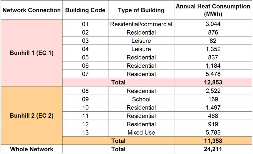
CIBSE Technical Symposium, Sheffield, UK 25-26 April 2019

the running of the trains, with the majority of heat being traced back to braking frictions
and other mechanical losses. With the recent increase in service levels on all lines,
and the expectancy of further rise in service in the future, it is likely that even more
heat will be available for recovery within the Underground network.

This opportunity is due to the London Clay soil surrounding the tunnel walls being an
insulator7, resulting in higher tunnel air temperatures. This is highlighted in Table 1,
which shows the average temperatures of the extracted air from a ventilation shaft in
Islington for the different seasons of the year, as provided by Islington Borough Council
(written communication, October 2018). By exploiting this opportunity, cooling is also
delivered to the Underground, which is equally beneficial.

 Table 1 – Measured minimum, maximum and average temperatures in a ventilation shaft in
 Islington (written communication, October 2018).

 2. Bunhill Heating Scheme
Within the context of fuel poverty and high rates of carbon-based heating in London,
the Bunhill Heat Network was an initiative from Islington Council to provide locally
produced lower cost and greener heat to warm nearby housing estates and service
buildings. The main concept behind the first phase of the project, also referred to as
Bunhill 1, was to use a gas-fired CHP system, which produces both electricity and
heat, linked to a heat distribution network in order to supply heating for the local
community. The Islington Council’s GIS system8 shows that 788 homes within three
housing estates and one residential building are being supplied with heat from the
network, which also feeds another four commercial buildings and two leisure facilities
in Islington.

In an effort to further expand the supply of low cost and low carbon heat to its residents,
Islington Council started to research potential extensions to the Bunhill Scheme, which
led to the opportunity of developing a waste heat recovery system based on heat
capture from the London Underground, in a partnership with Transport for London
(TfL) and the GLA. This project is the first of its kind in Europe and is part of the EU
CELSIUS Project. The decision to use waste heat sources is also related to the
decreasing carbon efficiency of CHP systems due to the decarbonisation of electricity
in the UK.

The extension, also referred to as Bunhill 2, will collect heat from a ventilation shaft on
the Northern Line of the Underground network. The heat will then be upgraded using

 Page 4 of 15
CIBSE Technical Symposium, Sheffield, UK 25-26 April 2019

a heat pump before being transferred into the DHN, which will be extended to connect
the new buildings to the ventilation shaft. Two CHP engines will also be added to the
system so as to provide resilience and flexibility to the heat network. The scheme is
expected to provide heating to 455 dwellings in 5 building blocks of local housing
estate and a local primary school. A new mixed use building complex that is currently
being developed will also be connected to Bunhill 2, adding 720 residential units, a
160-bed student accommodation and a 125-bed hotel, as well as areas for offices,
retail and restaurants as new end users of the network.

 Table 2 – Details of all buildings to be connected to the Bunhill District Heating Scheme.

Table 2 shows the heating demand and type of use for all the buildings that are
connected to Bunhill 1, and those which will be connected to Bunhill 2 after the
extension of the network is completed. The development of Bunhill 2 will shed light on
how London can become a truly smart city, showing how DHNs can be fundamental
in future smart energy infrastructures, both at district and ultimately city levels, by
allowing the capture of urban waste heat.

 3. Network Components
In order to understand the operation of the Bunhill Heating Scheme, it is essential to
bear in mind the capacities of the heat sources and the design parameters of the
network components, as shown in Figure 2. The Bunhill 1 Energy Centre comprises a
1.9 MWe/2.3 MWth gas fired CHP and a 115 m3 thermal store. The network currently
has flow and return temperatures of respectively 95°C and 75°C.

 Page 5 of 15
CIBSE Technical Symposium, Sheffield, UK 25-26 April 2019

 Figure 2 – Schematic of the Bunhill Heating System, considering both DHNs, Bunhill 1 and 2.

Bunhill 2 will involve an Energy Centre with an annual average heat output of 1,033
kWth, with 780 kW of heat being recovered from the ventilation shaft and then
upgraded by a two-stage heat pump, which will add the remaining 253 kW to the heat
that is delivered to end users through the DHN. The two CHP units, each with an
output of 237kWe/372kWth, will power the heat pump and also add resilience and
flexibility to Energy Centre 2, although its heat output could be dumped if unneeded.
A thermal store of 77.5 m3 will also be installed in order to add flexibility, helping to
manage peak demand. As shown in Table 1, the air that exhausts through the
ventilation shaft has temperatures varying from around 18°C to 28°C. Thus, the first
water loop, which transports the heat from the vent shaft to the heat pump, will also
work with flow and return temperatures that vary according to the season of the year.
The expected operating flow and return temperatures throughout the year vary from
11 to 18°C and 6 to 13°C, respectively. The reasons and impacts of these varying
water temperatures to the system’s cooling and heating duties will be further

 Page 6 of 15
CIBSE Technical Symposium, Sheffield, UK 25-26 April 2019

addressed in this paper. After Bunhill 1 and 2 are connected, the overall flow and
return temperatures will be of 75°C and 55°C, respectively.

As this paper aims to research the novelty related to the system, only the Bunhill 2
network will be investigated, focusing on the first trial to recover waste heat from the
London Underground. In order to analyse the expected operation of Bunhill 2, this
paper will consider the main components that make up the system for recovering
waste heat from railway tunnels.

 3.1. Heat Exchanger
The first stage of the system involves capturing the heat generated on Northern Line,
which is done by placing an air-to-water heat exchanger in the City Road ventilation
shaft. The heat exchanger used for this waste heat recovery system is a fan coil unit.
The ventilation shaft has been adapted by TfL in order to accommodate the heat
recovery heat exchanger. This involved building a head house where the coils were
installed and upgrading the variable speed reversible fan within the ventilation shaft.
The additional fan power required to overcome the pressure drop of the coils is very
little compared to the heat output that is generated. Even if a low fan efficiency of 50%
is considered, the additional power required would be of only 19.5 kW. The
calculations were based on Equation 19 and considered a design pressure drop of
138.9 Pa and an air flow of 70 m3/s.

 m3
 fan total pressure (Pa) × volumetric airflow � s � × 100
 ( ) = (1)
 fan efficiency (%)

The reversible fan enables the system to work in both Extract and Supply modes. The
benefits of operation in these two modes have been previously investigated by Davies
et al.6, and consists of reversing the flow direction of the fan, allowing the system to
operate by either extracting hot air from the Underground, which can then be used to
warm the water in the coils, or using ambient air, which would be cooled by the coils
and then supplied to the Underground, with the heat extracted being recovered by the
heat exchanger. Extract mode would be used during the colder months of the year,
when the heat demand is at its peak and heat can be collected at temperatures
between 18 and 25°C (excluding the summer months), as indicated in Table 1. When
in Supply mode, the cooled air would be used to supply cooling to the Underground
during the summer, with ambient air as the heat source, at an average temperature of
approximately 17°C10. This would lead to maximum flow and return temperatures in
the first water loop of, respectively, 18°C and 13°C. The system would not operate in
Extract mode during summer, although by doing so the water could reach even higher
temperatures. Figure 3 shows a schematic of the ventilation shaft and the head house,
showing the coil heat exchanger and the reversible fan.

 Page 7 of 15
CIBSE Technical Symposium, Sheffield, UK 25-26 April 2019

 Figure 3 – Schematic of the heat exchanger and the ventilation shaft of the Bunhill Energy
 Centre 2.

The design parameters of the heat exchanger have been selected to ensure it meets
the requirements of both the heat supplier and end users. Table 3 shows the design
parameters of the fan coil heat exchanger for three different operations, based on a
UA value of 164 kW/K, considering air on coil temperatures of 18°C, 20°C and 25°C.

 Fluid Air
 Water Temperature Air Temperature
 Operating Capacity
 Flow (°C) Flow (°C)
 Mode (kW)
 (kg/s) (m³/s) On Off
 On Air Off Air
 Coil Coil
 1 778 37.2 6 11 70 18 9
 2 780 37.2 8 13 70 20 11
 3 784 37.2 13 18 70 25 16
 Table 3 – Design parameters for the air-to-water fan coil heat exchanger in Extract mode.

The coils have an average operating cooling duty of 780 kW and consist of 6 modules
with 6 rows of copper tubes, resulting in a total of 36 rows of tubes - comprising the
coil heat exchanger. The coils were built up in modules to make maintenance simpler
and minimise downtime for cleaning. The tubes have a 12 mm diameter with fin
spacing of ¼ inch (approximately 6 mm), and a thickness of 0.18 mm. The fins were
designed to provide adequate spacing in order to avoid the use of filters, which can
be applied to prevent fouling but require regular cleaning and increase the potential
fire hazard. Recent research11 has proven that fouling effects can be minimised and

 Page 8 of 15
CIBSE Technical Symposium, Sheffield, UK 25-26 April 2019

filters avoided as long as the coil has a wide fin spacing of at least ¼ inch
(approximately 6 mm).

 3.2. Heat Pump
Following the heat capture in the ventilation shaft, the first water loop will transport the
recovered heat to a two-stage water to water heat pump, which was designed based
on the flow and return DHN temperatures of 75°C and 55°C, respectively. For district
heating purposes, as the evaporator and the condenser operate with a large
temperature difference, deploying single-stage heat pumps could lead to lower
compression efficiency and decrease the overall system performance12. Two-stage
compression represents a more flexible system, being able to operate at different
capacities, and with greater efficiency. One advantage is that it allows intercooling,
which decreases the necessary work input to the compressors, delivering high
temperature lifts with a high Coefficient of Performance (COP)13. The flash intercooler
also improves the efficiency of the system by allowing flash gas to be removed before
the refrigerant enters the evaporator, increasing its heat transfer rate. The two-stage
heat pump installed at Bunhill 2 operates differently according to the season of the
year, due to the varying temperatures of its heat source. Table 4 shows the design
parameters of the two-stage heat pump for the three different operating modes
established in Table 3.

 Operating Operating Operating
 Design Parameters
 Mode 1 Mode 2 Mode 3
 Cooling Duty - Qe (kW) 778 780 784
 First Loop Water Flow Temperature (°C) 11 13 18
 First Loop Water Return Temperature (°C) 6 8 13
 Heating Duty - Qc (kW) 1042 1033 1012
 DHN Flow Temperature (°C) 55 55 55
 DHN Return Temperature (°C) 75 75 75
 Estimated Shaft Power (kW) 264 253 228
 Estimated Electrical Consumption (kW) 286 275 248
 Cooling COP 2.72 2.84 3.16
 Heating COP 3.64 3.76 4.08
 Table 4 – Design parameters for the two-stage heat pump installed at Bunhill 2.

The two-stage heat pump uses R717 (ammonia) as a refrigerant. The low stage
includes a 25 bar compressor that can run at a wide range of capacities in order to
accommodate the variation in ventilation temperatures exhausted from the LU shaft.
The high stage includes two 50 bar compressors, which can also accommodate
varying capacity, while maintaining the desired outlet water temperature at 75°C. The
heated water from the first water loop will deliver heat to the heat pump’s evaporator,
with an approach temperature (ΔT) of 5°C, however, the cooling duty increases
slightly, as higher temperature water enters the evaporator14, to between 778 kW and

 Page 9 of 15
CIBSE Technical Symposium, Sheffield, UK 25-26 April 2019

784 kW, with an annual average of 780 kW. By varying the cooling duty, the power
input to the compressors can be minimised without compromising the design outlet
temperatures. This results in higher COPs as cooling duty is increased, with an annual
average COP of 3.76. There are 5 shell and plate heat exchangers within the heating
circuit, namely the flooded evaporator, a condenser, a subcooler and two
desuperheaters. Figure 4 shows a schematic of the two-stage water to water heat
pump installed at the Energy Centre of the Bunhill 2 heat network.

 Figure 4 – Schematic of the two-stage heat pump of the Bunhill Energy Centre 2.

 3.3. Thermal Storage
In order to provide flexibility, a thermal storage tank filled with 77.5 m3 of water will be
installed at Bunhill 2. Storing thermal energy is crucial to manage peak demand,
securing the reliability of the system when it is most requested. The thermal store also
avoids short cycling of the heat pump, enhancing its efficiency, since frequent
start/stop operation can harm the system’s reliability and increase its need for
maintenance.

 3.4. Heat Distribution Pipework
The heat distribution network will have an approximate length of 2.4 km and will utilise
two parallel insulated pipes, for the flow, i.e. heat delivery, and return water streams.
The flow and return temperatures are 75°C and 55°C, respectively, and water will
leave the heat pump outlet at a design flow rate of 37.2 kg/s. The network has different
pipe diameters, varying from DN 80 for local building connections to DN 250 for the
main flow/return pipes, which distribute the heated water from the heat sources to local
circuits, which feed one or more buildings connected to the network. Figure 5 shows
an overview map of the existing Bunhill 1 network and the proposed Bunhill 2,
including the heat distribution pipework, the heat sources and local buildings, which
are either already connected, or are proposed to be connected to the DHN in the
future. The building codes adopted in Table 2 will be used to identify each of the

 Page 10 of 15
CIBSE Technical Symposium, Sheffield, UK 25-26 April 2019

connected buildings on the map. Energy Centre 1 (EC1) corresponds to the Bunhill 1
CHP unit, whilst the Energy Centre 2 (EC2) represents the site where heat will be
captured from the City Road ventilation shaft, and also includes the heat pump and
the two CHP units.

 Figure 5 - The existing and planned heat networks for Bunhill 1 (red) and 2 (orange), adapted
 from Islington Council’s GIS System.8

 4. Benefit Analysis
In addition to introducing the technical heat delivery solution proposed for Bunhill 2,
the expected benefits of the scheme have been evaluated in relation to the operating
costs and carbon emissions. A spreadsheet based model was developed and used to
assess the benefits in terms of carbon and cost savings. The following analysis aims
to provide a high-level appraisal of the system’s benefits based solely on energy input
costs and carbon emissions related to heat delivered, and does not include any other
operational costs, such as for staff support and maintenance. The analysis compares
a scenario where all the heat demand is met by heat pumps to the previous heating
method based entirely on gas boilers that supply communal heat networks, which feed
the blocks of flats within each of the buildings. The calculations were based upon the
following assumptions:

 • A design life of 25 years (2019-2043) for the system;
 • Gas boiler efficiency of 80% for the existing communal boilers15;

 Page 11 of 15
CIBSE Technical Symposium, Sheffield, UK 25-26 April 2019

 • Carbon emission factors of 0.184 kgCO2e/kWh for natural gas and 0.145
 kgCO2e/kWh for electricity, which are based on the average of projections for
 long-run marginal factors for the design life of the system16;
 • Retail fuel prices of 3.89 p/kWh for natural gas and 14.22 p/kWh for electricity,
 considering the average of central projections for the design life of the system
 and a commercial/public sector tariff16;
 • Heat distribution losses of 10% for the primary network, which represent a
 reasonable assumption as primary losses vary from 3% to 11% depending on
 the type of heat network17.

Using these assumptions and the heat demand of the buildings connected to Bunhill
2, as shown in Table 2, the expected annual carbon and cost savings of a heat pump
based waste heat recovery system were calculated and compared to a gas boiler
based communal heating system.

 Energy Consumption
 Technology Efficiency/COP Heat Demand (MWh) Annual Energy Spent (MWh)
 Gas Boilers 80% 14,198
 11,358
 Heat Pump 3.76 3,323
 Carbon Savings
 Carbon Factor Annual Savings
 Technology Emissions (tCO2e)
 (kgCO2e/kWh) (tCO2e) %
 Gas Boilers 0.184 2,615
 2,133 82%
 Heat Pump 0.145 482
 Cost Savings
 Energy Tariff Annual Savings
 Technology Costs (£)
 (p/kWh) £ %
 Gas Boilers 3.89 552,283
 79,778 14%
 Heat Pump 14.22 472,505
 Table 5 – Calculated annual carbon and cost savings of a heat pump system as opposed to
 communal gas boilers.

The results of the analysis can be seen in Table 3, which shows that a heat pump
based system results in yearly carbon savings of 2,133 tCO2e, a decrease of 82% in
emissions, showing how waste heat recovery systems can help reducing the carbon
footprint associated with heating. This is due to the high energy efficiency of heat
pumps and the similar carbon factors for natural gas and electricity, which has
considerably decarbonised in recent years and should keep on decarbonising in the
future. The cost analysis results demonstrated how heat pumps can lead to annual
savings of £79,778 or 14%, which indicates waste heat recovery systems based on
heat pumps can be financially attractive, even though the considered electricity tariff
is 3.66 times more expensive than the tariff used for natural gas. The financial benefits
related of the scheme could be even greater if incentives are taken into account. The
application of a RHI payment of 2.69p/kWh, equivalent to the tariff applied to air-source

 Page 12 of 15
CIBSE Technical Symposium, Sheffield, UK 25-26 April 2019

heat pumps18, would result in an extra gain of £305,530, leading to overall savings of
£385,308 or 70%.

 5. Conclusion
The results obtained show the importance of investing in waste heat recovery systems,
as they can lead to significant carbon savings compared to conventional heating
methods and could become a key technology in fighting Climate Change. Despite
leading to operational cost savings, the conducted economic assessment did not
consider the capital costs related to heat pumps or the utilisation of the other heat
sources within the Energy Centre, which can impact the financial performance of the
scheme considerably.

Even though the costs of implementing district scale heat pumps are known to be high,
it is anticipated that they might become more attractive in the near future. As their
deployment becomes more popular, the capital costs related to waste heat recovery
tend to become lower. In addition, as natural gas reserves diminish over the next
decades and possible new carbon taxes are introduced, gas prices are likely to rise,
making heat pumps a viable alternative for heating. Results also showed how the
simple application of the RHI tariff for air-source heat pumps can increase the financial
benefits of the scheme and indicated how the introduction of carbon saving incentives
by the government could be an important policy to promote the use of low-carbon heat.

Further studies on the Bunhill Heating Scheme will be undertaken as part of a PhD
project, which will study the overall system particularly with regard to its technical and
financial performance. Bunhill 2 is expected to become operational in 2019. The study
will involve investigating the network components and their performances in detail,
comparing the design performance with the actual operation of the system. The
benefits of the system will also be looked into in more detail, considering seasonal
variations, capital costs and other operational costs and issues, as well as any other
challenges that might be encountered after Bunhill 2 starts running.

 6. References

(1) Committee on Climate Change (CCC). Reducing UK emissions – 2018 Progress
 Report to Parliament. Available from: https://www.theccc.org.uk/tackling-climate-
 change/reducing-carbon-emissions/how-the-uk-is-progressing/ [Accessed 30th
 October 2018].

(2) Department for Business, Energy & Industrial Strategy (BEIS). Heat Networks
 Investment Project, Introduction to the Scheme. Available from:
 https://www.gov.uk/government/publications/heat-networks-investment-project-
 hnip-scheme-overview [Accessed 21st November 2018].

 Page 13 of 15
CIBSE Technical Symposium, Sheffield, UK 25-26 April 2019

(3) European Environment Agency (EEA). Renewable energy in Europe 2017.
 Europe. Available from: https://www.eea.europa.eu/publications/renewable-
 energy-in-europe [Accessed 28th October 2018].

(4) Greater London Authority (GLA). London Environment Strategy. Available from:
 https://www.london.gov.uk//what-we-do/environment/london-environment-
 strategy [Accessed 30th October 2018].

(5) The Association for Decentralised Energy (ADE). Market Report: Heat Networks in
 the UK. Available from: https://www.theade.co.uk/resources/publications/market-
 report-heat-networks-in-the-uk [Accessed 4th November 2018].

(6) Davies G, Boot-Handford N, Grice J, Dennis W, Rami R, Nicholls A, Maidment GG.
 Metropolitan Integrated Cooling and Heating. ASHRAE Winter Conference, Las
 Vegas, USA. ASHRAE, 2017.

(7) Duffy S. Opportunities to Utilise Transport for London’s Secondary Heat Sources.
 CIBSE Technical Symposium, London, UK. CIBSE, 2018.

(8) Islington Council. Islington Council’s GIS System. Available from:
 http://mapapp.islington.gov.uk/mapthatol/Login.aspx?user=public [Accessed 16th
 November 2018].

(9) Jones WP. Air Conditioning Engineering. Edward Arnold, 1985. 421-480.

(10) Meteorological Office (Met Office). Islington Climate Information. Available from:
 https://www.metoffice.gov.uk/public/weather/climate/gcpvjttwz [Accessed 23rd
 October 2018].

(11) Maidment G, Baig S, Perris D, Boot-Handford N, Paurine A, Gilbey M, Wegner
 M, Dragoni F. An Investigation of Cooling Unit Performance on the London
 Underground Railway Network. CIBSE Technical Symposium, Edinburgh, UK.
 CIBSE, 2016.

(12) Kwon O, Cha D, Park C. Performance evaluation of a two-stage compression
 heat pump system for district heating using waste energy. Energy. 2013, 57: 375-
 381.

(13) Arpagaus C, Bless F, Schiffmann J, Bertsch SS. Multi-temperature heat pumps:
 A literature review. International Journal of Refrigeration. 2016, 69: 437-465.

(14) Stoecker WF, Jones JW. Refrigeration and air conditioning. McGraw-Hill, 1982.
 281-295.

(15) BRE Group. Standard Assessment Procedure, version 10 (SAP 10). Available
 from: https://bregroup.com/sap/sap10 [Accessed 26th November 2018].

 Page 14 of 15
CIBSE Technical Symposium, Sheffield, UK 25-26 April 2019

(16) Department for Business, Energy & Industrial Strategy (BEIS). Green Book
 supplementary guidance: valuation of energy use and greenhouse gas emissions
 for appraisal. Available from: https://www.gov.uk/government/publications/
 valuation-of-energy-use-and-greenhouse-gas-emissions-for-appraisal [Accessed
 13th February 2019].

(17) Department of Energy & Climate Change (DECC). Assessment of the costs,
 performance and characteristics of UK heat networks. Available from:
 https://www.gov.uk/government/publications/assessment-of-the-costs-
 performance-and-characteristics-of-uk-heat-networks [Accessed 26th November
 2018].

(18) Office of Gas and Electricity Markets (Ofgem). Non-Domestic Renewable Heat
 Incentive (RHI). Available from: https://www.ofgem.gov.uk/environmental-
 programmes/non-domestic-rhi [Acessed 28th November 2018].

 Acknowledgments
The authors would like to acknowledge the support from London South Bank
University, Transport for London and the Engineering and Physical Sciences
Research Council (EPSRC) sponsored project Low Temperature Heat Recovery and
Distribution Network Technologies (LoT-NET). The authors are also grateful to
Rodrigo Matabuena, Stephen Mirkovic, Graeme Low and James Wilson of the London
Borough of Islington for their support in providing valuable information for this project.

 Page 15 of 15
You can also read