Effect of Al-Zn Alloy Coating on Corrosion Fatigue Behavior of X80 Riser Steel - MDPI
←
→
Page content transcription
If your browser does not render page correctly, please read the page content below
materials
Article
Effect of Al–Zn Alloy Coating on Corrosion Fatigue
Behavior of X80 Riser Steel
Zhongying Han 1 , Xiaoguang Huang 2, * and Zhicheng Yang 3, *
 1   School of Petroleum Engineering, China University of Petroleum (East China), Qingdao 266580, China;
     hzy_0218@163.com
 2   College of Pipeline and Civil Engineering, China University of Petroleum (East China), Qingdao 266580,
     China
 3   Guangzhou University-Tamkang University Joint Research Centre for Engineering Structure Disaster
     Prevention and Control, Guangzhou University, Guangzhou 510006, China
 *   Correspondence: huangupc@126.com (X.H.); cs.yeung@e.gzhu.edu.cn (Z.Y.)

 Received: 15 April 2019; Accepted: 5 May 2019; Published: 9 May 2019

 Abstract: This paper presents a corrosion fatigue cyclic failure test for X80 steel, which has arc sprayed
 with an Al–Zn coating in natural seawater under different stress levels. We found that the Al–Zn
 coating can significantly improve the corrosion fatigue resistance and slow the crack initiation of X80
 steel. The effect of the Al–Zn coating on the corrosion fatigue crack initiation is mainly attributed to
 its physical isolation, cathodic protection and residual prestress while the effect on crack propagation
 is due to its inhibition of the formation and evolution of secondary cracks. Moreover, according to
 the test results, a new life prediction model for corrosion fatigue based on the damage evolution
 law is proposed and the effect of corrosion–fatigue coupling damage in the proposed model is
 also considered.

 Keywords: corrosion fatigue; arc spray; Al–Zn coating; crack initiation; crack propagation

1. Introduction
      As a piece of key equipment for deep-sea oil exploration, the safety and reliability of drilling risers
have attracted an increasing amount of attention [1]. The riser always undergoes large reciprocating
deformation under the actions of the currents and waves in addition to suffering from the corrosion
effect of seawater. Furthermore, corrosion fatigue is one of the main failure modes for these slender
flexible structures [2–4]. The failure period of corrosion fatigue is generally divided into three stages:
Crack nucleation, fatigue crack propagation, and rupture. The first two stages determine the service
life [5,6]. Corrosion fatigue failure preferentially initiates from corrosion pits [7,8] due to the anodic
dissolution inside the pits accelerated by mechanochemical effects [7] and irreparable damage caused
by corrosion products [8]. Although the mechanism of fatigue crack propagation is very complicated
and it is difficult to generalize this mechanism, the effect of corrosion on crack propagation is definitely
not negligible [9–11]. Therefore, the methods for inhibiting corrosion to extend the corrosion fatigue
life has been widely adopted, such as surface enhancement by laser [12], low plasticity burnishing [13]
and cathodic protection.
      Cathodic protection has been widely used for the corrosion protection of metallic materials,
which is mainly implemented by a forced current and a sacrificial anode. Compared with a forced
current, it is easy to operate a sacrificial anode and it is not affected by the environment. Sacrificial
anode protection can be realized by thermally spraying the coating, cold spraying the coating and
creating cathodic polarization with sacrificial anodes connected to the specimen, thereby improving the
corrosion resistance of the substrate. Aluminum, zinc and their alloys are commonly used as cathodic

Materials 2019, 12, 1520; doi:10.3390/ma12091520                               www.mdpi.com/journal/materials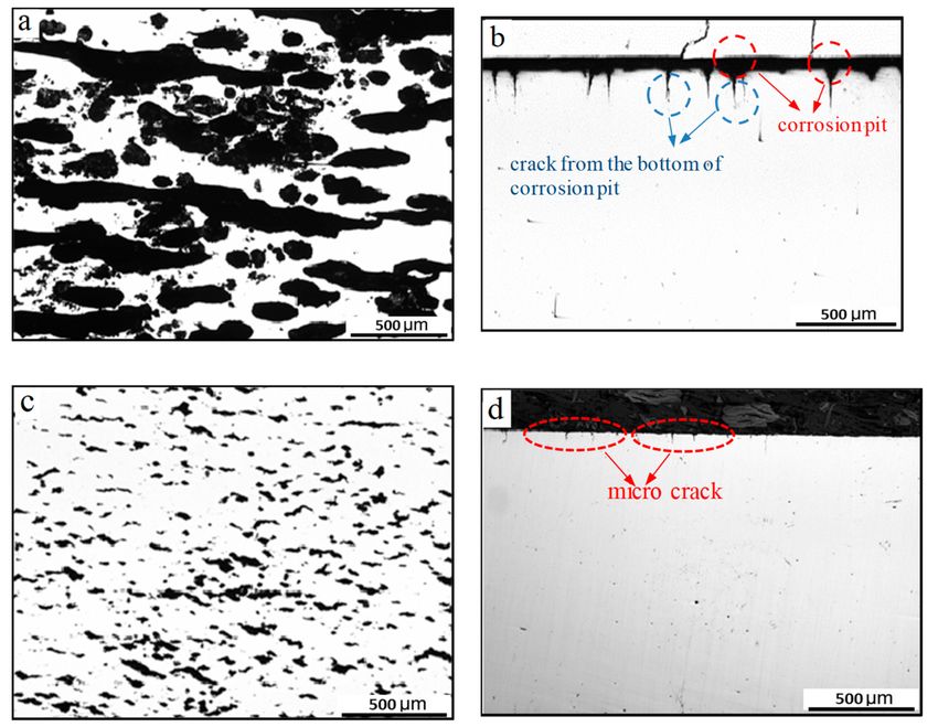
Materials 2019, 12, 1520                                                                           2 of 11

protection materials due to their relative good corrosion resistance and sufficient negative potential
that make them suitable for harsh environments [14]. Simultaneously, the techniques of anodic coating,
such as cold spraying, thermal spraying, and hot-dipping spraying, and their potential applications
have been greatly promoted. Furthermore, their efficacy - and suitability for different environments
have also attracted a wide range of research interests. Diab studied the corrosion and corrosion fatigue
behavior of magnesium (3% Al–1% Zn) extrusion with a pure aluminum cold spray coating and
found that the pure Al coating provided significant corrosion protection for AZ31B in 5% NaCl fog
environment despite the unsatisfactory protection provided against corrosion fatigue [15]. Meanwhile,
Al 7075 deposited on AZ31B alloy significantly increased corrosion resistance and lengthened the
fatigue life compared to the uncoated specimen in a corrosive environment [16]. Okabe [17] found
that the corrosion resistance and corrosion fatigue resistance of steel coated with Zn–Al (–Si and–Mg)
and Zn (–Mn,–Cr and–Ni) alloys by a hot-dipping spray improved after the treatment although this
depended on the coating conditions. Tachibana [18] compared the influences of a fine Zn and Zn–Al
alloy double coating created by hot dipping on the corrosion resistance of steel in coastal areas and
found that the life of the Zn–7Al alloy-coated steel was four times longer than that of the Zn–coated
steel. Ahnia [19] detected the corrosion reduction of the arc-sprayed aluminum coatings on steel
in a simulated marine environment and the tests showed that iron dissolution through the coating
decreases with an increase in the annealing temperature. Zhao [20] found that the thermal spraying
aluminum coating could significantly improve the corrosion fatigue life of the steel substrate according
to the corrosion fatigue crack propagation experiments of aluminum coated X80 steel in 3.5 wt % NaCl
solution. In addition to the aluminum and Zinc coating, Zinc–chromium coating was also used for the
corrosion and corrosion fatigue protection of mild steel [21]. Villalobos-Gutiérrez et al. [22] evaluated
the effect of WC–10Co–4Cr thermal spraying coating by high-velocity oxygen fuel deposition (HVOF)
on the fatigue and corrosion properties of AA6063–T6 aluminum alloy. The results showed that the
HVOF thermal spray process gave rise to significant gains in fatigue life in comparison with the
uncoated substrate when testing was carried out both in air and in a 3 wt % NaCl solution. Among the
three anodic coating techniques, thermal spraying is the most highly developed and widely applied
in marine engineering. Long-time practical applications also showed that thermal spraying coatings
could effectively protect marine structures from corrosion [23–25].
      Anodic coatings protect marine steel from corrosion and corrosion fatigue by physical isolation
and cathodic protection. Therefore, the spraying qualities, such as the porosity and electrochemical
activity of coatings, significantly determine the protection effect [26,27]. Meanwhile, most marine
structures, such as deepwater risers, are subject to a severe environment and random bending loads [28].
The effects of anodic coatings on corrosion fatigue behavior are essential for the applications in marine
structures. Furthermore, the mechanism related to the improvement of corrosion fatigue behavior
due to anodic coatings requires more indepth study and experimental support in view of the material
and environment dependence of corrosion fatigue. In this paper, the corrosion fatigue tests of the X80
riser steel in natural seawater are carried out for studying the effect of Al–Zn coating by arc spraying
on the corrosion fatigue life. Furthermore, the mechanism related to the coating -inhibiting the crack
initiation and propagation is studied by fracture analysis technology.

2. Corrosion Fatigue Test
      The X80 steel used in the test contained (wt %) 0.048% C, 0.195% Si, 1.717% Mn, 0.012% P, 0.002%
S, 0.219% Cr, 0.184% Mo, 0.268% Ni, 0.023% Al and the remainder was Fe. The yield strength σs and
tensile strength σb of X80 steel were 680 MPa and 710 MPa, respectively, which indicated that the X80
steel had a better ability to resist deformation. The cylindrical specimens were obtained from an X80
steel bar (Φ24 mm) by wire-cutting and fine grinding for smoothness as shown in Figure 1.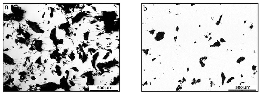
Materials 2019, 12, 1520                                                                           3 of 11

                           Figure 1. Dimension of smooth cylindrical specimen (mm).

     Before the arc spraying, the rust on specimens needs to be removed. The surface of specimens
was blasted by corundum at a pressure and distance of 0.6 MPa and 150 mm, respectively, to achieve
the surface roughness of 50–80 µm. After that, the Al–Zn alloy wire (85% Al, 15% Zn) with a 2 mm
diameter was used in a CMD–AS1620 arc spraying system (Xindi, Beijing, - China), while the distance
between the nozzle and the substrate was kept at 150 mm. During the spraying, the stagnation pressure
and the wire feed rate used in the spraying system were set as 0.7 MPa and 10 cm/min, respectively,
and the coating thickness was kept at 500 ± 30 µm by finely adjusting the process parameters of the
spraying system. The hardness measurement at a load of 0.98 N shows that the average Vickers
hardness near the surface of the coated sample is 147.2 ± 3.6 HV, which is obviously lower than that
of the uncoated sample (241.3 ± 6.3 HV). An IPRE-SR200 surface roughness tester (Purui, Shenzhen,
Guangzhou, -China) is utilized to measure the coated surface, and the roughness results measured
from different positions are taken the average to eliminate the influence of error as much as possible.
The measured surface roughness of the coated sample is 63.5 ± 8.4 µm. The microstructure of the
coated specimen observed under an optical microscope is shown in Figure 2. The coating thickness
meets the pre-requirement according to the thickness measurement at three different locations. It can
be noted that the coating represents a pseudo two-phase alloy structure, within which the grey–white
part is the Al-rich phase and the grey-black part is the Zn-rich phase. Furthermore, grey–white phase
and grey–dark phase of the coatings stack alternately on the substrate in a wavy form. This is attributed
to the fact that the Al–Zn alloy undergoes a crystallization process from melting to cooling during
the preparation of the coating and the rapid solidification process prevents Al–Zn from completely
melting, which results in the presence of the two-phase structure.

                           Figure 2. Cross-section microstructure of coated specimen.

     To ensure that the Al–Zn alloy was well coated on the specimens, the microstructures and
elemental compositions of the coating were detected by observing the sectioning microstructures and
applying the electron microprobe analysis (EMPA) method (JEOL, Tokyo, Japan). The corresponding
results are shown in Figure 3. The electron microprobe scanned along the thickness of the coating
(Figure 3a) and showed the content distribution of Al and Zn (Figure 3b) in the coating. However,
there was a higher oxygen content somewhere in the coating along its thickness. This could be the
result of aluminum oxide inclusion in the coating when spraying.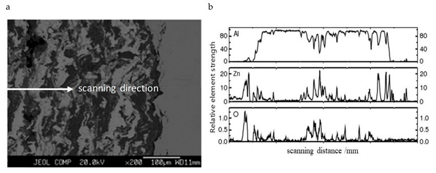
Materials 2019, 12, 1520                                                                                     4 of 11

                           Figure 3. EMPA analysis of (a) scanned image and (b) analysis results.

     For the facilitation of the corrosion fatigue failure test, a special seawater circulation system
(Figure 4) was designed to ensure there was a good interaction between the specimen and seawater
during the fatigue test. The seawater circulation system was composed of a storage box, a chamber,
a tube, a recycling pump, and a shower. The seawater was driven by the pump and sprays on the
specimen in the chamber before being collected by the storage box. The test section of the specimen
was wrapped in an absorbent fiber for good infiltration into the seawater. Finally, the corrosion fatigue
failure tests were carried out by a cardan low-frequency rotating bending fatigue testing machine
and four stress amplitudes (204 MPa, 272 MPa, 408 MPa, and 544 MPa) were used while the load
frequencies for each stress were set as 0.5 Hz and 2 Hz, respectively.

        Figure 4. Setup of circulation device of corrosion solution matching with fatigue testing machine.

3. Results and Discussion

3.1. Coating on Corrosion Fatigue Life
   Figure 5 shows the effect of stress amplitudes, load frequencies, and coating on the fatigue life in a
number of failure cycles. Figure 5a shows that when the load frequency is assigned to 2 Hz, the fatigue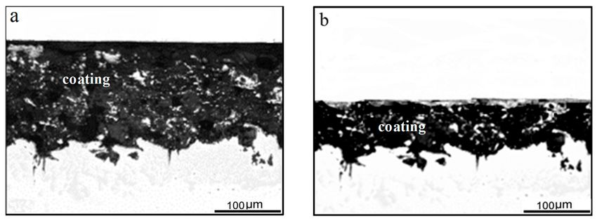
Materials 2019, 12, 1520                                                                                     5 of 11

life of both coated and bare X80 steel is shorter in the presence of corrosion. It also can be noted that
the corrosion fatigue life of the coated X80 steel is longer than that without coating and it decreases as
the stress amplitude increases. From Figure 5b, the number of corrosion fatigue failure cycles of the
X80 steels is relatively related to the load frequency and becomes smaller when there is a lower load
frequency. The effect of the coating on fatigue is not as remarkable as that on corrosion fatigue due to
the surface roughness being critical to fatigue crack initiation without the interaction of the corrosive
environment. Arc spraying slightly increases the size of the specimen and improves the prestress state
on the surface. However, the roughness of the coating surface makes it difficult to achieve a machining
accuracy of the uncoated sample, and to some extent, this accelerates the crack initiation at the surface.

      Figure 5. Comparison between fatigue and corrosion fatigue life in number of failure cycles: (a) Fatigue
      and corrosion fatigue life at f = 2 Hz and (b) load frequency on corrosion fatigue life.

3.2. Mechanism of Coating Improving Corrosion Fatigue Life
     Figure 6a,b shows the metallographic morphologies of corrosion and crack at the surface and
cross-section of the bare specimen under low stress (276 MPa) after 100,000 cycles at a frequency of 2 Hz.
From Figure 6a,b, it can be observed that a significant number of corrosion pits and some conspicuous
cracks in the bottom of the corrosion pit appear at the surface when the stress amplitude adopted in
the test is 276 MPa. However, when the stress amplitude increases to 522 MPa, there are no obvious
corrosion pits but numerous tiny cracks are formed at the surface and cross-section (Figure 6c,d) after
15,000 cycles. This could be that the specimen subjected to a higher stress amplitude has a shorter
fatigue life and the contact time between the specimen and corrosion solution is limited. There are no
obvious corrosion pits forming at the surface of the specimen.
     Obviously, the contribution of the corrosion to crack nucleation differs under different stress levels.
Stress softening is a common phenomenon at low cycle fatigue of the X80 steel due to its high yield
ratio. Plastic deformation caused by cyclic softening results in the regional material being easy to slip.
This forms the resident slip zone, resulting in a local preferential dissolution of material and fatigue
crack initiation [29]. As a result, the bare specimens are vulnerable to fractures under high-stress
conditions due to the existence of resident slip bands. Meanwhile, crack propagation also causes stress
release, which makes it difficult for the cracks in other regions to form or expand. This further explains
why the cracks under high-stress conditions are shorter and smaller from metallographic pictures.
     Figure 7 shows the surface metallographic morphology of the coated specimen after certain cycles.
Figure 7a shows the surface morphology under low-stress conditions (276 MPa) after 100,000 cycles at
a frequency of 2 Hz. It can be seen that a significant number of corrosion pits in black appear on the
coating surface, while the corrosion is significantly less than that in Figure 6a. Figure 7b shows the
surface morphology under high-stress conditions (552 MPa) after 50,000 cycles. At high-stress levels,
no obvious corrosion pits and corrosion fatigue cracks appear on the surface of the specimen.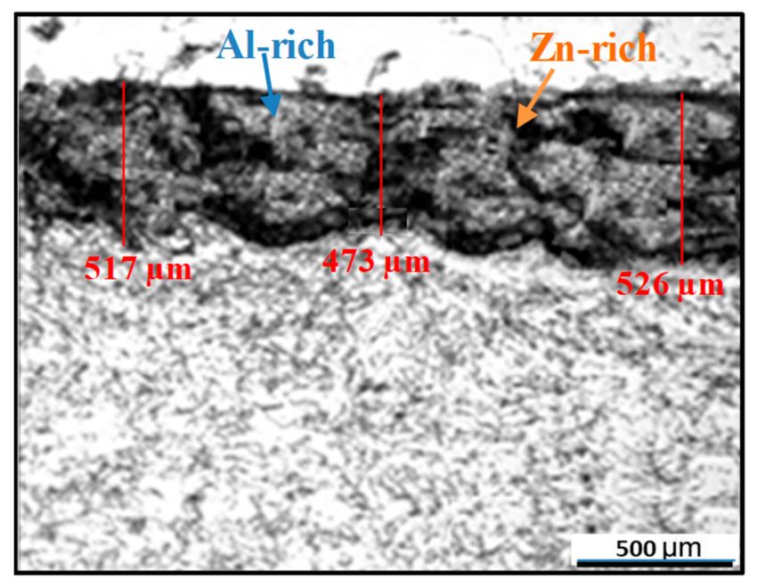
Materials 2019, 12, 1520                                                                                 6 of 11

      Figure 6. Metallography of bare specimen at the surface and cross-section after corrosion fatigue at
      2 Hz: (a,b) 276 MPa and (c,d) 552 MPa.

      Figure 7. Surface metallographic photographs of corrosion fatigue formation of coated specimen:
      (a) 276 MPa after 100,000 cycles and (b) 552 MPa after 50,000 cycles.

     Figure 8 depicts the microstructural changes in the coating after 300,000 and 400,000 cycles. It can
be seen that the thickness of the layer gradually reduces and the size of the pore in the coating also
increases. By comparing the crack initiation and fatigue life of bare and coated specimens, it is not
hard to determine that the arc spraying significantly inhibits the initiation of corrosion fatigue cracks.
The effects of the coating on fatigue crack initiation mainly lie in the following aspects, i.e., physical
isolation, cathodic protection, and residual stress at the surface made by sandblasting. The coating
acts as an isolating layer between the substrate and seawater until it consumes too much to achieve
complete physical isolation. The self-corrosion potentials of aluminum and zinc are both about −1.0 V,
and that of X80 steel before sandblasting is about −0.6 V in the seawater vs. a saturated calomel
electrode (SCE). Therefore, the coating provides the cathodic protection of the X80 as it acts as a
sacrificial anode during the corrosion fatigue process. Sandblasting before the arc spraying can cause
certain compressive stress on the surface, and a certain plastic deformation will occur on the surface of
the specimen when the compressive stress exceeds the yield strength of the material. It is believed that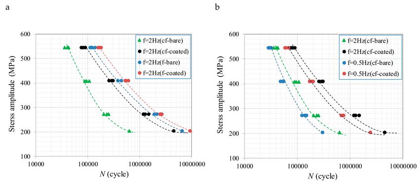
Materials 2019, 12, 1520 7 of 11
the compressive stress and compression plastic deformation can prevent fatigue crack initiation [30,31].
The rheological microstructure at the surface is protected from the isolation of the coating and the effect
of residual compressive stress and plastic deformation on the corrosion fatigue crack initiation are
brought into full play when the coating loses its complete isolation of the substrate from the seawater.
Figure 8. Metallographic microstructure of coatings: (a) After 300,000 cycles and (b) after 400,000 cycles.
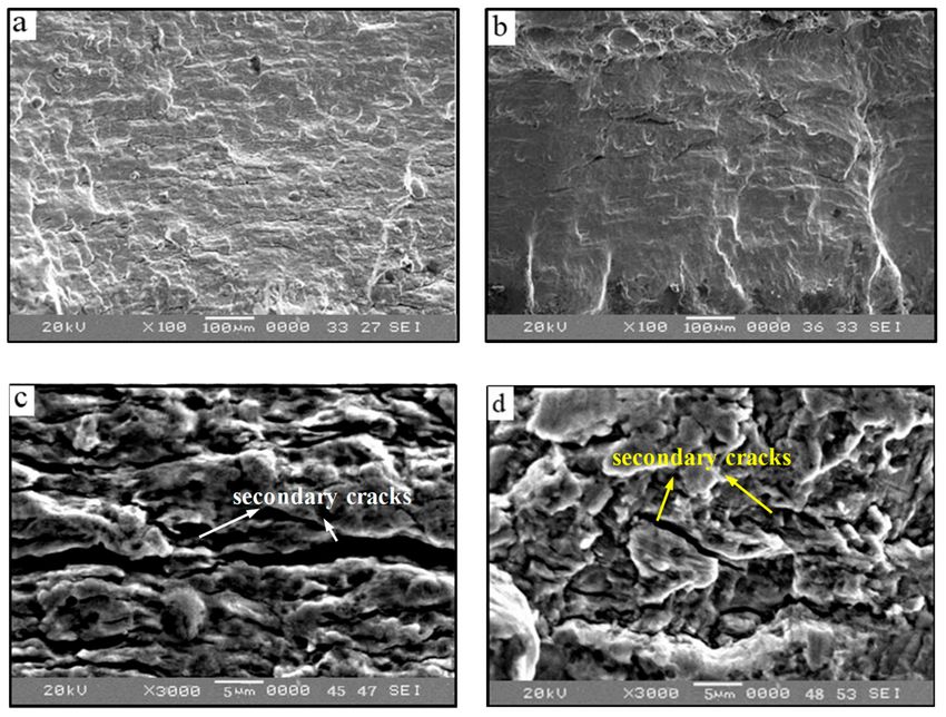
The most distinctive feature of crack propagation is the formation of fatigue striations.
The secondary cracks are closely related to the crack propagation and formation of corrosion fatigue
striations. Furthermore, the effect of the coating on fatigue crack propagation can be explained by the
formation and evolution of secondary cracks. Therefore, the mechanism of the Al–Zn coating on the
corrosion fatigue crack of X80 steel can be explained by comparing the formation of the corrosion
fatigue striation of bare steel and coated steel. Figure 9a,b shows the morphologies of the fracture
propagation zone of bare and coated specimens under high-stress conditions. There are innumerable
secondary cracks and corrosion products on the fracture surface of bare specimens, while the corrosion
and the number of secondary cracks are significantly less on the fracture surface of coated specimens.
The secondary crack striations of the bare and coated steels are observed more carefully in Figure 9c,d.
We found that the direction of the secondary crack striations is almost the same as that of the corrosion
fatigue striations. The main difference is that the secondary crack striation on the surface of bare
specimens is deeper than that on the coated specimens. Meanwhile, the fatigue striations of bare
specimens are less clear as they are covered in a layer of corrosion products. It can be concluded that
the existence of corrosion products aggravates the irreversibility of the grain boundary slip, which
leads to the accumulation of irreversible damage and promotes the propagation of secondary cracks.
Conversely, the coating provides cathodic protection and greatly reduces the corrosion and irreversible
slip at the crack tip. Therefore, the corrosion fatigue damage cannot easily accumulate and the crack
propagation is partly inhibited.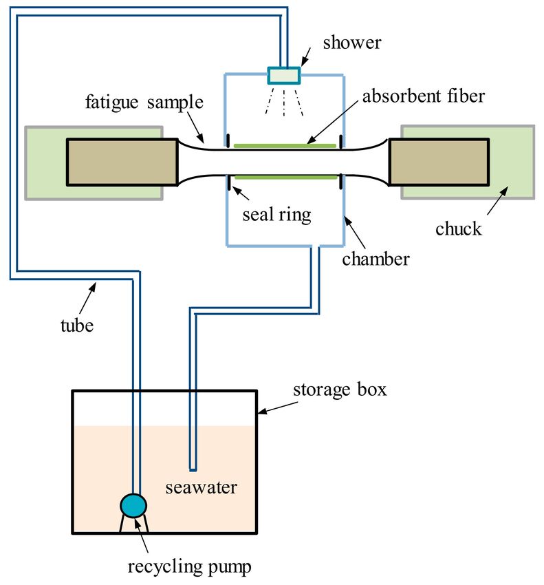
Materials 2019, 12, 1520                                                                              8 of 11

      Figure 9. Fracture morphology of crack propagation zone: (a,c) Corrosion fatigue striations and
      secondary cracks of bare specimen; and (b,d) corrosion fatigue striations and secondary cracks of
      coated specimen.

4. Discussion
     According to the damage mechanics, the corrosion fatigue is regarded as a process that results in
damage initiating and accumulating inside the material under the coupling action of the corrosion
environment and cyclic loading. Hence, the total evolution law of corrosion fatigue damage can be
expressed as follows [32]:
                                      dD     dDc    dDscc      dD
                                          =       +       + T0 f                                    (1)
                                      dt      dt      dt        dt
where D, Dc , Dscc and Df are the corrosion fatigue damage, corrosion damage, stress corrosion damage
induced by average stress, and fatigue damage caused by stress amplitude, respectively, t is time, N is
the number of cycles, and T0 is the period of fatigue loading.
     If the evolution law of corrosion damage and corrosion stress damage is adopted as follows:

                                         dDc   c0 + c1 (σ0 + σa )α
                                             =                                                            (2)
                                          dt       (1 − D)m

                                          dDscc           σ0 ζ

                                                = cscc         H0                                         (3)
                                           dt            1−D
where c0 is the damage accumulating factor in a stress-free state, m is the accumulating index of
corrosion damage, σ0 and σa are the average stress and stress amplitude, respectively, c1 (σ0 + σa )α is
the accelerating effect of stress on corrosion damage, α and ζ are constants related to the material, cscc
is the accumulating factor of stress corrosion damage, σscc is the nominal threshold stress of stress
corrosion, and Hm is the activation function of stress corrosion damage, which can be expressed as: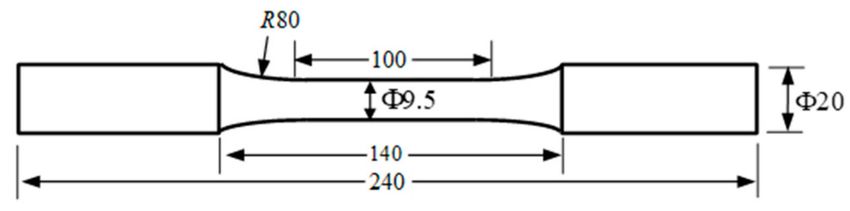
Materials 2019, 12, 1520 9 of 11
n {1−D σ γ σ
1−
σ0
scc 0
when 1−D > σscc
H0 = σ0 (4)
0
when 1−D ≤ σscc
where γ is a material constant.
When only the influence of cyclic stress amplitude is considered in the above-mentioned fatigue
damage model, the fatigue damage per cycle can be simplified as follows [33]:
!ξ
dDf σa
= (1 − D)−µ (5)
dN M ( σ0 )
where µ and ξ are the experimental constants and M(σ0 ) is a material parameter that is related to the
average stress. Therefore, the damage evolution law of corrosion fatigue can be written as:
!ξ
dD c0 + c1 (σ0 + σa )α σ0 ζ σa
−µ
= T0 + cscc T 0 H0 + ( 1 − D ) (6)
dN (1 − D)m 1−D M ( σ0 )
For the symmetrical rotating bending corrosion fatigue, the damage law can be simplified as:
!ξ
dD c0 σa
= T0 + (1 − D)−µ (7)
dN (1 − D)m M(σ0 )
By integrating Equation (7), the corrosion fatigue life N expressed by damage evolution is
obtained as: Z Dc
dD
N= ξ (8)
c0 T0 (1 − D)−m + (1 − D)−µ Mσ(a0)
D0
where D0 is the initial damage that is usually taken as 0 and Dc is the critical damage, which is taken as
one for simplicity.
The parameters µ, ξ, and M(σ0 ) can be determined according to the fatigue test. The evolution
life of the corrosion fatigue damage is determined using Equation (8) by adopting dD = ∆D = 0.001.
Figure 10 shows the regression results for the corrosion fatigue of the bare and coated samples at f = 2
Hz. It can be noted that there is good consistency between the test result and predicted results, which
indicates that the prediction model can provide reasonable predictions for corrosion fatigue life.
Figure 10. Regression results in corrosion fatigue damage evolution law.
5. Conclusions
This paper conducted an experimental investigation of the corrosion fatigue behavior of X80
steel with an Al–Zn coating. The effects of stress amplitude, load frequency and the presence of theMaterials 2019, 12, 1520 10 of 11
coating on the corrosion fatigue life of X80 steels were studied. A prediction model for predicting the
corrosion fatigue life was verified by the test results. We found that the Al–Zn coating can significantly
improve the corrosion fatigue life of X80 steel. The load frequency and the stress amplitude used in
the test significantly influence the corrosion fatigue life of X80 steel. The coating on X80 steel can
inhibit the initiation and propagation of the corrosion fatigue crack compared to X80 steel without a
coating. The effect from arc spraying the Al–Zn coating on fatigue crack initiation is mainly related
to the physical isolation, cathodic protection. and residual stress at surface made by sandblasting.
The effect of Al–Zn coating on crack propagation is mainly reflected in the inhibition of the formation
and evolution of secondary cracks. A new damage evolution law for corrosion fatigue is also proposed
to consider the accumulation mechanism of corrosion-fatigue coupling damage, which can provide
reasonable predictions for corrosion fatigue life compared to the test results.
Author Contributions: X.H. conceived and designed theory and experiments, and wrote the primary manuscript;
Z.H. contributed experiments and tools; Z.Y. provided feedback on the described experiments and the writing of
the manuscript. All authors contributed to the modifying of the manuscript.
Funding: This research was funded by the National Natural Science Foundation of China, grant number 51404286
and 51574270, the Fundamental Research Funds for the Central Universities of China, grant number 17CX02065,
and the China Scholarship Council (File No. 201806455016).
Conflicts of Interest: The authors declare no conflicts of interest.
References
1. Bai, Y.; Bai, Q. Subsea Pipelines and Risers; Elsevier: Oxford, UK, 2005.
2. Feng, G.; Thodla, R.; Evans, K.; Joia, C.; Baptista, I.P. Corrosion fatigue performance of duplex 2507 for
riser applications. In Proceedings of the ASME International Conference on Ocean, San Antonio, TX, USA,
14–18 March 2010; pp. 99–108.
3. Rus, D.; Hoppe, W.; Braisted, W.; Powar, N. Fatigue life prediction of corrosion-damaged high-strength steel
using an equivalent stress riser (ESR) model. Part II: Model development and results. Int. J. Fatigue 2009, 31,
1454–1463.
4. Pe’rez-Mora, R.; Palin-Luc, T.; Bathias, C.; Paris, P. Very high cycle fatigue of a high strength steel under
seawater corrosion: A strong corrosion and mechanical damage coupling. Int. J. Fatigue 2015, 74, 156–165.
[CrossRef]
5. Ostash, O.; Kostyk, E.; Makoviichuk, I.; Chepil, R. Initiation and growth of corrosion-fatigue cracks near
stress concentrators in V95pchT2 aluminum alloy. Mat. Sci. 1999, 35, 1–9. [CrossRef]
6. Huang, X.G.; Xu, J.Q. Pit morphology characterization and corrosion fatigue crack nucleation analysis based
on energy principle. Fatigue Fract Eng. Mater. Struct. 2012, 35, 606–613.
7. Huang, Y.H.; Tu, S.H.; Xuan, F.Z. Modeling and simulation of pit chemistry of 304 austenitic stainless steel
under applied stress in sodium chloride solution. Nucl. Eng. Des. 2013, 257, 45–52. [CrossRef]
8. Zhao, W.M.; Wang, Y.X.; Zhang, T.M.; Wang, Y. Study on the mechanism of high-cycle corrosion fatigue
crack initiation in X80 steel. Corros. Sci. 2012, 57, 99–103. [CrossRef]
9. Zhao, T.L.; Liu, Z.Y.; Du, C.W.; Sun, M.H.; Li, X.G. Effects of cathodic polarization on corrosion fatigue life of
E690 steel in simulated seawater. Int. J. Fatigue 2018, 110, 105–114. [CrossRef]
10. Wei, R.; Speidel, M. Corrosion Fatigue: Chemistry, Mechanics and Microstructure; National Association of
Corrosion Engineers: Houston, TX, USA, 1972.
11. Zhao, W.M.; Xin, R.W.; He, Z.R.; Wang, Y. Contribution of anodic dissolution to the corrosion fatigue crack
propagation of X80 steel in 3.5 wt. % NaCl solution. Corris. Sci. 2012, 63, 387–392. [CrossRef]
12. Mhaede, M. Influence of surface treatments on surface layer properties, fatigue and corrosion fatigue
performance of AA7075 T73. Mater. Des. 2012, 41, 61–66. [CrossRef]
13. Prevey, P.; Cammett, J. The influence of surface enhancement by low plasticity burnishing on the corrosion
fatigue performance of AA7075-T6. Int. J. Fatigue 2004, 26, 975–982. [CrossRef]
14. Ellor, J.A.; Young, W.T.; Repp, J. Thermally Sprayed Metal Coatings to Protect Steel Pilings: Final Report and Guide;
Transportation Research Board: Washington, DC, USA, 2004.Materials 2019, 12, 1520 11 of 11
15. Diab, M.; Pang, X.; Jahed, H. The effect of pure aluminum cold spray coating on corrosion and corrosion
fatigue of magnesium (3% Al–1% Zn) extrusion. Surf. Coat. Technol. 2017, 309, 423–435. [CrossRef]
16. Shaha, S.K.; Dayani, S.B.; Jahed, H. Influence of cold spray on the enhancement of corrosion fatigue of
the AZ31B cast Mg alloy. In Proceedings of the TMS 147th Annual Meeting & Exhibition Supplemental
Proceedings, Phoenix, AZ, USA, 11–15 March 2018; pp. 541–550.
17. Okabe, J.; Oki, T.; Tms, M.M.I.J. Corrosion and corrosion fatigue behavior of zinc alloy hot-dip coated steel.
In Proceedings of the 1st International Conference on Processing Materials for Properties, Honolulu, HI,
USA, 7–10 November 1993; pp. 581–584.
18. Tachibana, K.; Morinaga, Y.; Mayuzumi, M. Hot dip fine Zn and Zn–Al alloy double coating for corrosion
resistance at coastal area. Corros. Sci. 2007, 49, 149–157. [CrossRef]
19. Ahnia, F.; Demri, B. Evaluation of aluminum coatings in simulated marine environment. Surf. Coat. Technol.
2013, 220, 232–236. [CrossRef]
20. Zhao, W.M.; Zhang, T.M.; Xin, R.Z.; Wang, M.M.; Ai, H.; Sun, J.B.; Wang, Y. Effects of thermally sprayed
aluminum coating on the corrosion fatigue behavior of X80 steel in 3.5 wt. % NaCl. J. Ther. Spray Technol.
2015, 24, 974–983. [CrossRef]
21. Shaharuddin, S.A. An investigation into the corrosion behaviour of zinc and chromium metallic coating on
mildsteel substrate. Optoelectron. Integr. Circuits XV 2011, 8628, 356–360.
22. Villalobos-Gutiérreza, C.J.; Gedler-Chacóna, G.E.; Barbera-Sosa, J.G.; Piñeirob, A.; Staia, M.H.; Lesage, J.;
Chicot, D.; Mesmacque, G.; Puchi-Cabrera, E.S. Fatigue and corrosion fatigue behavior of an AA6063-T6
aluminum alloy coated with a WC–10Co–4Cr alloy deposited by HVOF thermal spraying. Surf. Coat. Technol.
2008, 22, 4572–4577. [CrossRef]
23. Katayama, H.; Kuroda, S. Long-term atmospheric corrosion properties of thermally sprayed Zn, Al and
Zn–Al coatings exposed in a coastal area. Corros. Sci. 2013, 76, 35–41. [CrossRef]
24. Orlando, S.; Troconis, D.; Daniela, R.; Adriana, T.; Romero, N.; Sánchez, M.; Campos, W. Six-year evaluation
of thermal-sprayed coating of Zn/Al in tropical marine environments. Biol. Pharm. Bull. 2011, 21, 1215–1221.
25. Kuroda, S.; Kawakita, J.; Komatsu, M.; Aoyagi, T.; Saitoh, H. Characterization of thermal sprayed Zn and Al
coatings after 18 years exposure in marine environment (Meeting Abstracts). Electrochem. Soc. 2006, 10, 281.
26. Kim, S.J.; Lee, S.J.; Park, Y.S.; Jeong, J.Y.; Jang, S.K. Influence of sealing on damage development in thermally
sprayed Al–Zn–Zr coating. Sci. Adv. Mater. 2014, 6, 2066–2070. [CrossRef]
27. Kong, C.K.; Brown, P.D.; Horlock, A.; Harris, S.J.; Mccartney, D.G. TEM assessment of HVOLF thermally
sprayed Al–12 wt. % Sn–1 wt. % Cu alloy. Mat. Sci. Eng. A 2004, 375, 595–598. [CrossRef]
28. Khan, R.A.; Kaur, A.; Singh, S.P.; Ahmad, S. Nonlinear dynamic analysis of marine risers under random
loads for deepwater fields in Indian offshore. Procedia Eng. 2011, 14, 1334–1342. [CrossRef]
29. Srivatsan, S.; Sudarshan, T.S. Mechanisms of fatigue crack initiation in metals: Role of aqueous environments.
J. Mat. Sci. 1988, 23, 1521–1533. [CrossRef]
30. McGrann, R.T.M.; Greving, D.J.; Shadley, J.R.; Rybicki, E.F.; Kruecke, T.L.; Bodger, B.E. The effect of coating
residual stress on the fatigue life of thermal spray coated steel and aluminum. Surf. Coat. Technol. 1998, 108,
59–64. [CrossRef]
31. Voorwald, H.J.C.; Souza, R.C.; Pigatin, W.L.; Cioffi, M.O.H. Evaluation of WC–17Co and WC–10Co–4Cr
thermal spray coatings by HVOF on the fatigue and corrosion strength of AISI 4340 steel. Surf. Coat. Technol.
2005, 190, 155–164. [CrossRef]
32. Xu, J.Q. Mechanics of Fatigue; Science Press: Beijing, China, 2018. (in Chinese)
33. Fatemi, A.; Vangt, L. Cumulative fatigue damage and life prediction theories: A survey of the state of the art
for homogeneous materials. Int. J. Fatigue 1998, 20, 9–34. [CrossRef]
© 2019 by the authors. Licensee MDPI, Basel, Switzerland. This article is an open access
article distributed under the terms and conditions of the Creative Commons Attribution
(CC BY) license (http://creativecommons.org/licenses/by/4.0/).You can also read