Improved Ion Bond Recoating for the Gear Manufacturing Industry
←
→
Page content transcription
If your browser does not render page correctly, please read the page content below
Improved Ion Bond
         Recoating for the Gear
         Manufacturing Industry
                                Mark A~PeUman &. A:lan Stevenson

         his article summarizes the development      attracted to the negatively biased components.

D        of an improved. titanium nitride (TiN)
         recoating process, which has, when com-
         pared to conventional reccar methods,
demonstrated tool life increases of up to three
times in performance testing ofllobs and shaper
                                                     Nitrogen or another reactive gas is then intro-
                                                     duced to a small partial pressure and reacts with
                                                     the metal to form a coating.
                                                         The advantages of the cathodic arc PVD
                                                     process have been widely reponed in the techni-
cutters. This new coating process, called Super      cal literature (Refs. 1-5).. The cathodic arc
TiNTM, sUljpasses the performance of standard        process generates a high level of metal vapor
TiN recoating t:Oli machffiinggear components.       ionization. and high ion energy. These lead to
Super TiN inomporates stripping, surface prepa-      exceptional coating adhesion even at low depo-
                                                                                                                 Ne tl'coatings with TiAlN
ration, smooth coating techniques and polishing      sition temperatures. The multiple arc sources               and. TiCN,          as
                                                                                                                                  wellas UN
before and after reeoating, The combination of       also provide coating uniformity and allow the               are !lOW being used for
                                                                                                                 geJll' cutting tools.
these improvements. to the recoating process is      deposition of alloy coatings such as TiAlN (Ref.
the key [0 its performance.                          6). The low deposition temperature allows the
    A primary objective of the development pro-      coating of too] steels, powder metal alloys, cer-
gram. was to improve the surface finish of           mets and cemented carbides without affecting
recoated bobs and shaper cutters. To this end.       their mechanical properties.
research was conducted to study the effect of            The one disadvantage of cathodic arc PVD is
stripping prior to recoating, to quantify the        the emission of unreacted titanium droplets from
effect. of coaling parameters on surface defect      the cathodes (Refs. 7-8). These droplets, often
formation and to characterize the effect of pol-     referred to as "macro-particles," can lead to
ishing processes on recoated tool surface finish     growth defects and rough coatings (Ref. 8).
and edge condition. ill addition, both laboratory    Rough coatings, in turn, can lead to a hi.gh coef-
and field testing were carried out over a period     ficient of friction, metal pickup and reduced too]
of two year to determine recoating performance       performance, The negative effects of rough coat-
on hobs and shaper cutters.                          ing are particularly troublesome when tools are
                  lntmduction
    The TiN coating silldied was deposited by
Multi-Are's ~ON BOND® Physical Vapor De-
position (PVD) process. In this process, arc evap-
oration is used to create a highly ionized plasma
that allows for deposition of adherent coating at
temperatures as low as ·400'oC (752°f). In a stan-
dard coating cycle, tools to be recoated are first
fixtured in a vacuum chamber. Following evacu-
ation of the chamber, the tools are heated via one
of several methods, dependent on the application.
These include ion bombardment, glow discharge
or radiant heating. After the tools reach tempera-
ture, an arc is struck on multiple titanium cath-
odes positioned inside tile chamber. The arc flash   Fig. 1 -   Contaminants between coaling layers ciln compromise the adhesion ·of the
evaporates and ionizes the titanium, which is        coating,

                                                                                                         J A "4 U A R Y I F 'E 8 FI U AI'IY   199.1   117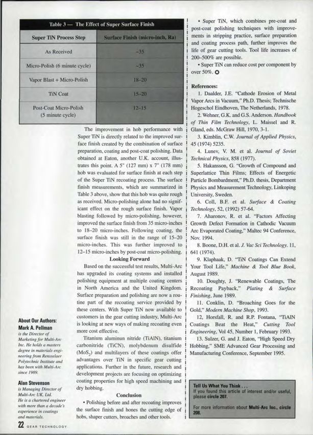
recoated            multiple 'times, as in the case of gear      In ]993 Multi-Arc initiated a development.
                                          cutting            tools. Hobs and shapers ace often          program to further improve recoated toelperfor-
                                          reground            and reeoatedas many as 20 times. This     mance. As mentioned above. the scope of mis
                                          can lead            to excessive roughening on the flanks     program included
                                          of hob teeth.                                                    • Study of tile effect of stripping pri.or to
                                                                          Reenating                     recoating,
                                             PVD TiN coaling has become widely used                        • 5rudy   of the effect of coating parameters on
                                          on metal enning tools since its introduction in               defect formation and growth,.
                                          the early 1980. Numerous technical papers                        .' Characterization of the effect of the polish-
                                          have been written confirming the advantages of                ing processes on tool surface finish and edge
                                          TiN coating and recoating (Refs. 9-W2). In the                condition.
                                          early 1980s, when recoating was a new concept,                   • Detennination of the performance of Super
                                          users of expensive TiN coated tools. such as                  TiN recoated bobs and shaper cutters ..
                                          hobs, broaches and shaper cutters, noticed that                                     Stripping
                                          tool performance decreased after sharpening ..                    Stripping prior to reeoating w.a investigated
                                          Sharpened tools cut fewer parts than the origi-               'to determine if it could reduce or eliminate peel-
                                          nal coated tool. Furthermore speeds and feeds                 back on the tooth flank on recoated bobs. Peel-
                                          often had to be reduced.                                      back occurs when the TiN coating delaminates
                                              Recoating wa ' developed. as a program to                 from the surface of the tool or between coating
                                          restore the performance of a sharpened too] to                 layers. With a recoated hob, as shown in Fig. W,
                                          that of the original coated tool. Recoating                    the adhesion between the successive Iayen of
                                          replaces the TiN coating on the cutting face of a              coaling can be compromised by contaminants
                                          tool each time it is harpened. The renewed coat-                ucb as glass bead particles, meta] build-up and
                                          ing allow tools to run at their optimum perfor-                Hake of old coating. Poor adhesion adjacent to
                                          mance levels. Recoating is a proven process that               oontaminants, in turn, provides an initiation site
                                          can cut tooling and production costs by as much                for coating delamination under the loads experi-
                                          as 20-40% (Ref. 10).                                           enced during cutting.
                                                                                                            The stripping technique studied involved
                                            Tool Life Without Stripping

     aOr-------------------------~~--------------~
     70
                                                                                                        immersing the coated hobs in a hydrogen per-
                                                                                                        oxide based solution at room temperature .. The
     SO                                                                                                  soluuon chemically reacts with titanium nitride,
     50                                                                                                 removing it and leaving a thin oxide on the hob.
     40
                                                                                                            The effect of coating build-up on too] per-
     30
                                                                                                        formance is Illustrated in. Fig. 2. Shaper cutters
     20
                                                                                                        were used to machine 4140 steel gears at a
      10
                                                                                                        manufacturer      of automotive trau missions.
       o
                  Original          1st                2nd             am         4th     5th           Afl.er each sharpening the cutters were liquid
                                                       Number 01 Uses                                   honed, cleaned and recoated with 2-3 m:icrons
                                              •        /I Pieces per Grind                              of TiN. Fig. 2 sllowsthe number of pieces pro-
                                                                                                        duced wiLh these cutters during six successive
Fill..2 - Number of pieces produced with II'\\toatcd TlN shaper cutters.
                                                                                                        uses of Ithe tool, which represents the average
                                                                                                        life span. Each point is the average of the
                                           Stripping         Prior 10 Recoaling

      ~r---------------~--------~----------~                                                            re ults produced by 10 tools. The results show
                                                                                                        Lhat the number of pieces machined decreased
                                                                                                        In less than balfthe original. coated 1001 perfor-
      3000
                                                                                                        mance after six recoatings. The drop in perfor-
      2500
                                                                                                        mance is attributed in part to change in tool
      2000                                                                                              geometry and clearance angles and in part to
      1500                                                                                              coating build-III'.
      1000                                                                                                  Most of the tool wear was isolated to one or
       500
                                                                                                        two teeth on the cutter. The majority of the 'teeth
                                                                                                        had onJy .005" (0.13 mm) of wear, but orne had
             o
                         Original                 lsi                    2nd                            peeled back on 'the tip. Once the coating wore
                                                         Number 01 Uses                                 llu:ough.to the substrate. the deterioration rapidly
                                                   •     /I Pieces per Grind                            p:rogres ed to a peel-back: stale. The firstteeth to
Fig. 3,-     Number of pieces,produced when. shaper cutter lis .stripped prior to recoating..           wear through the coating often progressed 'to'
18   BEAR'       TECHNOLOGY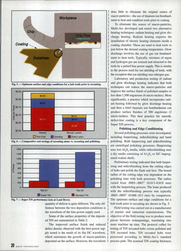
peel-hack before the machine cycle was finished,
resulting in wear as high as .095" (2.4 mm).
    When shaper cutters are stripped prior to
recoating with TIN, tbe number of pieces pro-
duced decreases, but much less dramatically.
    Data from Land Rover. which is illustrated in
Fig. 3, shows that an ASP 23 shape! cutter, when
stripped prior to every recoating, had a decrease
cfcnlyareuad      20%aiter sharpening and recoat-
ing 3 times. These cutters were 5" ([27 mm) in
diameter and l .5" (38 rom) .high operating at 35
sfm and. a .012" (0.3 mm)/stroke.
    The results show that the number of pieces
machined actually increased to. an average of
3,659 pieces following the first recoating when
compared to the original TiN coated hob. which
machined an average of 3,363 pieces. After sub-
sequent     harpening, stripping and recoaring
cycles, the life dropped into the range of 2,,700-
2,800 pieces/grind.
    Based on results like these, 'stripping of old
TiN coating prior to. recoating has become a stan-
dard Super TiN practice.
          Defect Fonnationand     Growth
    It is well known that hardoompound coatings
produced using cathodic arc deposition exhibit
higher roughness when compared w.ith sputtered
and E-beam deposited coatings. Many research-
ers have connected this problem to the droplet
emission during arcing on the target. The pro-
truding features from the coating surface are
often called "macros," "macro-particles"        or
"droplets." Based on Mujti-Arc's research, the
term "growth defect" would be more appropri-
ate. This conclusion is based on the observation
that macro-particles deposited during the condi-
                                                     Fig. 4 - SE if phetomlcrographs of TiN surface for the different bias. power supplies,
tioning phase of a coating cycle can either grow
as the cycle proceeds or be covered over as
coating material is deposited. Both growth and
macro-particle generation ure dependent on
process conditions.                                   Number of Evaporators
    Coating process conditions, in particular bias    Bias
voltage and bias voltage waveform, were studied.      Coating Cycle
to determine their effect on defect formation and     Number of Evaporators
growth. In order to determine the effect of wave-     Bias Voltage
form on defect growth and. propagation, several
                                                      Deposition Temperature
different power supplies were used to deposit TiN
                                                      ,-v,,,...,,,Thickness
coatings on high speed steel coupons i1\ a com-
mercial [ON BOND® PVD system, The coating
process protocol is listed in Table 1.
    Test coupons were fixtured ill a rotating fix-
ture facing the cathodes duri:ng the conditioning
and coating cycles. The typical SEM micrographs
                                                          Best                 3,01)1)               (1).000                    3
of the TiN coating deposited wi.th the best and
worst power supplies are shown in Fig. 4. It is          Worst                 7,000                 20,1)00                   20
obvious from these pictures that. the size and
                                                                                                           JANUARY/FEBRUARY         1997   19 1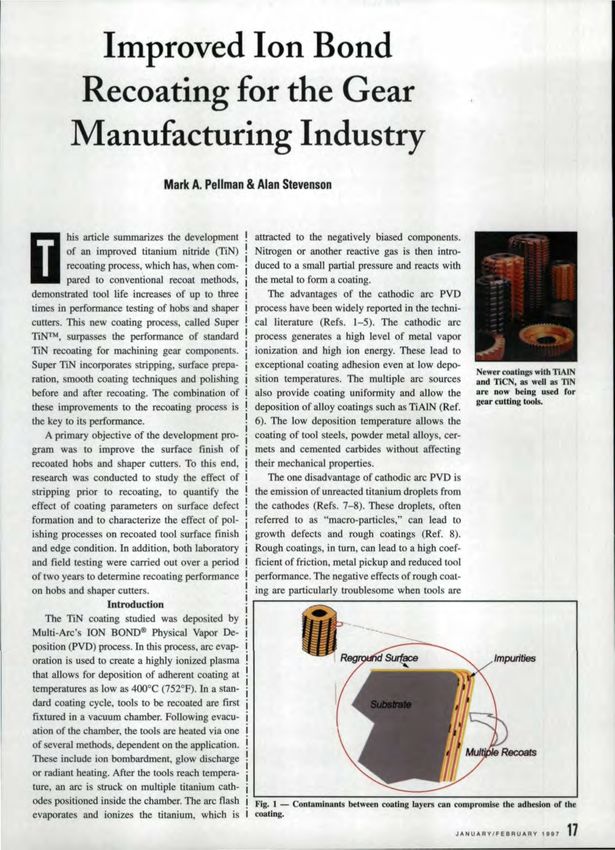
does little to eliminate the original ource of
macro-particles-the use of titanium ion bombard-
ment to heat and condition tools prior to coating.
To eliminate this source of macro-particles,
Multi-Arc developed and tested two alternative
heating techniques: radiant heating and glow dis-
charge beating. Radiant heating requires the
installation of electric heating elements inside a
coating chamber, These are used to heer tools to
just below the desired coating temperature. Glow
discharge involves the use of gas ion bombard-
ment to heat tools. Typically, mixtures of argon
and hydrogen gas are ionized and attracted to the
tools by a pulsed bias power supply. This is similar
to the process used for ion nitriding of tools, with
the exception that ion nitriding uses nitrogen gas.
Laboratory and production testing of radiarn
Fig. S - Optimum surface and edge conditions fora. hob tooth prior to recoatlng,
and glow discharge heating indicates that both
techniques can reduce the macro-particles and
improve the surface finish of polished samples to
less than 1,500 angstroms (6 micro-inches). More
$0.20 significantly, a practice which incorporates radi-
ant heating followed by glow discharge heating
§ $0.15 and then a brief titanium ion bombardment can
ii:
produce surface finishes of 5'00' angstroms (2
!
~ $0.10 rnicro-inches}.This best practice for smooth,
o defect-free coating is a key component of the
$0.05
Super TiN process.
Polishing and Edge Conditioning
$0.00
Recoal Recoa! +polish Several polishing processes were investigated,
Drool Cost • Grinding • Direct Labor including harperizing. mikrofinishing and hand
~ig. 6 - Comparative cost savings or recoating alone vs. recording and polish_ing. polishing. Both harperizing and mikrcfinishing
are centrifugal polishing processes. Harperizing
1600 uses wet AI20J media, while mikrofinishing uses
1400 a dry media consisting of A120] or SiC impreg-
1200 nated walnut shells.
1000
Preliminary testing indicated that both harper-
izing and mikrofinishing hone the cutting edges
~ 800
ii: of bobs andpolish the flank and face. The honed
"" 600
radius of the cutting edge was dependent on the
400 polishing time with both processes .. The radius
200 varied from .0005-,0007" (0.013-0.'018 mm)
0 with the harperizing process. The hone produced
Test 111 Test 112 with the mikrofinishmg process was typically
• Super TIN • Standard llN .0003-.0005" (0.008-,013 mm) by comparison.
Fig ..., - Supe.r TiN performance tests at Land Rover. The optimum surface and edge conditions for a
quantity of defects is quite different The only dif- hob tooth prior to recoating are shown in Fig. 5..
ference between the two deposition conditions is field testing was carried out at a manufacturer
the waveform of the bia power supply used. of marinea~d industrial transmissions. The
Some of the surface properties of the deposit- objective of the field testing was to produce more
ed TiN are summarized in Table 2. pieces between resharpenings, translating into
The improved surface finish and reduced more machine up time, The protocol called for
defect density observed with the best. power sup- testing afTiN recoated hobs versus poli hedand
ply tested is the result of its Hat DC waveform, TiN reccated hobs. TiN recoated hobs were
which minimizes the growth of macro-particles processed according to. Multi-Arc's standard
deposited on the surface. However, the waveform process path. The nominal TiN coating thickness
20 GEAR T!ECHNOLOG't'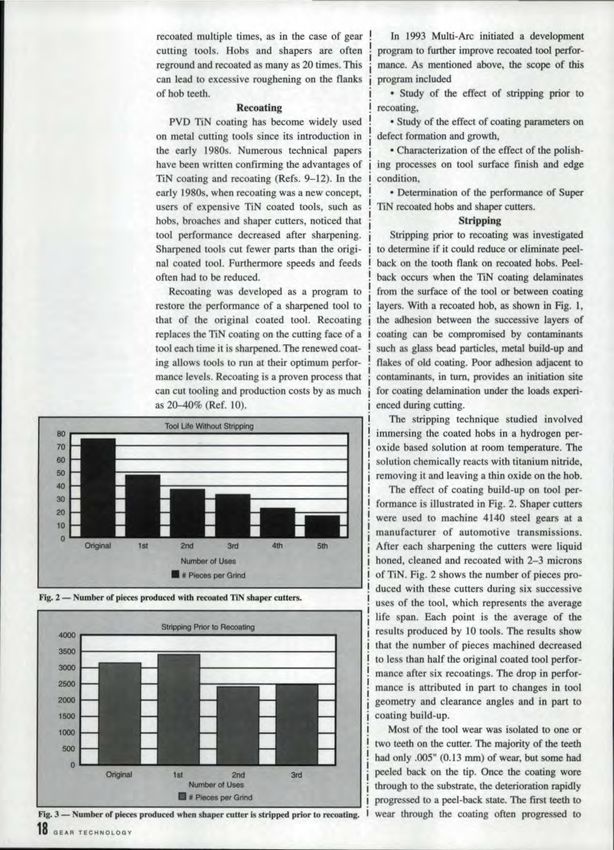
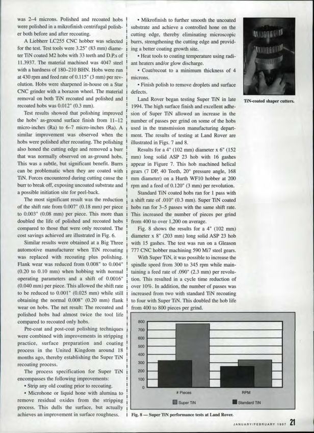
was 2-4 microns. Polished and reeoaied hobs              • Mikrofinisb to further smooth the uncoated
were polished in a mikrofmish centrifugal polish-     substrateand achieve a controlled hone on the
er both before and after recoating,                   cutting edge, thereby eliminating microscopic
    A Liebherr LC2-55 CNC bobber was selected         burrs, trengthening the cutting edge and provid-
for the test. Test tools were 3.25" (83 mm) diame-    ing a better coating growth site.
ter TLNcoated M2 hobs with 33 teeth and D,P:s of         o Heat tools to coating temperature using radi-

11.3937. The material machined was 4047 steel         ant hearers and/or glow discharge.
with a hardaes of 180-2W BHN. Hobs were run               • Coat/recoat to a minimum thicknes of 4
at 430 rpm and feed rate of 0.1] 5" (3 mm) per rev-   microns.
elution. Bobs were sharpened in-house on a Star           • Fini hpolish to remove droplet and surface
CNC grinder witb at borazon wheel. The material       defects.
removal on bothTlN reeoated and polished and              Land Rover begaatesting Super TiN in late
recoated hob was 0,01.2" (0.3 ID3Il),                 1994..The high surface finish and excellent adhe-
    Test results showed that polishing improved       sion of Super TiN allowed an increase in the
the hobs' as-ground surface finish from U-12          number of passes per grind on some of the hobs
micro-inches (Ra) to 6-7 micro-inches (Ra), A         used in the transmission manufacturing depart-
similar improvement was ob erved when the             ment. The results of testing at Land Rover are
hobs were polished after recoating. The polishing     illustrated in Figs. 7 and 8.
also honed the cutting edge and removed a burr            Results for a 4" (102 rnmjdiameter x 6" (152
that was normally observed on as-ground hobs,         mm) tong solid ASP 23 hob with 16 gashes
This was a subtle, but significant benefit, Burrs,    appear in Figure 7. This hob machined helical
can be problematic when they are coated with          gears (7 DP; 40 Teeth. 200 pressure angle, [68
TIN. Forces encountered during cutting cause the      mm diameter) on a Hurth WFlO hobber a:t 200
bUIT to break off, exposing uncoated sub trate and    rpm and a feed of 0,]20" (3 mm) per revolution.
a possible initiation site for peel-back,                 Standard TiN coated hobs ran for 1 pa s with
    The most significant result was the reduction     a hift rate of ,OW" (0,3 mm). Super TiN coated
of the shift rate from 0,007" (0,18 mmjper piece      hobs ran for 3-5 passes with the same hift rate.
to 01.003" (0.08 mm)per piece. This more than         This increased the number of pieces per grind
doubled the life of polished and recoared hobs        from 400 to over 1,200 on average.
compared to those that were only recoated, The            Fig .. 8 shows the results for a 4" (102 mm)
co t savings achieved are iI1ustrated in Fig ..6.     diameter x 8" (203 nun) long solid ASP 23 hob
    Similar results were obtained at a Big Three      with 15 gashes. The test was run on a Gleason
automotive manufacturer when TIN recoating            777 CNC bobber machining 590 Mi7 steel gears.
wasrep.laced      with recoating plus polishing,          With Super TiN. it was possible to increase the
Flank wear was reduced from 0.008" to 0.004"          spindle speed from 300 to 345 rpm while main-
(0.201 to 0.10 mm) when hobbing with norma]           taining a. feed rate of .090" (2.3 mm) per revolu-
operating parameters and a shift of 0,00'16"          tion. This resuked in a cycle time reduction of
(0.040' mm) per piece. This allowed [he shift rate    over 1O~ .Jn addition. the number of passes was
to be reduced to 0.001" (0.025 mm) while still        increased from two with standard TiN recoating
obtaining the normal 0.008" (0.20 mm) flank           to four with Super TiN, This doubled the hob life
wear on hobs.The net result: The recoated and         from 400 to 800 pieces per grind.
poli hed hob had almost twice the tool life
compared to recoated cnly hobs,
    Pre-coat and post-coat poli bing techniques
                                                          8OOr--------- ..............
                                                          700 .11-----
                                                                           ---------...,
were combined with improvements in stripping             6001-----
practice. surface preparation          and coating       5001-----
process in the United Kingdom around 18
                                                         4OOt-----
month ago, thereby establishing the Super TiN
                                                         300
recoating process.
    The process specification for Super TiN              200

encompasses tbe following improvements:                   100
    • Strip any otd coating prior to recoating.             o
    • Microhone or liquid hone with alumina to                                                                           RPM

remove residual oxides frorn the stripping                                  •   Super TiN                       •      Standard TiN
process. This duns the surface, but actually
achieves all improvement ill surface roughness.       Fig. 8 -   Super TiN perfonnan~       lesl.'lat L!U!dRover.

                                                                                                                    J,o,NUARY/Fea'RUA:RY   1~97   21'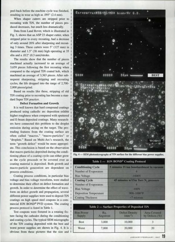
• Super TiN, which combines pre-coat and
                                                                                    post-coat polishing techniques with jmprove-
        Super TiN Process Step                                                      merits in stripping practice, surface preparation
                                                                                    and coating process path, further improves the
                As Received                                                         life of gear cutting tools. Tool life increases of
                                                                                    200-500% are possible.
     Micro-Polish (6 minute cycle)                                                      • Super TiN can reduce cost per component by
                                                                                    over 50%.0
      Vapor Blast + Micro-Polish
                                                                                     References:
                   TiN Coat                                                             1. Daalder, J.E. "Cathode Erosion of Metal
                                                                                    Vapor Arcs in Vacuum," Ph.D. Thesis; 'Ieehnische
         Post-Coat Micro-Polish                                                     Hogeschol Eindhoven, The Netherlands, ]978.
            (5 minute cycle)                                                           2. Wehner, G.K. and U.S. Anderson . .Handbook
                                                                                    of Thin Film Technology, L. Maissel and R.
                                   The improvement in bob performance with          Oland, eds ..McGraw Hill, 1.970,3-]'
                               Super Ti is directly related to the improved sur-       3. Kirnblin, c.w. Journal o.f Applied Physics,
                               face finish created by the combination of surface    45 (]974) 5235.
                               preparation, coating and post-coat polishing. Data      4. Lunev, V. M. etaI. Journal of Soviet
                               obtained at Eaton,another U.K. account, ill us-      Technical Physics, 858 (1977).
                               trates this point. A 5" (]27 rum) x 7" (n8 IDJlIl)      5. Hakansson, G. "Growth of Compound and
                               hob was evaluated for surface finish at each step    Superlattice Thin Films; Effects of Energetic
                               of the Super TiN recoating process. The surface      Particle Bombardment," Ph.D. thesis, Department
                               finish measurements, which are summarized in         Physicsand Measurement Technology, Liakoping
                               Table 3 above, show that this hob was quite rough    University, Sweden.
                               as received, Micro-polishing alone had no signif-       6. con, B.E et aI. Surface & Coating
                               icant effect on the rough surface finish. Vapor      Technology, 52, (1992) 57·64.
                               blasting followed by micro-polishing, however,          7.. Aharonov, R. et al, "Factors Affecting
                               improved the surface finish from 35 micro-inches     Orowth Defect Formation in Cathodic Vacuum
                               to 18-20 micro-inches. Following coating, the        Arc Evaporated Coating," Maltec 94 Conference,
                               surface finish was still in the range of 15-20       Nov. 1994.
                               micro-inches. This was further improved to              8. Boone, D.H.et aI. J. Vac Sci Technology. u,
                               12-]5 micro-inches by post- coat micro-polishing,    64] (l974).
                                               LookJng Forward                         9. KJaphaalt. D. "TiN Coanngs Can Extend
                                   Based on the uccessful test results, Multi-Arc   Your Tool Life," Machine & Tool Blue Book,
                              has upgraded its coating systems and installed        August 1989.
                              polishing equipment at multiple coating centers          10. Doughty. 1. "Renewable Coatings. The
                              in North America and the United Kingdom.              Recoating     Payback."    Plating & Surface
                              Surface preparation and polishing are .now a rou-     Finishing. June 1989.
                              tine part of the recoating service provided by           J L Conklin, D. "Broaching Goes for the
                              these centers. With Super TiN now available to        Gold," Modem Machine Shop, 1993.
                              customers in the gear cutting industry, Mul.ti·Arc       12, Horsfall, R. and R.P, Fontana, ''TiAlN
About lOur Authors:
                              is looking at new ways of making recoating even       Coatings Beat the Heat," CUlling             Tool
,Marie:A~ Penman
                              more cost effective.                                  Engineering, Vo145, Number I, February 1993.
is Ihe Director of
Marketing for Multi-Arc           Titanium alnminun nitride (TiAlN), titanium          n. Sulzer, G. and 1. Eaton. "High Speed Dry
Inc. He holds a masters       carbonitride (TiCN), molybdenum disulfide             Hobbiag," SME Advanced Gear Processing and
degree ill materials engi-
                              (MoS2)and multi layers of these coatings offer        Manufacturing Conference, September 1995.
neering from Rensselaer
Polytechnic Institute and     advantages over TiN in specific gear cutting
has been with Multi-Arc       applications. Further in the future, research and
since 1989.                   development projects are focusing on optimizing
AlanlStevenson                coating properties for high speed machining and
                              dry bobbing,                                           rell Us WINd Y_ TIll •...
is Ma7l(lging Director of
                                                                                     If you found this article of interest and/or usaful,
Multi-Arc UK. ud.                                 Condusi.on                         please cIrGIt .,

                                                                                     -
He is a. chartered engineer
                                  • Polishing before and after recoating improves
with more than a decade's
                              the surface finish and hones the cutting edge of       For more information about MIdIi-Are ..... afnIII
experience ill' coatings
and materials.                hobs, shaper cutters. broaches and other tools.
22   G~"'R   TECHIo!OlOG'(
You can also read