Vertical Shaft Support Improvement Studies by Strata Grouting at Aquifer Zone

Page created by Theresa Gray
 
CONTINUE READING
Vertical Shaft Support Improvement Studies by Strata Grouting at Aquifer Zone
Hindawi
Advances in Civil Engineering
Volume 2018, Article ID 5365987, 10 pages
https://doi.org/10.1155/2018/5365987

Research Article
Vertical Shaft Support Improvement Studies by Strata
Grouting at Aquifer Zone

          Qing Yu ,1,2 Kexin Yin,3 Jinrong Ma ,4 and Hideki Shimada                                     5

          1
            School of Resources and Geosciences, China University of Mining and Technology, Xuzhou, China
          2
            Jiangsu Collaborative Innovation Center for Building Energy Saving and Construction Technology, Xuzhou, China
          3
            Research Institute in Civil and Mechanical Engineering (GeM), UMR CNRS 6183, Ecole Centrale de Nantes, Nantes, France
          4
            State Key Laboratory for GeoMechanics and Deep Underground Engineering, China University of Mining and Technology,
            Xuzhou, China
          5
            Department of Earth Resources Engineering, Faculty of Engineering, Kyushu University, Fukuoka, Japan

          Correspondence should be addressed to Jinrong Ma; jrma@cumt.edu.cn

          Received 4 August 2017; Revised 23 February 2018; Accepted 18 March 2018; Published 25 June 2018

          Academic Editor: Li Li

          Copyright © 2018 Qing Yu et al. This is an open access article distributed under the Creative Commons Attribution License, which
          permits unrestricted use, distribution, and reproduction in any medium, provided the original work is properly cited.
          The shaft lining failure which occurs in deep alluvium is a sudden coal mine hazard. The strata grouting is one of the treatment
          methods for the shaft lining failure. To investigate the impact of grout injection pressure on the shaft lining, the field measurement
          and the numerical analysis of the shaft lining stress variation during the grouting were conducted. To improve the strata grouting,
          the underground continuous impervious curtain (UCIC) is proposed as a new method by using the chain conveyor cutter
          technique without the impact on the shaft lining. The effects of the new method were also analyzed by means of the numerical
          methods. The results show that the strata grouting in the deep alluvium needs a high injection pressure, and in the horizontal
          direction, the shaft lining sustains the repeat tensile and compressive force during the grouting process. The negative influence of
          strata grouting on the stability of the shaft lining is obvious and serious. The UCIC built around the shaft lining can restrain the
          stress concentration induced by the aquifer drawdown. The triangular UCIC has a similar effect as that of the vertical one, and the
          small angle is better for preventing the shaft lining failure.

1. Introduction                                                          deformation and failure even though under the condition
                                                                         of enough shaft pillars left around the shaft [11]. The
Coal mining operation caused many problems such as                       settlements of the mining fields which happened near the
ground settlement, shaft lining instability, surrounding                 shaft lining failure were about 0.2–0.5 m, and it increased
strata deformation, aquifer leakage, rock burst, and water               with increasing the distance from the shaft. When shaft
inrush [1–9]. Among them, serious shaft lining failures have             lining failure occurs, the inner shaft lining delaminates and
often occurred in the eastern part of China, such as Datun,              spalls, longitudinal steel bows inward, transverse cracks
Xuzhou, Huaibei, Huainan, Yanzhou, and Yongxia, since                    form and intersect in the horizontal direction along circle,
1987 [10]. The shaft lining failure which occurs in deep                 seepage occurs or even sand gushes, and mostly seriously,
alluvium is a sudden coal mine hazard. The number of                     concrete blocks fall out and may damage the equipments in
failure shafts and their large ranges have never been seen               the shaft. In addition, the shaft bends up; cage guides,
before in Chinese mining history and are also rare in the                drainpipes, and pressure ventilation pipes are in longi-
world. During the mining process, the failure of the shaft               tudinal bending; and in serious cases, the cage is stuck due
lining is a serious hazard to mining operation and mine                  to torsional deformation [12]. Thus, the shaft lining failure
safety. The main feature is that the part of the shaft lining            has a serious impact on the operation of the coal mine and
which passes through the aquifer has the most serious                    the safety [13].
Vertical Shaft Support Improvement Studies by Strata Grouting at Aquifer Zone
2                                                                                                Advances in Civil Engineering

     After many years’ researches, the mechanism of the shaft     casing into the aquifer near the rupture location. The
lining failures has become clear. The vertical additional force   borehole must reach the predesigned locations in the bottom
theory is described as follows. There is a thick bottom soil      aquifer, and then the grout is injected into the soil to fill the
aquifer under the steady impermeable layer, and the aquifer       soil pores, compact and compress the soil, and cement soil
is in direct contact with the weathered rock which is in the      particles. Up to now, there are mainly two grouting methods
top of bedrock in all broken shafts. The special mining           for strata reinforcement: one is grouting behind the segment,
activities and the artificial drainage cause the water levels      and the other is grouting from the surface (Figure 1) [30].
drop in the soil aquifer. According to the drop of water level        The strata grouting in deep alluvium needs a high in-
in the aquifer, the stratum of aquifer deforms and then the       jection pressure. In the aquifer, the water pressure is high
effective stress increases in the aquifer. This can lead to        due to the confined aquifer, and the injection pressure needs
consolidation of the soil strata and subsidence of the surface.   to be higher than the water pressure. So, the risk of shaft
During the process of strata settlement, the soil layer im-       lining failure is raised due to the influence of the injection
poses a vertical additional force on the outer surface of the     pressure on the shaft lining. Though the strata grouting has
shaft. While the vertical stress increases gradually to its       the functions to restrain and release the additional vertical
limitation, the shaft lining cannot resist the force and then     stress, it may cause the damage to the shaft lining inversely.
fails. The failure mostly occurred near the interface between     In some cases, due to the improper control of the injection
aquifer and bedrock, sometimes in the alluvium a few meters       pressure and the uncertain distribution of the fracture, the
above the bedrock [14–17]. Many results of shaft lining           leakage of grouting material or even more the failure would
destructive tests and the data of in situ experiment con-         occur in the shaft lining (Figure 2). Therefore, the impact of
ducted in mining areas of Huaibei, Xuzhou, and so on,             grout injection pressure on the shaft lining needs to be
confirmed the existence of vertical additional force and its       investigated.
influence on the shaft lining failures [18–20]. Many re-
searchers did a lot of work on the laboratory test and field
test to verify this theory and made a great achievement.          2.1. Field Measurements. Yang et al. conducted the field
     As these subsidence might be related to the bottom aquifer   measurements in the main shaft of Baodian coal mine in
drainage and consolidation settlement, the most important         order to obtain the distribution of strains of the shaft lining
and difficult task is how to prevent the shaft lining from the      during the grouting process in 2000 [27]. The net diameter of
effect of the aquifer drawdown in deep alluvium. The study on      the main shaft in Baodian mine was 6.5 m, and the thickness
the mechanism of shaft lining failure and its treatment           of the shaft lining was 1.0 m. The thickness of alluvium was
practices were started in Zhangshuanglou coal mine and            148.69 m, and it contained 3 aquifers. The bottom aquifer
Kongzhuang coal mine [20, 21]. Since 1995, in Yanzhou area,       was important to the mine, and the water level was affected
the strata grouting has been applied to the treatment for the     by mining. The failure location was at −136 to −144 m depth,
shaft lining failure [22]. Cui and his research group conducted   and the grouting range was −93.5 to −149.0 m depth. The
the treatment in Zhangshuanglou coal mine and applied the         target layer of grouting was mainly the sand layer and the
strata grouting method to repair the shaft lining failure in      occasional clay layer. The initial grout injection pressure was
Baodian coal mine [23]. The strata grouting is a positive re-     2–4 MPa, and the maximum pressure and the end pressure
inforcement technique to control the shaft lining failure         were less than 6 MPa. The sites of grouting holes Z1–Z10 and
[24–26]. However, the negative influence of the strata grouting    the layout of concrete strain meters 1#–8# in the inner shaft
on the shaft lining is obvious and large [27]. Moreover, due to   lining are shown in Figure 3. The strain meters were set at
the grouting process is in the soil layer, the effect of the in-   four measuring levels, the first level was at −92.5 m depth; the
jection pressure on the shaft lining depends on the actual        second one was −116.5 m depth; the third one was −129.5 m
formation conditions and the treatment effect cannot be            depth; and the fourth one was −148.5 m depth.
guaranteed [28, 29]. It is necessary to establish a new method        Figure 4 shows the horizontal circumferential strain
for the failure treatment which has the effect of the strata       curves of the measuring points during alternately grouting in
grouting and not the negative influence.                           −129 to −131 m depths (Z5 and Z7). From the curves ob-
     In this paper, grouting pressure impaction on the shaft      tained, when grouting was conducted in Z5, the strain meter
lining is analyzed by means of field investigations and            4# had the relative tensile strain at the third measuring level,
numerical methods. Then, the underground continuous               and the other side strain meter 6# at the third measuring level
impervious curtain (UCIC) is proposed as an improvement           had the relative compressive strain. On the other hand, when
for the strata grouting, and the effects of the UCIC are           grouting was conducted in Z7, the relative tensile strain was
analyzed by means of the numerical methods. After that, the       measured in strain meter 6# and relative compressive strain
different angles which the UCIC is constructed and the             was measured in strain meter 4#.
appropriate angle for the UCIC construction are discussed.            Two tensile zones and two compressive zones were
                                                                  observed in the inner margin. Two tensile zones were
2. Analysis of Impaction of Grouting                              generated at neighborhood and remote area of the grouting
   Pressure on Shaft Lining                                       hole. The central angle of the compression zone or tensile
                                                                  zone was about 90°. From the results, it can be concluded
Strata grouting for shaft lining treatment requires drilling      that the shaft lining would bear the overload nonuniform
into the strata around the shaft and grouting though the          horizontal stress by the improper selecting of grouting
Vertical Shaft Support Improvement Studies by Strata Grouting at Aquifer Zone
Advances in Civil Engineering                                                                                                                                                                               3

                                                                          Shaft lining

                                                                                                                                                Shaft lining
                                                             Strata

                                                                                               Grouting
                                                                                                          Strata
                                                                                                                                                                 Grouting

                                                                                 (a)                                                                     (b)

                           Figure 1: Sketch of the grouting method. (a) Grouting behind segment. (b) Grouting from surface.

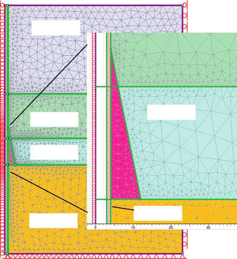
                                                             Figure 2: Leakage and failure during the grouting.

                                                  9.0 m
                                                                                                             Circumferential strain (×10–6)

                                   m                                                                                                          140
                             7.5
                                             Z3
                                                               Z4                                                                              90
                     m
                                                                               10.

                             Z2
               9.0
                                                                                  5m

                                        Shaft lining                                                                                           40

                     Z1                                                                  Z5
                                                                                                                                              –10
                               1#, 2#               3#, 4#
                                                                                                   N                                          –60
  10.5 m

                                                              Ø30.0 m                                                                               90              92           94         96   98   100
                                                                                          10.5 m

                                                                                                                                                                                   Time (d)
                             7#, 8#                5#, 6#                                                                                                      4# strain meter
                     Z10                                              Z6                                                                                       6# strain meter
                             Strain meters
                                                             Grouting holes                               Figure 4: Circumferential strain curves during alternately grouting
           m

                                                                                                          at the third measuring level [27].
           8.5

                                                                           9.0
                     Z9                            Z7
                                                                      m
                                        Z8
                           7.5 m              8.5 m                                                       positions or grouting orders. However, as the field mea-
                                                                                                          surements of the strain change during the grouting process,
Figure 3: Sites of grouting holes and layout of concrete strain                                           it is necessary to study about the stability of the shaft lining
meters [27].                                                                                              during the grouting process in detail.
Vertical Shaft Support Improvement Studies by Strata Grouting at Aquifer Zone
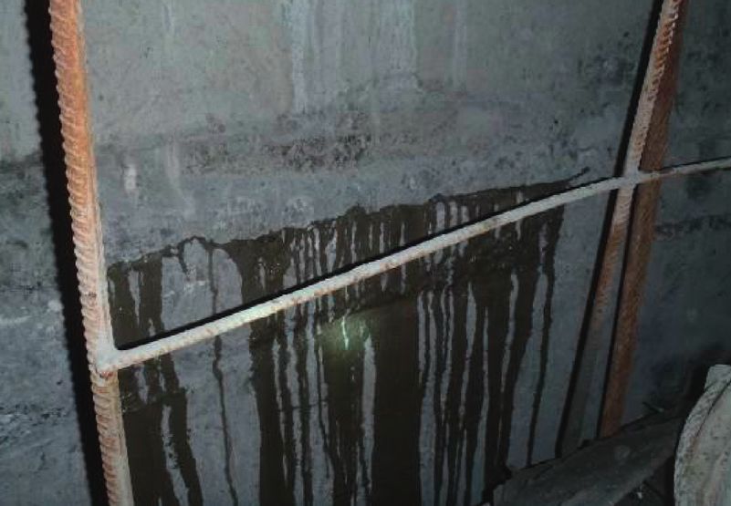
4                                                                                                                                                  Advances in Civil Engineering

     10                                                                 10                                                            10
                                                                                                                                                              Grouting holes

                                                                              5m
     7.5                                                               7.5                                                            7.5
                                                 Grouting hole                                                  Grouting holes
      5                                                                  5                                                             5
     2.5                                 D                             2.5                                D                           2.5                                 D

                                                                              10 m
      0                      A                  C                        0                        A              C                     0                      A                  C
    –2.5                                                              –2.5                                                           –2.5
                                          B                                                                 B                                                             B
     –5                                                                 –5                                                            –5
    –7.5                                10 m             5m           –7.5                               10 m             5m         –7.5         5m                     10 m             5m
           –10
                 –7.5
                        –5
                                 –2.5
                                        0
                                               2.5
                                                     5
                                                         7.5
                                                               10

                                                                                –10
                                                                                      –7.5
                                                                                             –5
                                                                                                  –2.5
                                                                                                         0
                                                                                                                2.5
                                                                                                                      5
                                                                                                                          7.5
                                                                                                                                10

                                                                                                                                            –10
                                                                                                                                                  –7.5
                                                                                                                                                         –5
                                                                                                                                                                  –2.5
                                                                                                                                                                         0
                                                                                                                                                                                2.5
                                                                                                                                                                                      5
                                                                                                                                                                                          7.5
                                                                                                                                                                                                10
                                    (a)                                                               (b)                                                           (c)

Figure 5: Geometry model of grouting around the shaft lining. (a) Single hole grouting. (b) Double holes grouting (90°). (c) Double holes
grouting (180°).

                             Table 1: The mechanical parameters of the aquifer, the shaft lining and the interface [12, 27].
Element type                                                   Shaft lining                              Aquifer                                     Interface
Elastic modulus (MPa)                                            20,000                                    42                        Normal modulus (MPa)                                            100
Poisson’s ratio                                                   0.15                                     0.3                        Shear modulus (MPa)                                            100
Interior friction angle                                            35°                                    20°                                 20°
Cohesion (MPa)                                                     35                                     0.04                                0.03

2.2. Simulation of Grouting Pressure Impaction. Finite ele-                                                           points to the grouting holes (points C and D) and the
ment software is used to simulate the impact of grouting                                                              opposite areas A and B. The stress in other area is
pressure during the grouting process. Phase2 7.0 is a 2D elastic-                                                     higher than these points and the peak stress appears
plastic finite element analysis program for underground or                                                            in the area of AD (4.6 MPa), BC (4.6 MPa), and CD
surface excavations in rock or soil [31]. Three geometry models                                                       (2.7 MPa). As the grouting pressure increases, the
(Figure 5) are established, and the initial grouting pressures are                                                    stresses at points C and D and area AB increase
set at 2 MPa, 4 MPa, 6 MPa, and 8 MPa. The mechanical                                                                 slightly due to the tensile effect, and the stresses in
properties of the aquifer, the shaft lining, and the interface                                                        area AD, BC, and CD are increased due to the
used in these analyses are shown in Table 1 [12, 27]. As the                                                          compression effect.
stress accumulates around the inner lining, the values of the                                                     (3) Double holes grouting (180°) (Figure 6(c)): The
deviatoric stress (a condition in which the stress components                                                         deviatoric stress is small in the shaft lining at nearest
operating at a point in a body are not the same in every                                                              points to the grouting holes (points A and C), and in
direction. Also known as differential stress) along the cir-                                                          other areas, the stresses are higher than the two
cumference of the inner lining are used to evaluate the in-                                                           points. It can be seen that as the grouting pressure
fluence of grouting pressures on the shaft lining as shown in                                                         increases, the stresses at points A and C are increased
Figure 6.                                                                                                             due to the tension effect, and the stresses in other
    From this analysis, some important results are obtained                                                           areas are increased due to the compression effect.
as follows:
                                                                                                                The minimum principal stresses in the shaft lining in the
     (1) Single hole grouting (Figure 6(a)): The deviatoric stress                                          three models are shown in Figure 7. From the results ob-
         is small in the shaft lining at the nearest point to the                                           tained, tensile stress acts in the minimum principal stress
         injected hole (at point C) and the opposite position (at                                           plane during the grouting process. And as the grouting
         point A). The stress in other areas is higher than these                                           pressure is increased, the tensile stress increased in the zone
         two points, and the peak stress is observed at points B                                            for which the deviatoric stress is low. Although the devia-
         (5.8 MPa) and D (4.7 MPa) near the 90° central angle to                                            toric stress is low, it is still not safe for the shaft lining.
         the lowest stress area. As the grouting injection pressure                                         Comparing the results of the three grouting positions in
         is increased, the stresses in zones A and C are decreased                                          Figure 5, the minimum deviatoric stress is appeared in the
         due to the tension effect, and the ones in zones B and C                                           zone near the injected hole; the peak stress in the second
         are increased due to the compression effect. The                                                   grouting position is less than that for two other grouting
         maximum peak value between points B and C is                                                       positions; when the injected holes are distributed in a row,
         5.4 MPa, and this is a danger part of the shaft lining.                                            much more peak stresses appear, and these have a large
     (2) Double holes grouting (90°) (Figure 6(b)): The                                                     impact on the shaft lining. For example, in Figure 7(c), the
         deviatoric stress is small in the shaft lining at nearest                                          points A and C of the shaft lining are easy to fail.
Vertical Shaft Support Improvement Studies by Strata Grouting at Aquifer Zone
Advances in Civil Engineering                                                                                                                                                                                   5

                                 6                                                                                                                  6

                                 5                                                                                                                  5
       Deviatoric stress (MPa)

                                                                                                                          Deviatoric stress (MPa)
                                 4                                                                                                                  4

                                 3                                                                                                                  3

                                 2                                                                                                                  2

                                 1                                                                                                                  1

                                 0                                                                                                                  0
                                     A           B         C                                        D              A                                    A                B         C              D        A
                                     0       5         10        15                                     20         25                                   0            5         10        15           20   25
                                                     Circumstance (m)                                                                                                        Circumstance (m)

                                         2 MPa                                              6 MPa                                                               2 MPa                     6 MPa
                                         4 MPa                                              8 MPa                                                               4 MPa                     8 MPa
                                                        (a)                                                                                                                       (b)
                                                                                    6

                                                                                    5
                                                          Deviatoric stress (MPa)

                                                                                    4

                                                                                    3

                                                                                    2

                                                                                    1

                                                                                    0
                                                                                        A                   B         C                                         D            A
                                                                                        0               5         10        15                                      20       25
                                                                                                                Circumstance (m)

                                                                                               2 MPa                                                    6 MPa
                                                                                               4 MPa                                                    8 MPa
                                                                                                                    (c)

Figure 6: Deviatoric stress changes along the circumference of inner lining. (a) Single hole grouting. (b) Double holes grouting (90°).
(c) Double holes grouting (180°).

     The strata grouting in the deep alluvium needs a high                                                                 failure, a new method for shaft lining failure treatment
injection pressure, and in the horizontal direction, the shaft                                                             which constructs the underground continuous impervious
lining sustains the repeat tensile and compressive force                                                                   curtain (UCIC) is proposed. This new method is supposed to
during the grouting process. And the grouting pressure is                                                                  have an effect to reinforce the strata around the shaft such as
difficult to be controlled due to the complex geological con-                                                              the strata grouting, but the control of grouting range is easy;
ditions. The negative influence of the strata grouting on the                                                              furthermore, the impact on shaft lining is lower than that of
stability of the shaft lining is obvious and serious. The risk of                                                          the grouting method. By using the chain conveyor cutter
shaft lining failure due to the grouting method is high.                                                                   technique [32], the UCIC can be constructed uniformly in
Therefore, the grouting method is not a conclusive solution for                                                            the strata as an underground wall that has the antiseepage
shaft lining failure.                                                                                                      capacity. This method for shaft lining failure has been de-
                                                                                                                           veloped based on the mechanism of shaft lining failure and
3. Measures for Improvements of                                                                                            from the existing treatment methods such as strata grouting
   Strata Grouting                                                                                                         and the previous shaft sinking method which is the concrete
                                                                                                                           curtain method [33]. The concrete curtain method is to drill
3.1. Introduction of UCIC. Based on the results of an analysis                                                             holes from the ground surface around the shaft zone and
of other methods and the mechanism of the shaft lining                                                                     injects the concrete grout in order to form a cylinder
Vertical Shaft Support Improvement Studies by Strata Grouting at Aquifer Zone
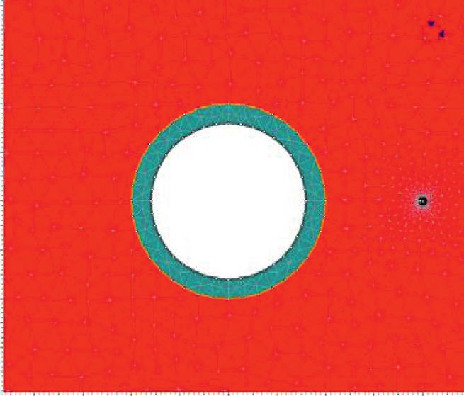
6                                                                                                                                                                                                                            Advances in Civil Engineering

                                      0.8                                                                                                                                             0.6
                                      0.6                                                                                                                                             0.4
    Minimum principal stress (MPa)

                                                                                                                                                    Minimum principal stress (MPa)
                                      0.4
                                                                                                                                                                                      0.2
                                      0.2
                                       0                                                                                                                                               0
                                            0        5             10                                       15                     20        25                                             0         5            10              15       20       25
                                     –0.2                                                                                                                                            –0.2
                                     –0.4
                                                                                                                                                                                     –0.4
                                     –0.6
                                                                                                                                                                                     –0.6
                                     –0.8
                                      –1                                                                                                                                             –0.8
                                     –1.2                         Circumstance (m)                                                                                                    –1                          Circumstance (m)
                                                Before grouting                                             2 MPa                                                                               Before grouting                     2 MPa
                                                4 MPa                                                       6 MPa                                                                               4 MPa                               6 MPa
                                                8 MPa                                                                                                                                           8 MPa
                                                                     (a)                                                                                                                                               (b)
                                                                                                          0.8
                                                                        Minimum principal stress (MPa)

                                                                                                          0.3

                                                                                                                0                  5          10                                        15          20            25
                                                                                                         –0.2

                                                                                                         –0.7

                                                                                                         –1.2                                Circumstance (m)
                                                                                                                    Before grouting                                                     2 MPa
                                                                                                                    4 MPa                                                               6 MPa
                                                                                                                    8 MPa
                                                                                                                                                  (c)

Figure 7: Minimum principal stress changes along inner lining. (a) Single hole grouting. (b) Double holes grouting (90°). (c) Double holes
grouting (180°).

                                                                                                                              Ground
                                                                                                                    Shaft lining

                                                                                                                                                                                                                             Shaft lining

                                                                                                                                                                                                                                   UCIC
                                                                                                                                    Overburden

                                                              UCIC

                                                                                                                                   Aquifer

                                                                                                                            Bedrock

                                                                                                         Figure 8: Sketch of the UCIC for shaft lining treatment.
Vertical Shaft Support Improvement Studies by Strata Grouting at Aquifer Zone
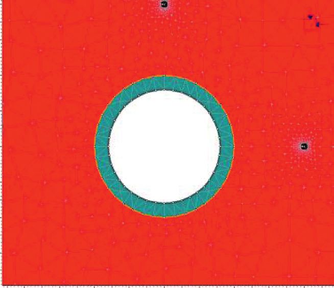
Advances in Civil Engineering                                                                                                          7

                                                                    model used to imitate the geological condition is shown in
                                                                    Figure 10, and the mechanical properties used in the analysis
                                                                    are shown in Table 2. The parameters in this model are based
                                                                    on the geological data and the shaft construction data of
                                                     Crane wire     Baodian coal mine where shaft lining failures occurred
                                                                    [12, 22, 23, 27]. The UCIC is assumed to be applied to this coal
                                                                    mine. In this simulation, the space between UCIC and shaft
                                                                    lining is left in order to eliminate the influence of the in-
                                                                    teraction between UCIC and shaft lining, and the appropriate
                                                                    angle for the UCIC construction is also discussed. The initial
                                                                    water level in the bottom aquifer is −25 m, and after the water
                     Shaft lining

        Strata                                                      level dropping, it changes to −45 m.
                                                  Rack and
                                                                         The numerical simulation is divided into two steps: The
                                                   pinion           first step is to balance the stresses that act between the strata
                                                                    and the shaft lining under the initial stress, and the initial stress
                                                                    is generated by the gravity and the lateral pressure of strata.
                                                                    The second step is to drop the water level, and then the aquifer
                                                                    was consolidated interacting with the shaft lining by the ad-
                                                                    ditional stress.
                                                                         The tilt directions of apply patterns are shown in Table 3.
                                    0.8 ~ 1.0 m                     The influence of the angles of the UCIC is investigated in the
                                                                    analysis. The UCIC is constructed in the aquifer layer around
                                                                    the shaft lining. After the drop of water level, the effect of the
                                                                    UCIC on the shaft lining is discussed. As the stress accu-
                                                                    mulated around the inner lining, the values of the maximum
       Figure 9: Field application schematic of the CCC.
                                                                    principle stress in the shaft lining are used to evaluate the
                                                                    effect of the UCIC on the shaft lining.
                                                                         The results of the effect of the treatment are shown in
concrete curtain around the shaft for supporting and wa-            Figure 10. Figure 11 shows the maximum principal stress
terproofing. From 1974 to 1980, this method was applied to          changes in the inner surface of the shaft lining as the UCIC
about twenty shafts. However, the sinking depth of this             was applied at different angles. It can be seen that a peak
method is less than 80 m, and it cannot be applied to the           stress happens in the lower part of the bottom aquifer after
thicker alluvium shaft sinking.                                     the drop of water level. So, most of the shaft lining failures
    The UCIC is designed outside of the shaft lining in a certain   occur near this boundary. From those results, under the
area, adopting the vertical cutting and mixing technique, chain     initial stress state, the maximum principle stress in the inner
conveyor cutter (CCC), and mixing cement grout with soil or         surface of the shaft lining increases with increasing the
concrete to be a wall, and the construction technique needs to      depth, and its magnitude changes dramatically near the
be improved. The design of the UCIC is shown in Figure 8. The       boundary between the bottom aquifer and bedrock (180 m
UCIC is a cylinder concrete curtain around the shaft, and it can    depth). The reason is that there is a big difference between
be constructed uniformly by the CCC technique [32].                 their physical properties, so the stress occurs easily near this
    The CCC works in the gravity conditions, and when it is         boundary. After the treatment, the stress consternation in
used for the shaft lining treatment, the angle of the CCC           the shaft lining near the boundary reduces. The UCIC built
controlled by a rack and pinion as shown in Figure 9 is             around the shaft lining can restrain the stress concentration
needed. In this research, the shaft passes through the deep         (peak value decreases 15 MPa at least) induced by the aquifer
aquifer layer which has a high water pressure. Therefore, the       drawdown obviously. According to the previous study, the
frozen method has to be applied as pretreatment in order to         reason of the stress concentration is that the settlement of
prevent the water outburst while excavating in the aquifer          the soil layer with drawdown has an obvious impact on the
layer. For this reason, the construction procedure by the           shaft lining. It can be concluded that the maximum principal
CCC is started after the aquifer is frozen.                         stress can be decreased by using the UCIC to separate the
                                                                    shaft lining and the aquifer.
                                                                         The vertical direction is 0°; the other angles are 15° and
3.2. Effect of UCIC. In order to clarify the effect of the          45 . From Figure 11, the triangular UCIC constructed in the
                                                                       °
UCIC for the improvement of the shaft lining, the effects of        aquifer has the similar effect as that of the vertical one, and it
the UCIC are analyzed in different angles and widths by             can reduce the stress which affected the shaft lining through
means of the numerical methods. Numerical simulation is             the aquifer layer. The stress concentration becomes smaller,
an easy way to evaluate the different circumstances, and the        and the stress reduces through the aquifer layer. However,
results can be the theoretical guidance for the actual work.        from the practical point of view, the angle 15° instruction is
Finite element software, Phase2 7.0, is used to simulate the        better for preventing the shaft lining failure because of the
reinforcement effect of the UCIC method. The analysis               few differences of the stress concentration.
Vertical Shaft Support Improvement Studies by Strata Grouting at Aquifer Zone
8                                                                                                                               Advances in Civil Engineering

                                                                                         z

                                                                                  (axis of symmetry)
                        Ground surface                                       0m                                              Surface         x
                                                                x
                                                                                               Sand layer
                                              Shaft lining                                                     4m

                                                                            –100 m
            Ground surface                  z
                                                           x
                                                                                                                                   UCIC
                                                                                               Clay layer
                                                                            –150 m
                          Shaft lining

                                         8m
                                                 Sand layer                 –180 m              Aquifer

                   UCIC                          Clay layer
                                                      Aquifer
                                                                                                                           Shaft lining
                                                  Bedrock                                       Bedrock
                                         10 m
                                                                            –280 m

                                                                                                             200 m
                                                (a)                                                                  (b)

                              Figure 10: Axisymmetric model of shaft lining treatment with the triangular UCIC.

                                                      Table 2: Mechanical properties of strata layers and shaft lining.
Parameters                                        Sand layer                Clay layer          Aquifer            Bedrock             Shaft lining           UCIC
Young’s modulus (MPa)                                 42                       73.5                42               10,000               20,000               20,000
Poisson’s ratio                                       0.3                      0.3                 0.3               0.25                 0.15                 0.15
Internal friction angle (°)                           20                        20                 20                 35                   35                   35
Cohesion (MPa)                                       0.03                     0.035               0.04                11                   35                   35
Unit weight (MN/m3)                                 0.021                     0.021               0.22               0.027                0.03                 0.03
Tensile strength (MPa)                               0.06                      0.07              0.075                6.0                  16                  10.5

                                                                    Table 3: Apply patterns at different angles.
                                                                                                Height (m)
Patterns                                  Angles (°)                                                                                                  Base width (m)
                                                                               In aquifer                     Above aquifer
Pattern A                                        0                                 30                              10                                        1
Pattern B                                       15                                 30                              10                                      11.8
Pattern C                                       45                                 30                              10                                       40

4. Conclusions                                                                                   (1) The strata grouting in the deep alluvium needs a high
                                                                                                     injection pressure, and in the horizontal direction, the
The strata grouting is one of the treatment methods for the                                          shaft lining sustains the repeat tensile and compressive
shaft lining failure, and the impact of grout injection                                              force during the grouting process. The grouting pres-
pressure on the shaft lining should be paid attention to and is                                      sure is difficult to be controlled due to the complex
investigated. The field measurement and the numerical                                                geological conditions. The negative influence of the
analysis of the shaft lining stress variation during the                                             strata grouting on the stability of the shaft lining is
grouting were conducted. An improvement method for the                                               obvious and serious. The risk of shaft lining failure due
strata grouting is proposed. The effects of the new method                                           to the grouting method is high.
were also analyzed by means of the numerical methods. The                                        (2) The underground continuous impervious curtain
following specific conclusions can be drawn:                                                         (UCIC) is proposed as a new method for improvement
Vertical Shaft Support Improvement Studies by Strata Grouting at Aquifer Zone
Advances in Civil Engineering                                                                                                                   9

                             Maximum principal stress (MPa)               References
                        0   5    10   15    20      25    30   35
                    0                                                      [1] M. Sari, H. S. B. Duzgun, C. Karpuz, and A. S. Selcuk,
                                                                               “Accident analysis of two Turkish underground coal mines,”
                                                                               Safety Science, vol. 42, no. 8, pp. 675–690, 2004.
                                                                           [2] C. C. Li, “Disturbance of mining operations to a deep un-
                 –50                                                           derground workshop,” Tunnelling and Underground Space
                                                                               Technology, vol. 21, no. 1, pp. 1–8, 2006.
                                                                           [3] A. Jaiswal and B. K. Shrivastva, “Stability analysis of the
                                                                               proposed hybrid method of partial extraction for un-
                                                                               derground coal mining,” International Journal of Rock Me-
                 –100                                                          chanics and Mining Sciences, vol. 52, pp. 103–111, 2012.
                                                                           [4] Y. Y. Yang, Y. S. Xu, S. L. Shen, Y. Yuan, and Z. Y. Yin,
                                                                               “Mining-induced geo-hazards with environmental protection
     Depth (m)

                                                                               measures in Yunnan, China: an overview,” Bulletin of Engi-

                                                                Aquifer
                 –150                                                          neering Geology and the Environment, vol. 74, no. 1,
                                                                               pp. 141–150, 2015.
                                                                           [5] L. Tong, L. Leo, B. Amatya, and S. Liu, “Risk assessment and
                                                                               remediation strategies for highway construction in aban-
                                                                               doned coal mine region: lessons learned from Xuzhou,
                 –200                                                          China,” Bulletin of Engineering Geology and the Environment,
                                                                               vol. 75, no. 3, pp. 1045–1066, 2016.
                                                                           [6] J. Konior, “Development of load exerted on the lining of the
                                                                               shaft after its liquidation,” Archives of Mining Sciences, vol. 60,
                 –250                                                          no. 1, pp. 253–263, 2015.
                                                                           [7] J. A. Wang and H. D. Park, “Coal mining above a confined
                                                                               aquifer,” International Journal of Rock Mechanics and Mining
                                                                               Sciences, vol. 40, no. 4, pp. 537–555, 2003.
                                                                           [8] Q. Yu, J. R. Ma, H. Shimada, and T. Sasaoka, “Influence of coal
                 –300
                                                                               extraction operation on shaft lining stability in eastern Chi-
                            No reinforcement       15°                         nese coal mines,” Geotechnical and Geological Engineering,
                            0°                     45°                         vol. 32, no. 4, pp. 821–827, 2014.
                                                                           [9] F. S. Ma, Q. H. Deng, D. Cunningham, R. M. Yuan, and
Figure 11: Maximum principal stress state after aquifer drawdown               H. J. Zhao, “Vertical shaft collapse at the Jinchuan Nickel
(UCIC in tilt direction).                                                      Mine, Gansu Province, China: analysis of contributing factors
                                                                               and causal mechanisms,” Environmental Earth Sciences,
                                                                               vol. 69, no. 1, pp. 21–28, 2013.
                                                                          [10] J. Wang, N. Luo, and Z. Bai, “On the relation between interlayer
        of strata grouting; the UCIC is a cylinder concrete                    glide caused by coal extraction and the shaft rupture occurring
        curtain around the shaft and can be constructed                        in coal mines in Xuhuai area,” Chinese Journal of Rock Me-
        uniformly by using the chain conveyor cutter tech-                     chanics and Engineering, vol. 22, no. 7, pp. 1072–1077, 2003.
        nique without the impact on the shaft lining.                     [11] G. Zhao, G. Zhou, and J. Wang, “Application of R/S method
    (3) The UCIC built around the shaft lining can restrain                    for dynamic analysis of additional strain and fracture warning
        the stress concentration induced by the aquifer                        in shaft lining,” Journal of Sensors, vol. 2015, Article ID
        drawdown. The triangular UCIC has the similar                          376498, 7 pages, 2015.
        effect as that of vertical one and the small angle is              [12] H. Liu, W. Chen, and Z. Wang, “Theoretical analysis of shaft
                                                                               lining damage mechanism of Yanzhou Mine,” Chinese Journal
        better for preventing the shaft lining failure.
                                                                               of Rock Mechanics and Engineering, vol. 26, no. s1,
                                                                               pp. 2620–2626, 2007.
                                                                          [13] Y. D. Jia, R. Stace, and A. Williams, “Numerical modelling of
Conflicts of Interest                                                          shaft lining stability at deep mine,” Mining Technology,
                                                                               vol. 122, no. 1, pp. 8–19, 2013.
The authors declare that there are no conflicts of interest
                                                                          [14] Y. Hang, G. L. Zhang, and G. Y. Yang, “Numerical simulation
regarding the publication of this article.                                     of dewatering thick unconsolidated aquifers for safety of
                                                                               underground coal mining,” Mining Science and Technology,
                                                                               vol. 19, no. 3, pp. 312–316, 2009.
Acknowledgments                                                           [15] Y. C. Xu, X. D. Li, and Y. X. Jie, “Test on water-level stabi-
                                                                               lization and prevention of mine-shaft failure by means of
The authors are grateful for financial assistance provided by                   groundwater injection,” Geotechnical Testing Journal, vol. 37,
Jiangsu Collaborative Innovation Center for Building En-                       no. 2, pp. 319–332, 2014.
ergy Saving and Construction Technology (Grant no.                        [16] Y. Xu, J. Li, Q. Zhang, and X. Wang, “Engineering parameters
SJXTY1614) and A Project Funded by the Priority Academic                       of water injection to control mine shaft damage at Jisan coal
Program Development of Jiangsu Higher Education                                mine,” Journal of Liaoning Technical University (Natural
Institutions.                                                                  Science), vol. 33, no. 9, pp. 1153–1158, 2014.
Vertical Shaft Support Improvement Studies by Strata Grouting at Aquifer Zone
10                                                                                                       Advances in Civil Engineering

[17] W. Yang, A. M. Marshall, D. Wanatowski, and L. R. Stace, “An            Equipment Selection (MPES) Conference, pp. 198–210,
     experimental evaluation of the weathering effects on mine                Almaty, Kazakhstan, October 2011.
     shaft lining materials,” Advances in Materials Science and         [33] S. L. Shen, Z. F. Wang, S. Horpibulsuk, and Y. H. Kim, “Jet
     Engineering, vol. 2017, Article ID 4219025, 12 pages, 2017.             grouting with a newly developed technology: the Twin-Jet
[18] G. Q. Zhou and X. L. Cheng, “Study on the stress calculation            method,” Engineering Geology, vol. 152, no. 1, pp. 87–95, 2013.
     of shaft lining surrounded by special strata,” Journal of China
     University of Mining and Technology, vol. 24, no. 4, pp. 24–30,
     1995.
[19] S. W. Bi, X. Lou, and B. Xu, “On the mechanism of coal mine
     shaft damage caused by subsidence in Xuhuai area, Southeast
     China,” Communications in Nonlinear Science and Numerical
     Simulation, vol. 2, no. 2, pp. 75–80, 1997.
[20] W. H. Yang and H. Fu, “Theoretical investigation on vertical
     additional force on shaft lining in special stratum,” Journal of
     China University of Mining and Technology, vol. 28, no. 2,
     pp. 129–135, 1999.
[21] W. H. Yang, G. X. Cui, and G. Q. Zhou, “Fracture mechanism
     of shaft lining under special strata condition and the tech-
     nique preventing the shaft from fracturing (part one),”
     Journal of China University of Mining and Technology, vol. 25,
     no. 4, pp. 1–4, 1996.
[22] S. Wang and H. Ge, “Causes and preventions of shaft wall
     fracturing in Yanzhou mining area,” Journal of China Uni-
     versity of Mining and Technology, vol. 28, no. 5, pp. 494–498,
     1999.
[23] G. X. Cui and G. Q. Zhou, “Numerical analysis on interaction
     between shaft wall and surrounding strata after aquifer
     grouting,” Journal of China University of Mining and Tech-
     nology, vol. 27, no. 2, pp. 135–139, 1998.
[24] D. Lin and X. Wu, “Study on water blocking and reinforcing
     by grouting and anchoring method in a shaft about one ki-
     lometer,” Chinese Journal of Rock Mechanics and Engineering,
     vol. 23, no. s1, pp. 4666–4668, 2004.
[25] G. Q. Zhou, Y. Z. Liu, X. W. Feng, and G. S. Zhao, “Ap-
     plication and effect of grouting in surrounding soil on re-
     leasing and restraining additional stress of shaft lining,”
     Chinese Journal of Geotechnical Engineering, vol. 27, no. 7,
     pp. 3274–3280, 2004.
[26] A. Aalianvari, “Optimum depth of grout curtain around
     pumped storage power cavern based on geological condi-
     tions,” Bulletin of Engineering Geology and the Environment,
     vol. 73, no. 3, pp. 775–780, 2014.
[27] W. H. Yang, F. Li, Z. S. Wang, and J. H. Huang, “Field
     measurements for strains in shaft lining in alluvium during
     drainage and grouting,” Chinese Journal of Rock Mechanics
     and Engineering, vol. 26, no. s1, pp. 2713–2717, 2007.
[28] X. Zhao, G. Zhou, G. Zhao, L. Kuang, and X. Hu, “Fracture
     control of vertical shaft lining using grouting in neighboring
     soil deposits: a case study,” Soils and Foundations, vol. 57,
     no. 5, pp. 882–891, 2017.
[29] S. L. Shen, Z. F. Wang, and W. C. Cheng, “Estimation of
     lateral displacement induced by jet grouting in clayey soils,”
     Géotechnique, vol. 67, no. 7, pp. 1–10, 2017.
[30] X. Ge, “Engineering properties of two grouting techniques in
     mending shaft lining ruptures,” Journal of China Coal Society,
     vol. 27, no. 1, pp. 41–44, 2002.
[31] Rocscience Inc., Phase 2 Version 7.0—Finite Element Analysis
     for Excavations and Slopes, Rocscience Inc, Toronto, ON,
     Canada, 2011, http://www.rocscience.com.
[32] S. Ikuta, K. Matsui, G. Kawasaki, and R. Kawase, “Con-
     struction of subsurface barriers for controlling contaminated
     ground water flow at mine disposal sites using chain conveyor
     cutter (CCC),” in Proceedings of the Mine Planning and
International Journal of

                                                                                                    Rotating                                                                   Advances in
                                                                                                    Machinery                                                                 Multimedia

                                           The Scientific
Engineering
           Journal of
                                                                                                                                              Journal of

Hindawi
                                           World Journal
                                           Hindawi Publishing Corporation                           Hindawi
                                                                                                                                              Sensors
                                                                                                                                              Hindawi                         Hindawi
www.hindawi.com              Volume 2018   http://www.hindawi.com
                                           www.hindawi.com                            Volume 2018
                                                                                             2013   www.hindawi.com            Volume 2018    www.hindawi.com   Volume 2018   www.hindawi.com             Volume 2018

                                                                                                                                                                              Journal of

                                                                                                                                                                              Control Science
                                                                                                                                                                              and Engineering

Advances in
Civil Engineering
Hindawi                                                                                                                                                                       Hindawi
www.hindawi.com              Volume 2018                                                                                                                                      www.hindawi.com            Volume 2018

                                                                                      Submit your manuscripts at
                                                                                         www.hindawi.com

                                                                                                                                                                              Journal of
Journal of                                                                                                                                                                    Electrical and Computer
Robotics
Hindawi
                                                                                                                                                                              Engineering
                                                                                                                                                                              Hindawi
www.hindawi.com              Volume 2018                                                                                                                                      www.hindawi.com             Volume 2018

                                                                     VLSI Design
Advances in
OptoElectronics
                                                                                                                                                                              International Journal of

                                                                                                    International Journal of
                                                                                                                                              Modelling &
                                                                                                                                              Simulation
                                                                                                                                                                              Aerospace
Hindawi                    Volume 2018
                                                                                                    Navigation and
                                                                                                    Observation
                                                                                                    Hindawi
                                                                                                    www.hindawi.com             Volume 2018
                                                                                                                                              in Engineering
                                                                                                                                              Hindawi
                                                                                                                                              www.hindawi.com   Volume 2018
                                                                                                                                                                              Engineering
                                                                                                                                                                              Hindawi
                                                                                                                                                                              www.hindawi.com            Volume 2018
                                                                    Hindawi
www.hindawi.com                                                     www.hindawi.com   Volume 2018

                                           International Journal of
International Journal of                   Antennas and                                             Active and Passive                                                        Advances in
Chemical Engineering                       Propagation                                              Electronic Components                     Shock and Vibration             Acoustics and Vibration
Hindawi                                    Hindawi                                                  Hindawi                                   Hindawi                         Hindawi
www.hindawi.com              Volume 2018   www.hindawi.com                            Volume 2018   www.hindawi.com             Volume 2018   www.hindawi.com   Volume 2018   www.hindawi.com            Volume 2018
You can also read