On-Board Correction of Systematic Odometry Errors in Differential Robots
←
→
Page content transcription
If your browser does not render page correctly, please read the page content below
Hindawi
Journal of Sensors
Volume 2019, Article ID 8269256, 8 pages
https://doi.org/10.1155/2019/8269256

Research Article
On-Board Correction of Systematic
Odometry Errors in Differential Robots

 S. Maldonado-Bascón, R. J. López-Sastre , F. J. Acevedo-Rodr-guez, and P. Gil-Jiménez
 Department of Signal Theory and Communications, Escuela Politécnica Superior, Universidad de Alcalá, Alcalá de Henares,
 Madrid, Spain

 Correspondence should be addressed to P. Gil-Jiménez; pedro.gil@uah.es

 Received 18 February 2019; Accepted 13 May 2019; Published 27 May 2019

 Academic Editor: Antonio Lazaro

 Copyright © 2019 S. Maldonado-Bascón et al. This is an open access article distributed under the Creative Commons Attribution
 License, which permits unrestricted use, distribution, and reproduction in any medium, provided the original work is properly
 cited.

 An easier method for the calibration of differential drive robots is presented. Most calibration is done on-board and it is not
 necessary to spend too much time taking note of the robot’s position. The calibration method does not need a large free space
 to perform the tests. The bigger space is merely in a straight line, which is easy to find. The results with the method presented are
 compared with those from UMB for reference, and they show very little deviation while the proposed calibration is much simpler.

1. Introduction distance sensors such as bump sensors, IR, or long distance
 sensors based on ultrasonics but the latter do not have a high
The massive development of open hardware, single on- level of precision due to the low cost restriction.
board microcontrollers has increased research on low cost Robot calibration is a process by which robot positioning
robotic platforms. These kinds of robots are subject to accuracy can be improved by modifying the robot posi-
increased interest in fields such as collective robotics [1, 2] tioning software, instead of changing or altering the design
or educational approaches [3, 4], where a new philosophy, of the robot or its control system [5]. This process can
known as minimalism, used created robots (UCR), in which be undertaken easily if precision exteroceptive sensors are
the concepts of simplicity and low cost concepts converge. present, such as LIDAR [6], sonar or depth sensor [7, 8],
Simple differential drive robots (DDR) are designed with a and cameras [9, 10]. Many studies have proposed calibration
special emphasis in the absence of expensive or complex methods for industrial robots [11–14]. Localization of the
components. robot, and therefore calibration, can also be based on active
 Our research group has been working on developing or passive beacons, but this kind of solution is not always
many different technical aids within the Padrino Tecnológico possible in nonlaboratory or industrial environments. Some
philanthropic program, ranging from walkers to electric studies have developed a calibration method for DDR based
wheelchairs. We have found that there is a huge need for mainly on laser range finder sensors [15–17]. In the context
technical aids for assistive tasks, but the focus on low cost discussed here, with an absence of precise long range sensors,
must be considered when developing those aids. Orientation odometry based on encoder information is the main source
for people with cognitive disorders is essential, and helping of information for localization. Long range sensors can be
to increase their autonomy is the primary goal of this project, present and, in fact, we use them in the method proposed, but
although many other functionalities can be included using we cannot rely on the measures they provide when calibrating
the same hardware. The proposed solution is also based on the odometry. Having a good calibration based on encoder
a DDR that shares the paradigms of simplicity and low cost information is also useful for a more complex DDR, as it
with the fields mentioned above. The sensors used in all the avoids systematic errors and facilitates the fusion with other
platforms described, besides wheel encoders, involve short sources of localization information.

2 Journal of Sensors

 Although some studies have considered the problem, we travelled clockwise and counterclockwise in order to correct
introduce in this paper a novel and simple method that the ratio of the wheel diameters and the distance between the
does not require a great deal of effort when preparing the wheels.
scenario, or too much time spent annotating positions. It only There are 3 sources of error. First, in the average wheel
requires a free 3 m line of space, which is easily available diameter V , we consider a scaling factor from the
in most scenarios. The paper is structured as follows: the nominal value.
mathematical expressions are introduced in Section 1.1 and V = (6)
there is a detailed description of the published works that
have studied the calibration based on odometry from encoder Second, it is a fact that the wheel diameters are unequal. This
sensors in Section 1.2. error can vary depending on the construction of the wheel. If
 we take the diameter of the right wheel as a reference, the
1.1. Odometry Calculations. By way of a summary, we have left diameter L is given by the factor :
included the odometry expressions for differential robots, in = (7)
order to highlight the dependency of those calculations on
the parameters we need to calibrate. Iteratively, the position of The last error source to adjust is the wheelbase, , so that the
the robot is obtained by approximation. For a given iteration, relation between the actual wheelbase, , and the nominal
 and represent the pulses of the right and left encoder, is
respectively. = (8)
 The factor that converts the pulses into mm of linear
displacement is , given by Some papers have proposed correcting and [18, 20]. For
 example, in [21], the 3 parameters are adjusted.
 Two experiments are described in [21]: a movement
 = (1)
 forward with a rotation of and then a coming backwards
 movement, one with a clockwise rotation and one counter-
where is the wheel’s diameter and is the number of clockwise. Simulation results are provided, but they do not
pulses per revolution of our encoder. In each iteration , state the number of iterations of the experiments. In [18],
the distance travelled by the right and left wheels Δ / , is travelling across a 4 m side square both counterclockwise and
therefore clockwise, 5 times each, is discussed. One of the problems is
 that free space of 4 m × 4 m, plus the dimensions of the robot,
 Δ / , = / , (2) is required, as well as a regular nonslippery floor. They also
 assumed = 1, so V needs to be calibrated before starting
The distance travelled by the centre of the wheel axis and the the experiments. The robot must be placed carefully in the
change in the orientation in each iteration are given by same position and orientation for the 10 trials. In [22], the
 expressions from [18] are corrected. The effect of the square
 1 path size is also examined: 1 m × 1 m was not successful,
 Δ = (Δ , + Δ , ) because it was too small. In simulation, their expressions
 2
 (3) show better convergence if the experiment is iterated and
 1 better results for 2 m × 2 m. In [20] a bidirectional circular
 Δ = (Δ , − Δ , )
 path test is proposed to estimate the correction factors. These
 authors discuss a circular path 5 m in diameter, which is even
where is the wheelbase: the distance from the contact point
 worse than the 4 m square recommended in [18]. In [23] two
of both wheels to the floor. The global orientation is
 factors, longitudinal and lateral, are used but the paper starts
 = −1 + Δ (4) with the assumption that the differences in the wheel radii are
 known.
And finally, the estimated position of the robot for iteration We are seeking a method for occasional calibration that
is requires little time. It is important to note that the referenced
 studies need a space which, despite being easy to find in a
 = −1 + Δ cos ( ) research laboratory, is not able in most end user locations.
 (5) The proposed method needs just enough space for the robot
 = −1 + Δ sin ( ) to turn and to perform a 3 m long straight movement. It is
 also important to note that most of the data for the calibration
As can be seen in these equations, they depend on and , are obtained and calculated on-board. No care is required
where will be and because of the two wheels. with the initial position of the robot. These features enable
 the robot to be calibrated very quickly.
1.2. Related Work. After an introduction of the main param-
eters to be adjusted, it is easier to describe other published 2. Calibration Method
works based on odometry.
 References [18, 19] are the main references for systematic 2.1. Automatic Whole Round Detection. Before describing the
odometry error correction. In [18], a 4 m sided square is calibration method for each of the parameters, we outline
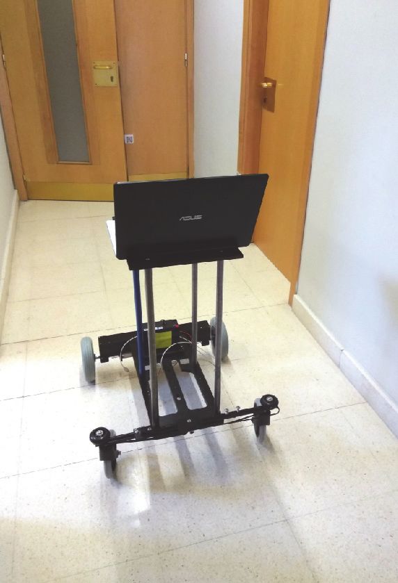
Journal of Sensors 3

how the method also includes a process to automatically
detect when a whole round has been completed. This is done
in order to allow a nonqualified person to be able to calibrate
the robot without taking into account if the round has been
completed or not. This automatic whole round detection is
based on a module of ultrasound sensors (HC-SR04).The
measuring range of this sensor is 2cm-2m, and it is connected
to a 5V power source.
 At this point it is important to emphasize that the
accuracy of the ultrasounds distance measurements is not
important, but instead the profile of the received measure- Right
 Wheel
ments when the robot is turning around. The most important
issue is therefore that the scenario must not be “periodic” Figure 1: Robot scheme while turning with left wheel stopped.
or the obstacles found should not be uniform. Let us name
the sequence of distance values obtained from the ultrasound
sensor [ ], with being the number of pulses read from the
encoder, when the robot has exceeded one round. The length where, as mentioned above, pulses/rev is a constant to
of the signal will be noted as , and so, the autocorrelation translate wheel turns to pulses.
function will have a length of 2 − 1 and can be defined as Using Equation (10) yields

 ( ) = ∑ [ ] [ − ]
 1
 = = (11)
 (9) 1
 = argmax ( ) −
 ∈[ , ]
 The movements involved in this test suffer from one
 where and are the start and end point, respectively, of problem: stopped wheels need low levels of friction to
a window around − ̂ and where ̂ is the theoretical number perform the circular movement of the robot but enough
of pulses that the robot needs to complete one turn, obtained friction to take the wheel to the same point. When the test is
from and . will then reflect the actual number done on a slippery floor, a small piece (see Figure 2) has been
of pulses to complete a whole round. In our case, we have designed to achieve this goal, so that now the wheel pivots
selected and to have a window of ±0.45 ̂ pulses. Figure 6 on that piece over an axial bearing. Figure 3 illustrates the
and the zoomed Figure 7 show the distances from the sensor situation of the wheel during the test: the wheel, the piece,
as a function of the pulses of the encoder of the moving wheel. and the axial bearing are visible.
It is apparent that the distances measured in the peaks are not The incorporation of this small piece implies that the
equal and we are not even interested in the extent of error in distance travelled not only is based on the effective wheelbase,
the real distance to the obstacles. What we are truly interested but also depends on the height of the piece. We can consider
in is the autocorrelation of the sequence that can estimate that the distance travelled is = 2 where 0 is the distance
when the robot has completed a round. Figure 8 shows the from the point of contact between the piece and the floor to
autocorrelation for the distances read from the ultrasound the point of contact with the opposite wheel (the wheel that
sensor, showing where the peak is located, which gives the is the one not stopped). Nevertheless, as the same piece is
point in the sequence that corresponds to a whole round. located first under one wheel and subsequently on the other,
 This method avoids errors in the annotation of the pulses the distance per lap is going to be the same, and equation (11)
per round. In fact, the robot turns around for several laps, and holds.
the pulses are annotated automatically, obtaining and .
 2.3. Estimation of . The robot’s movements while attempt-
2.2. Estimation of . The proposed calibration method aims ing to travel in a straight line are illustrated in Figure 4.
to reduce the time required to perform a calibration. We The actual distance from A to B is not the output of the
are seeking the actual , , and . The first experiment encoder corrected by the conversion factor . However, if
looks for the relation = / : the robot will describe the robot’s orientation is kept below a given threshold, the
a circular path with the left wheel stopped for rounds. This maximum deviation of that measurement can be controlled.
is then repeated with the right wheel stopped for another For example, if the orientation remains below 1∘ , then the
 rounds. Figure 1 shows the robot while turning with a maximum deviation remains less than 0.02%, and, for 2∘ ,
stopped left wheel. The distance travelled, , in each round, less than 0.06%. Those deviations can be accepted for our
can be expressed in different ways depending on the effective experiments and we will analyze the robot’s orientation to
wheelbase and the number of pulses in each round 1 and reject the measurements where the maximum deviation of
 1 : orientation is greater than a given threshold.
 1 1 The right wheel is taken as a reference, and is corrected
 = 2 = = (10) by the factor . In the second experiment, a straight motion
 for 3 m is performed by the robot, and the number of pulses

4 Journal of Sensors

 A B
 Figure 4: Movement diagram.

 parameters are obtained. UMB calibration was also used to
 compare our method with the most popular one used to
 Figure 2: Bearing base.
 calibrate differential robots without highly accurate distance
 sensors. Our robot software has 3 parameters to adjust. They
 are set before starting each calibration method:
 190
 = = = 3.80 /
 157.2
 (17)
 = 1,
 = 590

 3.1. UAH Calibration 1. The first experiment was carried out
 Figure 3: Wheel detail. with the robot platform shown in Figure 5. First, with the
 left wheel stopped, the robot performed a given number of
 rounds and the experiment was then repeated for a stopped
of the right wheel, 2 , with the actual distance travelled 3 right wheel.
gives the conversion factor from pulses to mm as Figure 6 shows the output of the ultrasound sensor for
 3 9 turns and only two periods are plotted in Figure 7. It is
 = (12) important to ensure that the scenario is not symmetrical in
 2 order to get the proper period. In our case, because of the
 limited sensor range of 2 metres, the scenario must not be
The actual is given by
 too large.
 The number of pulses when the left wheel is stopped per
 = (13)
 turn (period) 1 is
and, in our case, = 152.7 pulses/rev.
 is obtained by means of and : 1 = {951.1, 952.0, 951.0} (18)
 1 + for three iterations, and as can be seen, the variance for
 = (14)
 2 different iterations is low. When the right wheel is stopped,
 1 is
Returning to Equation (9) and taking into account that a
small piece was introduced the value of 0 is given by 1 = {944.0, 943.0, 943.0} (19)
 1 also for three iterations of the experiment.
 0 = (15)
 2 We then obtained the effective wheelbase factor for
 movements with a stopped wheel, so the robot performed
We are interested in obtaining . To that end, we performed movements as was explained previously. We obtained 1 =
a movement turning over one stopped wheel and then
 951 pulses and 0 = 478 pulses, so
turning with both wheels at the same speed but in opposite /2

directions, taking into account the number of pulses required
to complete a turn with the stopped wheel 0 and the = 1.0053. (20)

number of pulses when turning with the two wheels at the Several iterations of these experiments were carried out,
same speed 0 . The factor to obtain is and the raw data for 5 experiments of each can be found at
 /2
 http://agamenon.tsc.uah.es/Investigacion/gram/papers/Sensors/
 2 ∗ 0 /2 Results.zip.
 = = (16) Taking the mean value
 0 0

 1
 = = = 1.007 (21)
3. Experiments 1

In this section, we present one of the experiments to provide In order to perform the second experiment, the factor
a better understanding of the method involved and how the must be included in the robot’s odometry, so we set up the
Journal of Sensors 5

 150

 100

 distance (cm)
 50

 0
 0 500 1000 1500 2000
 pulses

 Figure 7: Zoom sensor output over the left wheel.

 Figure 5: Robotic platform. ×10 7
 7

 160 6

 140
 5
 120
distance (cm)

 100 4
 (=G2 )

 80
 3
 60
 40 2
 20
 1
 0
 0 1000 2000 3000 4000 5000 6000 7000 8000
 0
 pulses 0 2000 4000 6000 8000 10000 12000 14000 16000
 pulses
 Figure 6: Sensor output rotating over the left wheel.
 Figure 8: Sensor output autocorrelation sequence.

new in the robot software or automatically update it if the
calculation is done on-board.
 A 3m long motion is then performed and the number 3.2. UMB Calibration. The V from UAH calibration 1
of pulses in several iterations is illustrated in Table 1, where is used to perform the UBM calibration [18]. The setup
the number of pulses for the distance actually travelled gives parameters are
the factor . The maximum deviation in orientation is also
considered in order to discard results with deviations more
than 1∘ . 188.55
 From the results in Table 1 we obtain = 3.86 mm/pulse. = = = 3.88
 152.7
 The wheelbase distance 0 can be obtained from
 (24)
 = 1,
 2 0 = 1 ⋅ (22)
 = 590.
and the can be calculated using the value found above:

 2 = 1 ⋅ (23) The UMB method [18] was carried out for a square of

 = 2 m (as was suggested in [22]) for 5 rounds clockwise
which gives, = (951.3⋅3.86⋅1.0053)/2 = 586.5 mm, from and 5 counterclockwise, and the final point deviations of each
Equation (13) = 187.61 mm and from Equation (14) = movement were recorded. Our robot platform is almost 1 m
0.9924, where the used nominal diameter was = 190 long and a larger free scenario was not viable.
mm and the new average of the diameters is V = 188.55 The results for the error centres of gravity for clockwise
mm. We do not use V but it will be necessary to perform ( , , , ) and counterclockwise rounds ( , , , )
a calibration from [18] for comparison. are

6 Journal of Sensors

 Table 1: Results from the second experiments.

 2 distance max( )
Iteration
 (Pulses) (mm) (degrees) (mm/pulse)
1 795 3078 0.75 3.87
2 795 3068 0.93 3.86
3 795 3068 0.75 3.86
4 795 3070 0.76 3.86

 1 5 200
 , V/ = ∑ ,cV/
 5 =1 100
 (25) 0
 5
 1

 Error in y (mm)
 −100
 , = ∑ , V/
 5 =1 −200
 −300
where the error is the difference between the actual absolute −400
position of the robot and the calculated position.
 −500
 −600
 = − −700
 0 50 100 150
 = − Error in x (mm)

 , = 24.0 UAH
 (26) UMB
 , = −34.6 Before Calibration

 Figure 9: Error from different calibrations (3m- -3m).
 , = −65.6

 , = 53.0 before calibration, with the calibration method UAH and for
 UMBmark. The error in Table 2 is basically due to the error
 Using the equations from [18], in the wheel diameters and the error in Table 3 is affected by
 , + , 180∘ the wheel diameters and .
 = (27) Figure 9 shows the error before calibration, with the UMB
 −4 method calibration and the method proposed in this paper
in degrees, the results above give = 0.298 and (UAH). Because of the simplicity of our method, we used it
 instead of the UMB. Most of the measurements in the method
 , − , 180∘ proposed herein are done on-board, and the initial point is
 = (28) not important in most of the movements.
 −4
in degrees, = 0.642, so = 591.96 mm and = 1.003. 5. Conclusions
 If the correction from [22] is included, a slight change is
obtained: = 591.98 mm. The paper presents a new method for differential drive robot
 calibration. One of its main contributions is that the free
4. Validation space needed to perform the calibration in our method is
 very small. Furthermore, only one manual measurement
In [18], the same experiment used for calibration is repeated is required with our method, which can be repeated in
after calibration in order to test the method. This validation order to check the correctness, but checking the maximum
process needs a large space to perform the test. In [20, orientation makes discarding wrong measurements easy. The
21], only simulation results are presented to compare the most complicated part of the calibration method can be done
methods. on-board. If a calibrated distance sensor is available, the
 In order to test the results of calibration, the journey whole method can be implemented on-board.
involved travelling along a 3 m long path, followed by a turn Our results are very close to those obtained with the UMB
through an angle of and then returning for 3 m. These method, so we use our method because of its simplicity in
experiments were repeated thirty times to obtain statistical performing the calibration.
conclusions. Tables 2 and 3 show the error in mm in the Future work will focus on extending the method dis-
 and coordinates and in radians for the orientation cussed here to nondifferential robots, while emphasising the
Journal of Sensors 7

 Table 2: Validation results 3m.

 Method
 (mm) (mm) (rads)
 Mean Error 62.33 96.00 0.0046
Before cal.
 Std. Dev. 7.09 14.53 0.0036
 Mean Error 6.75 63.25 -0.041
UAH Cal.
 Std. Dev. 1.26 15.20 0.0056
 Mean Error 4.75 60.01 -0.0338
UMB Cal.
 Std. Dev. 1.70 14.13 0.0034

 Table 3: Validation results 3m- -3m.

 Method
 (mm) (mm) (rads)
 Mean Error 99.76 -553.07 0.0875
Before cal.
 Std. Dev. 14.89 55.61 0.0178
 Mean Error 70.03 -18.29 0.0037
UAH Cal.
 Std. Dev. 9.66 49.57 0.0152
 Mean Error 76.38 -9.58 -0.019
UMB Cal.
 Std. Dev. 4.60 33.35 0.028

low-cost design. A study of Ackerman-type or multiwheel [2] F. Arvin, J. Murray, C. Zhang, and S. Yue, “Colias: An
traction robots will therefore be performed to enable a simple autonomous micro robot for swarm robotic applications,”
autocalibration method without any space restrictions, as International Journal of Advanced Robotic Systems, vol. 11, no.
presented in this study. 1, p. 113, 2014.
 Low-cost camera odometry and the method proposed [3] F. B. V. Benitti, “Exploring the educational potential of robotics
here are also an interesting research line. This means that, in schools: A systematic review,” Computers & Education, vol.
once the encoder odometry has been calibrated, the visual 58, no. 3, pp. 978–988, 2012.
odometry from low-cost cameras can be joined to feed back [4] F. M. López-Rodrı́guez and C. Federico, “Andruino-a1: Low-
 cost educational mobile robot based on android and arduino,”
the whole system.
 Journal of Intelligent & Robotic Systems, vol. 81, no. 1, pp. 63–76,
 2016.
Data Availability [5] A. Elatta, L. Gen, and F. Zhi, “An overview of robot calibration,”
 Information Technology Journal, vol. 3, no. 1, pp. 74–78, 2004.
http://agamenon.tsc.uah.es/Investigacion/gram/papers/ [6] A. Nubiola and I. A. Bonev, “Absolute calibration of an ABB
Sensors/Results.zip includes all the data and instructions to IRB 1600 robot using a laser tracker,” Robotics and Computer-
verify or replicate the experiments to other researchers. Integrated Manufacturing, vol. 29, no. 1, pp. 236–245, 2013.
 [7] J. J. Leonard and H. F. Durrant-Whyte, Directed Sonar Sensing
Conflicts of Interest for Mobile Robot Navigation, Kluwer Academic Publishers,
 Norwell, MA, USA, 1992.
The authors declare that they have no conflicts of interest. [8] J. Qian, B. Zi, D. Wang, Y. Ma, and D. Zhang, “The design and
 development of an Omni-Directional mobile robot oriented to
 an intelligent manufacturing system,” Sensors, vol. 17, no. 9, 2017.
Acknowledgments [9] A. Traslosheros, J. M. Sebastián, J. Torrijos, R. Carelli, and E.
 Castillo, “An inexpensive method for kinematic calibration of a
This work was partially supported by the University of parallel robot by using one hand-held camera as main sensor,”
Alcalá research programme with projects CCG2016/EXP- Sensors, vol. 13, no. 8, pp. 9941–9965, 2013.
045 and CCG2016/EXP-042 and by the project PREPEATE, [10] G. Du and P. Zhang, “Online robot calibration based on vision
with reference TEC2016-80326-R, of the Spanish Ministry of measurement,” Robotics and Computer-Integrated Manufactur-
Economy, Industry and Competitiveness. ing, vol. 29, no. 6, pp. 484–492, 2013.
 [11] T. Messay, R. Ordóñez, and E. Marcil, “Computationally effi-
References cient and robust kinematic calibration methodologies and
 their application to industrial robots,” Robotics and Computer-
[1] M. Rubenstein, C. Ahler, N. Hoff, A. Cabrera, and R. Nagpal, Integrated Manufacturing, vol. 37, article no. 1350, pp. 33–48,
 “Kilobot: A low cost robot with scalable operations designed for 2016.
 collective behaviors,” Robotics and Autonomous Systems, vol. 62, [12] Y. Zeng, W. Tian, and W. Liao, “Positional error similarity
 no. 7, pp. 966–975, 2014. analysis for error compensation of industrial robots,” Robotics

8 Journal of Sensors

 and Computer-Integrated Manufacturing, vol. 42, pp. 113–120,
 2016.
[13] G. Gang, L. Tong, C. Ming, J. Q. Xuan, and S. H. Xu, “Review
 on kinematics calibration technology of serial robots,” Interna-
 tional Journal of Precision Engineering and Manufacturing, vol.
 15, no. 8, pp. 1759–1774, 2014.
[14] S. Qian, K. Bao, B. Zi, and N. Wang, “Kinematic calibration of a
 cable-driven parallel robot for 3D printing,” Sensors, vol. 18, no.
 9, 2018.
[15] A. Martinelli, N. Tomatis, and R. Siegwart, “Simultaneous
 localization and odometry self calibration for mobile robot,”
 Autonomous Robots, vol. 22, no. 1, pp. 75–85, 2007.
[16] A. Censi, A. Franchi, L. Marchionni, and G. Oriolo, “Simultane-
 ous calibration of odometry and sensor parameters for mobile
 Robots,” IEEE Transactions on Robotics, vol. 29, no. 2, pp. 475–
 492, 2013.
[17] Y. Hwang and J. Lee, “Robust 2D map building with motion-
 free ICP algorithm for mobile robot navigation,” Robotica, vol.
 35, no. 9, pp. 1845–1863, 2017.
[18] J. Borenstein and L. Feng, “Correction of systematic odometry
 errors in mobile robots,” in Proceedings of the 1995 IEEE/RSJ
 International Conference on Intelligent Robots and Systems, vol.
 3, pp. 569–574, IEEE, August 1995.
[19] J. Borenstein and L. Feng, “Measurement and correction of sys-
 tematic odometry errors in mobile robots,” IEEE Transactions
 on Robotics and Automation, vol. 12, no. 6, pp. 869–880, 1996.
[20] T. Abbas, M. Arif, and W. Ahmed, “Measurement and cor-
 rection of systematic odometry errors caused by kinematics
 imperfections in mobile robots,” in Proceedings of the 2006
 SICE-ICASE International Joint Conference, pp. 2073–2078,
 IEEE, Republic of Korea, October 2006.
[21] A. Bostani, A. Vakili, and T. A. Denidni, “A novel method to
 measure and correct the odometry errors in mobile robots,”
 in Proceedings of the IEEE Canadian Conference on Electrical
 and Computer Engineering, CCECE 2008, pp. 897–900, IEEE,
 Canada, May 2008.
[22] K. Lee, C. Jung, and W. Chung, “Accurate calibration of
 kinematic parameters for two wheel differential mobile robots,”
 Journal of Mechanical Science and Technology, vol. 25, no. 6, pp.
 1603–1611, 2011.
[23] Y. Maddahi, “Calibration of mobile robotic systems: a pilot
 study,” Proceedings, vol. 2, no. 3, p. 141, 2018.

International Journal of

 Rotating Advances in
 Machinery Multimedia

 The Scientific
Engineering
 Journal of
 Journal of

Hindawi
 World Journal
 Hindawi Publishing Corporation Hindawi
 Sensors
 Hindawi Hindawi
www.hindawi.com Volume 2018 http://www.hindawi.com
 www.hindawi.com Volume 2018
 2013 www.hindawi.com Volume 2018 www.hindawi.com Volume 2018 www.hindawi.com Volume 2018

 Journal of

 Control Science
 and Engineering

Advances in
Civil Engineering
Hindawi Hindawi
www.hindawi.com Volume 2018 www.hindawi.com Volume 2018

 Submit your manuscripts at
 www.hindawi.com

 Journal of
Journal of Electrical and Computer
Robotics
Hindawi
 Engineering
 Hindawi
www.hindawi.com Volume 2018 www.hindawi.com Volume 2018

 VLSI Design
Advances in
OptoElectronics
 International Journal of

 International Journal of
 Modelling &
 Simulation
 Aerospace
Hindawi Volume 2018
 Navigation and
 Observation
 Hindawi
 www.hindawi.com Volume 2018
 in Engineering
 Hindawi
 www.hindawi.com Volume 2018
 Engineering
 Hindawi
 www.hindawi.com Volume 2018
 Hindawi
www.hindawi.com www.hindawi.com Volume 2018

 International Journal of
International Journal of Antennas and Active and Passive Advances in
Chemical Engineering Propagation Electronic Components Shock and Vibration Acoustics and Vibration
Hindawi Hindawi Hindawi Hindawi Hindawi
www.hindawi.com Volume 2018 www.hindawi.com Volume 2018 www.hindawi.com Volume 2018 www.hindawi.com Volume 2018 www.hindawi.com Volume 2018

You can also read