American Eagle Outfitters: Quantum III - Sam Jannotti Structural Option
←
→
Page content transcription
If your browser does not render page correctly, please read the page content below
American Eagle Outfitters: Quantum III

                          Sam Jannotti
                          Structural Option
                          The Pennsylvania StateUniversity
                          M Kevin Parfitt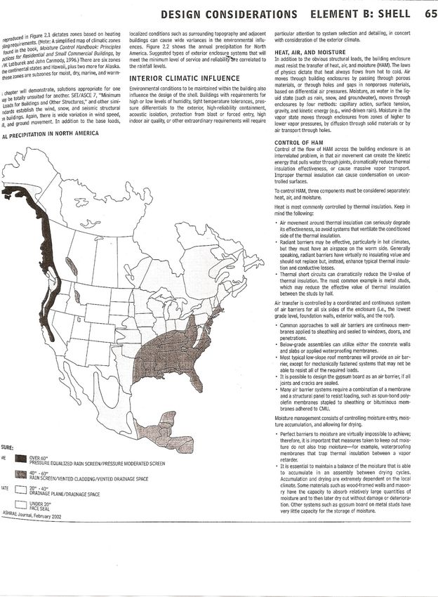
Pi
ttsburgh,PA
T
hePr
ojec
tTea
m Bui
l
dingS
tat
is
ti
cs
Owner : Amer i
canE agleOutfit t
ers Locat
ion:19HotMetalSt
reet
,Pit
tsburgh,PA
Archit
ect:TheDes i
gnAl l
i
anceAr chi
tects Occupancy:Offic e
Cons t
ruct
ionMa nager /
Dev el
oper :TheSofferOrga
niz
ati
on Si
ze:5s t
ori
esand150,
000sq.ft
.
St
ruc t
uralEngineer:Atlanti
cEngineeringSer
vic
es Constr
ucti
onDa t
es:May2007-October2008
ME PEngineer:TowerE ngineering Cost
:$16mi l
li
onBuil
dingShell
andCor e
Ci
v i
l:TheGa t
ewa yE ngineers
,Inc. Deli
veryMethod:Desi
gn-Bi
d-Bui
ld
Landscape:Env i
ronment alPla
nni ngandDesign
L
ight
inga
ndE
lec
tri
cal
S
truc
tur
e 277/480V, 3pha s
e ,4wi r
es ys
tem droppeddown
Widefla ngec olumns ,bea ms,andgir
der swit
hc omposi
te toa208/ 120Vs ystem
li
ghtweightc onc reteons teeldeck Tra
ns f
or merspresenta teachlevelinpanelr
oom
Typic
alba y
sa re30’ ona nopenpl an Atleasttwopa nelsforea chvolt
a gelevel
oneach
Bathr
ooms ,mec hanica l
s pac
es ,a
ndelev at
ors/
egressl
ocat
ed floor
incenterofpl an,a l
sohous ingtwov erti
calt
russest
o Onlylighti
nginc l
udedi nc ontr
actisemergency
counteractlateralloads andegr essfluor escenttubes,e x
itsi
gns,a
nd
60tona ugerc astpilesa nd3000ps ispreadfoundati
ons loadinga r
easwi t
hmet alhali
demount edon
wa l
k waysandint reesforaestheticpur
poses
Eachfloorl i
ghtingtobef urni
shedbyt enant
Ar
chi
tec
tur
e
Tr
ansparencythroughc urtai
nwa ll
s,mas
sshownthrough Mec
hani
cal
bri
ckfacade
Twoa i
rhandli
ngunitspr
ovidi
ng120,000CFM
Compositealuminum pa nelsandcorni
ceuni
fybui
lding
total
fa
cades
30%or36,000CF Moutsi
dea i
r
Openplanforfuturetena ntfit-
out
Si
ngleverti
calt
russfull
yv is
ibl
ethroughcurt
ainwal
l, Hea tr
ecover
y/entha
lpywheelsoper
ateat64%
demons t
rati
ngbuildings tr
uctur
e effic i
encyforcool
ingand77%effic ienc
yfor
heati
ng
Structural
ht
tp:
//
www.
engr
.psu.
edu/
ae/
thesi
s/por
tf
oli
os/
2008/
smj
167/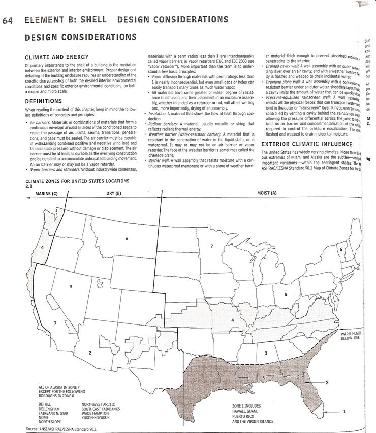
Sam Jannotti                                       American Eagle Outfitters
                                                                      Quantum III
                                                         Pittsburgh, Pennsylvania

Executive Summary

      American Eagle Outfitters: Quantum III is a steel framed office building located in the
South Side Works of Pittsburgh, Pennsylvania. Design changes were introduced including
moving the building to Oakland, California and increasing it’s profile by two stories. This report
analyzes the structure of this building and it’s adequacy on the basis of currently accepted
national codes, economy, and flexibility.
      Lateral systems were designed to withstand seismic category E design forces. This was
achieved through numerous framing layout iterations and a preliminary beam, column, and brace
design. Torsion, redundancy, and p-delta effects were all taken into consideration for design.
The completed preliminary analysis was checked for story drift limitations for both wind and
seismic forces to demonstrate the difference in Pittsburgh, Pennsylvania and Oakland, California
requirements.
      The redesign of building shell elements was completed as well. Window assemblies were
analyzed for their mechanical and architectural properties. A double glazed window with a
spectrally selective tint was chosen. Satisfying a wide range of aesthetic uses, it also provides a
U-factor of 0.3, greatly reducing heating and cooling load losses for QIII. The building scale
was changed from 67’ to over 96’ tall, possibly requiring rescaling of building elements.
Additionally, shell elements were changed to better reflect the aura of Oakland, California.
      Mechanical system design was performed for the existing and proposed Quantum
buildings. They were compared based on their overall efficiency and heat loss through curtain
wall systems. The added two floors greatly increased heating and cooling loads, so efficiency
was calculated based on relative percentages.
      The following report describes the considerations and details that composed the studies
outlined above.

                                          Page 1 of 95
Sam Jannotti                                       American Eagle Outfitters
                                                                      Quantum III
                                                         Pittsburgh, Pennsylvania

Acknowledgements

Completing this senior thesis could not have happened if it weren’t for the help and patience
given by all these family members, friends, design professionals, and firms:

     To my family:
     You taught me how to appreciate life and the people around me. Thank you for your
     continuing support and always keeping an open ear.

     To my friends:
     Thanks to Steve Reichwein for dealing with my one thousand questions per week, Jason
     Sambolt for his help with Trane TRACE 700 and mechanical design, and Gary Newman
     for making me step back and breathe once in a while. To the best time of our life, five
     years and counting!

      Atlantic Engineering Services:                      The Soffer Organization
      Tim Jones
      Andy Verrengia
      John Schneider                                      Tower Engineering
      Chris Kim

      American Eagle Outfitters                           The Gateway Engineers, Inc.

     The Design Alliance Architects                       Environmental Planning and Design

                                    Finally, To the AE Faculty:
                                            Kevin Parfitt
                                           Andres Lepage
                                             Ali Memari
                                           Robert Holland
                                   The entire AE Faculty and Staff

                                         Page 2 of 95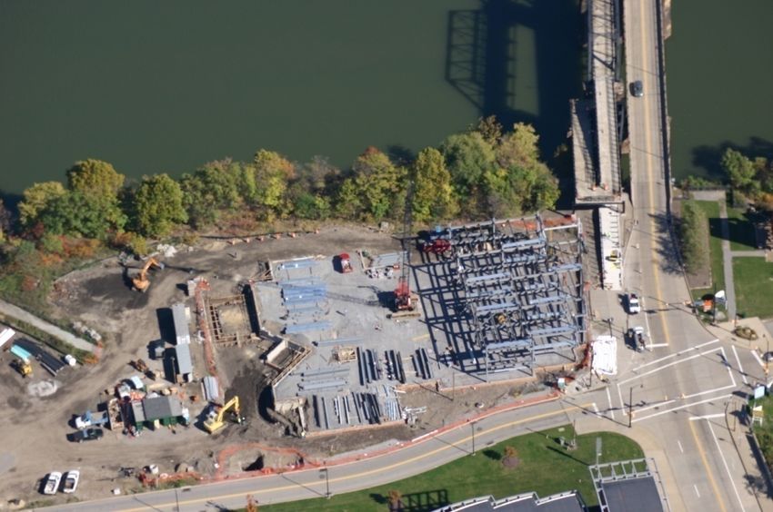
Sam Jannotti                                     American Eagle Outfitters
                                                                   Quantum III
                                                      Pittsburgh, Pennsylvania

Table of Contents

    Thesis Abstract
    Executive Summary                                                 1
    Acknowledgements                                                  2
    Table of Contents                                                 3
    List of Figures                                                   5
    1. Introduction                                                   7
    2. Building Background                                            8
        2.1 General Information                                       8
        2.2 Architectural Overview and History                        9
        2.3 Building Envelope Architecture                            9
        2.4 Building Plan Architecture                               10
        2.5 Zoning                                                   10
        2.6 Structural Systems                                       10
        2.7 Mechanical System                                        11
        2.8 Construction and Management                              11
        2.9 Electrical Systems                                       11
        2.10 Lighting Systems                                        11
        2.11 Fire Protection                                         12
        2.12 Transportation                                          12
        2.13 Communications                                          12
        2.14 Project Team                                            13
3. Structural Redesign                                               14
        3.1 Existing Structural Systems                              14
                3.1.1 Geotechnical and Foundation Concerns           14
                3.1.2 Floor Framing                                  15
                3.1.3 Gravity System Columns                         17
                3.1.4 Lateral Load Resisting Elements                17
                3.1.5 3-D Model Images                               20
        3.2 Codes and Material Properties                            21
                3.2.1 Codes and Referenced Standards                 21
                3.2.2 Material Properties                            21
        3.3 Existing System Loads and Criteria                       22
                3.3.1 Load Cases and Combinations                    22
                3.3.2 Dead Loads                                     23
                3.3.3 Wall Loads                                     23
                3.3.4 Live Loads                                     24
                3.3.5 Existing Building Wind Criteria                25
                3.3.6 Existing Building Seismic Criteria             25
        3.4 Basis for Structural Redesign                            26
                3.4.1 Gravity System                                 26
                3.4.2 Lateral Force Resisting Elements               27
                3.4.3 Design Goals and Scope                         27

                                       Page 3 of 95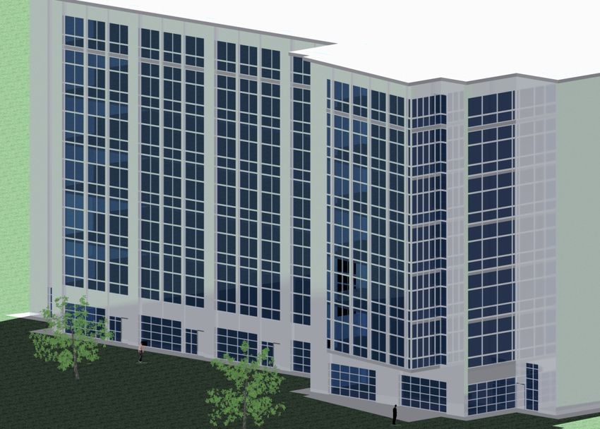
Sam Jannotti                                    American Eagle Outfitters
                                                                  Quantum III
                                                     Pittsburgh, Pennsylvania

       3.5 Proposed Gravity System                                  28
               3.5.1 Gravity Framing                                28
               3.5.2 Gravity Frame Detailing                        28
       3.6 Proposed Lateral Frame Design                            29
               3.6.1 New Wind Criteria                              29
               3.6.2 Wind Design Methodology                        29
               3.6.3 Wind Story Shears and Overturning Moments      30
               3.6.4 Wind Induced Story Drift                       32
               3.6.5 New Seismic Criteria                           32
               3.6.6 Additional Lateral Frames                      33
                        3.6.6.1 Vertical Truss Elevations           34
               3.6.7 Seismic Design                                 35
                        3.6.7.1 Seismic Story Shears                35
                        3.6.7.2 Design A                            36
                        3.6.7.3 Design B                            37
                        3.6.7.4 Continuing Design                   40
                        3.6.7.5 Redundancy and Irregularities       41
       3.7 Impact of Redesign                                       41
       3.8 Structural Conclusion                                    41
4. Architectural Breadth                                            42
       4.1 Existing Building Architecture and Proposed Changes      42
       4.2 Possible Frame Locations                                 45
       4.3 Final Frame Layout                                       45
       4.4 Shell Redesign                                           46
               4.4.1 Oakland Architecture                           46
               4.4.2 Façade Assemblies                              47
                4.4.3 Façade Redesign                               48
5. Mechanical Breadth                                               49
       5.1 Design Goals                                             49
       5.2 Existing System                                          49
       5.3 New Shell Assemblies                                     50
       5.4 Oakland Climatic Data                                    51
       5.5 Results                                                  51
       5.6 Mechanical Breadth Conclusions                           55
6. Conclusion                                                       56
Appendix A – Gravity Loads                                          57
       A.1 Dead Loads                                               57
       A.2 Live Loads                                               60
Appendix B – Lateral Loads                                          61
       B.1 Wind Loads                                               61
       B.2 Seismic Loads                                            69
Appendix C – Architectural Supplements                              87
Appendix D – Mechanical Breadth                                     90
Bibliography                                                        91

                                      Page 4 of 95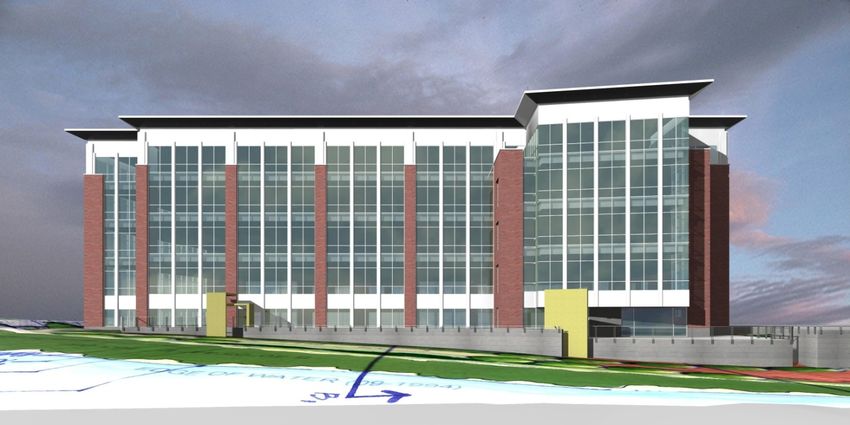
Sam Jannotti                                     American Eagle Outfitters
                                                                   Quantum III
                                                      Pittsburgh, Pennsylvania

List of Figures

Figure 1 – Location of AEO: QIII                                                  8
Figure 2 – View of South Side Works                                               9
Figure 3 – North Perspective with Branding Wall                                   9
Figure 4 – Ongoing QIII Construction by Monongahela River                         14
Figure 5 – Typical Architectural Floor Plan                                       15
Figure 6 – Typical Floor System Construction                                      15
Figure 7 – Typical Bay                                                            16
Figure 8 – Typical Floor Framing                                                  16
Figure 9 – Vertical Truss Locations                                               17
Figure 10 – Vertical Trusses A, B and C (VT-A, B, C)                              18
Figure 11 – Brace Connection Detail                                               18
Figure 12 – Vertical Trusses D and E (VT-D, E)                                    19
Figure 13 – 3D View from West Building Corner                                     20
Figure 14 – 3D View from East Building Corner                                     20
Figure 15 – Dead Loads                                                            23
Figure 16 – Mechanical Unit Surface Loads                                         23
Figure 17 – Gravity Member Comparison                                             28
Figure 18 – Wind Analysis Methodology                                             29
Figure 19 – North-South Wind Shears and Overturning Moments                       30
Figure 20 – East West Wind Shears and Overturning Moments                         31
Figure 21 – Existing and Potential New Vertical Truss Locations                   33
Figure 22 – Proposed Truss Elevations                                             34
Figure 23 – West Elevation and NT-B and D                                         34
Figure 24 – Seismic Base Shears                                                   35
Figure 25 – Seismic Base Shear Comparison                                         36
Figure 26 – Design B Frame Locations                                              37
Figure 27 – Design B VT-B and D Elevation                                         37
Figure 28 – Design B Methodology                                                  38
Figure 29 – Stress Ratio Key                                                      39
Figure 30 – NT-B and NT-D Elevation                                               39
Figure 31 – Vertical Truss Elevations Under Controlling Loads                     40
Figure 32 – North QIII Façade                                                     42
Figure 33 – Existing and New Truss Locations                                      43
Figure 34 – North Elevation and NT-A                                              44
Figure 35- East Elevation and NT-E                                                44
Figure 36 - West Elevation and VT-B and D                                         45
Figure 37 – Final Frame Layout                                                    45
Figure 38 – North Building Elevation for Existing and New Quantum III             46
Figure 39 – Mixed Climate Wall Assembly (Architects, 2007)                        47
Figure 40 – North Façade Rendering                                                48
Figure 41 – Window Transmitting Properties (Architects, 2007)                     50
Figure 42 – Window Assembly U-Factors                                             50

                                       Page 5 of 95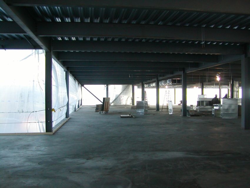
Sam Jannotti                                   American Eagle Outfitters
                                                                 Quantum III
                                                    Pittsburgh, Pennsylvania

Figure 43 – TRACE Existing Cooling Coil Results                                 51
Figure 44 – TRACE Existing Heating Coil Results                                 52
Figure 45 – TRACE New Cooling Coil Results                                      53
Figure 46 – TRACE Heating Coil Results                                          54
Figure 47 – Dead Loads                                                          57
Figure 48 – Mechanical Unit Surface Loads                                       57
Figure 49 – Roof Composite Roof Deck                                            58
Figure 50 – Typical Floor Composite Deck                                        59
Figure 51 – Roof Composite Deck (United Steel Deck, 2003)                       60
Figure 52 – Wind Input                                                          61
Figure 53 – Wind Pressure Coefficients                                          62
Figure 54 – Wind q Factor Calculation                                           63
Figure 55 – MWFRS Design Pressures                                              64
Figure 56 – MWFRS Design Pressures                                              65
Figure 57 – Wind Forces and Overturning Moments - E-W Wind                      66
Figure 58 – Wind Forces and Overturning Moments – N-S Wind                      67
Figure 59 – Wind Story Drift                                                    68
Figure 60 – Seismic Design Methodology                                          74
Figure 61 – RAM Building Weights (1)                                            74
Figure 62 – Building Masses (1)                                                 75
Figure 63 – Seismic Base Shear (2)                                              75
Figure 64 – Seismic Base Shear Comparison (2)                                   76
Figure 65 – Preliminary Frame Relative Rigidities (3)                           76
Figure 66 – Frame Preliminary Sizing (3-7)                                      78
Figure 67 – Actual Frame Deflection Data from ETABS (13)                        79
Figure 68 – Frame Actual Relative Rigidities (13)                               80
Figure 69 – Max Shear and Moment                                                81
Figure 70 – SCBF Design Spreadsheet - Input                                     81
Figure 71 – SCBF Inverted V Beam Design                                         83
Figure 72 – EBF Beam Input and Design                                           83
Figure 73 – EBF Link Design                                                     84
Figure 74 – Seismic Drift                                                       85
Figure 75 – Wind and Seismic Overturning Moments                                86
Figure 76 – US Climate Zones                                                    87
Figure 77 – US Rainfall Data                                                    88
Figure 78 – Shell Design                                                        89
Figure 79 – TRACE Results                                                       93
Figure 80 – TRACE Results                                                       94

                                     Page 6 of 95
Sam Jannotti                                         American Eagle Outfitters
                                                                        Quantum III
                                                           Pittsburgh, Pennsylvania

1. Introduction

       The Architectural Engineering Senior Thesis is the culmination of five years of foundation
course work, resulting in a presentation and report that outline all facets of engineering study.
The year long class involves analyzing the existing building, proposing a design change, and
evaluating the new design. The class is conducive to gaining invaluable experience in typical
engineering practices as a stepping stone to entering the industry.
       Beginning in the fall semester, students analyze the building critically—from gravity loads
to lateral force resisting systems and even seismic design details. Students build on their
knowledge of the building through three technical reports that each focus on a separate aspect of
architectural engineering. By the end of the fall semester, a significant foundation is placed,
allowing each student to branch off into a depth study consistent with their focus in the
Architectural Engineering curriculum.
       The spring semester is composed of following a task schedule to achieve a design worthy
of an engineer in training. It is highly dependent on the student’s ability of to meet self-set
deadlines throughout the semester. The requirement is an in-depth study reflecting knowledge
the student obtained their respective focus. On top of this, they must demonstrate their wide
spectrum of architectural engineering knowledge through two “breadth” studies. These result in
a capstone final report and presentation to a faculty jury.

       This report represents my five years of study in the Architectural Engineering curriculum.
It is, without doubt, the capstone of my hard work within the program and represents my ability
to learn engineering design methods both in class and independently. In addition, this report
contains the results of a full year of study on American Eagle Outfitters: Quantum III. The
report is divided into depth and breadth sections with appendices relating to each for ease of
reference.
        The primary goal of this report is to obtain a preliminary lateral frame design in Oakland,
California. This was assessed based on effectiveness, constructability, and economy. Breadth
areas were architecture and mechanical engineering. Wall assemblies were also considered and
related to both breadths.
        All materials submitted as part of the final report and senior thesis are available online at:
http://www.engr.psu.edu/ae/thesis/portfolios/2008/smj167/. The report and all materials posted
online and presented in this report are for educational purposes only and represent Sam Jannotti’s
personal views and design work. These materials in no way reflect American Eagle Outfitter’s
corporate or mercantile plans and were presented for the sole purpose of education.

                                           Page 7 of 95
Sam Jannotti                                        American Eagle Outfitters
                                                                       Quantum III
                                                          Pittsburgh, Pennsylvania

2. Building Background

2.1 General Information

      Quantum III is a product of the continuing expansion of American Eagle Outfitters
Corporate Headquarters in the South Side of Pittsburgh, Pennsylvania. It is a genuine combi-
nation of structural design for flexibility and the blending of architectural tastes of the existing
South Side of Pittsburgh with that of the developer, The Soffer Organization. At one end of Hot
Metal Bridge, and bordering the Monongahela River lies Quantum III. The existing office
building is five stories tall and contains loading, fire pump, and generator rooms on the first
floor. The second through fifth stories have open plans for tenant fit-out.

                                Figure 1 – Location of AEO: QIII

       Atlantic Engineering Services took QIII as a design-bid-build, core and shell project. The
shell involves the building exterior and enclosures while the core contains layouts for elevators,
stairs, mechanical shafts, telecommunications and bathrooms. They designed the steel framing
system and strategically placed lateral force resisting systems to cause minimal interference with
the open layout.
       Quantum III is optimized for flexibility with 150,000 gross square feet of open layout.
Floor to floor height for levels 2 through 5 is 13’-8” with the top and bottom story supplying
extra space for added mechanical ductwork. Project construction is scheduled for May 2007
through October 2008 and total cost is estimated at $16 million.

                                          Page 8 of 95
Sam Jannotti American Eagle Outfitters
Quantum III
Pittsburgh, Pennsylvania
2.2 Architectural Overview and History
American Eagle Quantum III will expand the corporate office and retail space provided by
American Eagle Outfitters in the Pittsburgh, PA area while broadening the spectrum of services
offered in South Side Works.
South Side Works formerly was
the home of 40,000 immigrants who
would walk to neighboring steel mills
for work, but the collapse of the industry
in the 1970’s cleared the area. Since
then, the local Bingham Street Church
has been converted to studio residential
spaces and the Jones and Laughlin Steel
Mill has been converted to a retail and
dining plaza. Fine cuisine and upscale
retailers to top-end living units now
occupy the 34-acre site of the mill. See
Figure 2.
Figure 2 – View of South Side Works
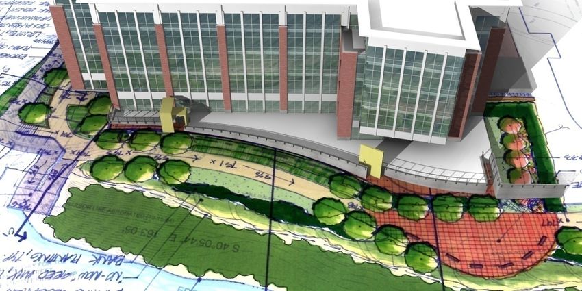
2.3 Building Envelope Architecture
Quantum III will reflect the existing mood in South Side works with an envelope that
emphasizes mass through brick façade while providing transparency through aluminum and glass
curtain walls. The building is set atop a solid concrete retaining wall, and the large yellow
colored mass in the forefront of the renderings is a “branding wall” featuring a larger than life
American Eagle Outfitters logo. Due to cost issues, the branding wall has since been removed
from the project.
Figure 3 – North Perspective with Branding Wall
Page 9 of 95Sam Jannotti American Eagle Outfitters
Quantum III
Pittsburgh, Pennsylvania
Vertical columns of façade brick backed by an airspace and 6” to 8” light gauge steel studs
segment and add mass to a façade dominated by aluminum and glass on the south elevation. The
north elevation includes this envelope but presents more brick with frequent large bay windows.
Riverfront terrace, with the featured “Branding Wall” lines the north elevation as well. The east
and west elevations are progressively clad with increasing amounts of brick façade, and the west
elevation features the service entrances. Facades are all tied together with composite aluminum
panel walls and a similar cornice.
The roofing system consists of fully adhered EPDM single ply membrane on rigid
insulation; backed with 3”, 20 gauge, galvanized steel roof deck throughout. The deck has at
least 3 continuous spans, and the rigid insulation is added to allow a ¼” per foot slope to drain
water while providing an R-value of 30. The membrane is wrapped around the inside and top of
the parapet to prevent leakage throughout the structure and wall systems.
2.4 Building Plan Architecture
American Eagle Outfitters South Side Works features an open plan featuring only those
partitions required in the core of the building: where elevators, stairs, bathrooms, storage, and
lateral resisting frames are present. The remainder of the plan is dotted with steel columns.
2.5 Zoning
B-2 new construction classified as B (business) in Pittsburgh County, Pennsylvania.
2.6 Structural Systems
The structural system for American Eagle Quantum III is primarily composed of wide-
flange steel columns and composite beams. The typical floor is 3” composite light weight
reinforced topping slab on 2” 20 gauge steel deck. Girders are typically W24x55 with W18x35
infill beams spaced at 10’ on center. The roof is constructed of W16’s with W12 infill beams
with a portion of composite slab to support the mechanical units. A windscreen surrounds the
mechanical equipment to counteract wind forces and hide it from sight of pedestrians below.
Connections are mainly simple shear connections. Columns are typically W10’s and W12’s
placed on a 30’x30’ grid.
Five vertical trusses are arranged throughout the building core and exterior. Three of the
five trusses are forms of a Chevron truss, with one X-braced frame and the last being a single
strut truss. Only one truss is on the exterior and is an excellent display of structure—a curtain
wall provides a view of it from the exterior of the building. The remaining four trusses are
interior and border stairs, elevators, or mechanical shafts. One of the interior trusses is eccentric
to avoid a conflict with stair access doors on the easternmost corner of the building.
Page 10 of 95Sam Jannotti American Eagle Outfitters
Quantum III
Pittsburgh, Pennsylvania
2.7 Mechanical Systems
QIII has two 35,000 pound rooftop air handling units providing a total 120,000 CFM. Heat
recovery wheels are installed and operate at 64% efficiency for cooling and 77% efficiency for
heating. The system is designed to use 36,000 CFM, or 30%, outside air. The boiler room is
located on the fifth floor, simplifying HVAC system layout by placing the units and boiler room
close vertically and horizontally. Hot water is supplied via two pumps operating at 66%
efficiency, pumping 250 gpm. There are typically two VAV boxes per floor, regulating air flow
vertically throughout the building.
2.8 Construction and Management
The delivery method is design-bid-build, with The Soffer Organization managing and
developing the land. American Eagle Outfitters Quantum III went out to bid December 2006,
and bids were selected based on economy, constructability, and quality. Groundbreaking
occurred in May 2007 and the building envelope and core construction is scheduled to be
completed in October 2008.
The contractor is responsible for the demolition of existing steel mill foundations,
estimated at +/- 40’ thick, with their location to be field verified. The majority of the site is
covered by the proposed building, with roads on two sides and the Monongahela River on
another—construction will therefore be tight. Storage of materials and the construction process
will require thinking outside of the box to limit interference with Pittsburgh area traffic and
congestion.
2.9 Electrical Systems
American Eagle Outfitters Quantum III has 277/480 V incoming power in a 3 phase 4 wire
system including a 150 kVA transformer, two 277/480 V panelboards, and four 208/120 V
panelboards on the first floor. There is a separate panel for low voltage lighting as well. Floors 2
and 5 have four panels of each voltage while floors 3 and 4 have similar layouts, but only have
two 277/480 V panels. Finally, power is transferred between floors via 2000A vertical bus
systems.
2.10 Lighting Systems
Lighting fixtures will be provided only in stairs, emergency egress areas, and the receiving
and storage facilities. Four foot fluorescent fixtures will be pendant mounted in receiving and
storage, and fixtures are ceiling mounted in stair wells. Metal halide is provided for the terrace
area, building façade, and aesthetically mounted in trees. Fluorescent bulbs must have a
minimum of 80 color rendering index (CRI) while metal halide lamps must achieve a CRI of 70.
The curtain wall façade will provide natural light throughout the interior of Quantum III
while allowing for spectacular views of the Pittsburgh skyline and historical bridges. Building
tenants must supply all other lighting and electrical components to suit individual needs.
Page 11 of 95Sam Jannotti American Eagle Outfitters
Quantum III
Pittsburgh, Pennsylvania
2.11 Fire Protection
All exit passageways, storage rooms over 100 square feet, and elevator shafts are rated for
2 hours, while stairwells are rated for 1 hour. A smoke control system is proposed though not
required by code. The structural frame and other floor and roof construction require no specific
fire protection—therefore no special protection is provided.
Two fire pumps supply water to the two sprinkler zones, with sprinklers located 12’ on
center—spacing is lowered where NFPA has special wall spacing requirements. Also,
standpipes are located in each of the two stairwells of American Eagle Outfitters: Quantum III.
One stairwell is located on the exterior wall towards the east corner of the building, and the other
is an interior stairwell on the north half of QIII.
2.12 Transportation
There are three entrances/exits on the first floor with two exits on each floor above.
Loading and unloading areas are provided on the north sides of the building. The loading docks
are angled roughly 45 degrees to allow a semi trailer and trash collection to fit on the northeast
side of the site, given the tight edge clearance of the building on all sides. The northwest side
contains a separate entrance and overhead partitioned doors in each bay, resulting in six separate
loading areas.
Three elevators are provided. The first is a cargo elevator provided by the interior stair,
while the remaining two border the core bathrooms and mechanical shafts. These two elevators
are open to future tenant use.
2.13 Communications
Two way communication between the building tenants/operators and fire agencies is
provided with each individual tenant installing personal communication needs. Service and data
rooms are provided with their own VAV boxes on each floor and are aligned vertically for easy
installation of multiple floor systems.
Page 12 of 95Sam Jannotti American Eagle Outfitters
Quantum III
Pittsburgh, Pennsylvania
2.14 Project Team
Owner: American Eagle Outfitters
- http://www.ae.com/web/index.jsp
Architect: The Design Alliance Architects
- http://www.tda-architects.com/
Construction Manager/Developer: The Soffer Organization
- http://www.sofferorganization.com/
Structural Engineer: Atlantic Engineering Services
- http://www.aespj.com/index.html
MEP Engineer: Tower Engineering
- http://www.tei-usa.com/
Civil: The Gateway Engineers, Inc.
- http://www.gatewayengineers.com/
Landscape: Environmental Planning and Design
Page 13 of 95Sam Jannotti American Eagle Outfitters
Quantum III
Pittsburgh, Pennsylvania
3. Structural Depth
3.1 Existing Structural Systems
3.1.1 Geotechnical and Foundation Concerns
The foundation of Quantum III will be constructed on abandoned steel industry facility
foundations with fills consisting of silty sand, cinder and slag. With the unpredictability of the
subgrade to the deeper bedrock, and the Monongahela River directly adjacent to the building,
shallow foundations cannot be used. The fill located deeper in the subgrade has a higher bearing
capacity than the aforementioned soils. Therefore, Geo-Mechanics Inc. insisted on 16” diameter
auger cast piles with an ultimate load capacity of 300 kips, and design load capacity of 120 kips.
Bedrock is located roughly 85 feet below the surface. With the water table resting at 730 ft
above sea level—slab on grade is proposed to be at 753’.
Since the building includes no plans for a basement, slab on grade connects with pile caps
and grade beams to make up the foundation of QIII. Grade beams line the exterior of the
building and connect pile caps where lateral frames are located. Interior gravity columns
typically have four piles with a single, separate pile cap, while columns on the exterior wall tie in
with grade beams and three- to four-pile configurations. Foundations are 3000 psi concrete with
5000 psi, 16” end bearing 60 ton auger-cast piles. Reinforced concrete grade beams aid in
counteracting lateral load uplift underneath the six vertical trusses as well as provide stability
around the perimeter of American Eagle Outfitters Quantum III. Foundation stability is a
pressing issue given the Monongahela River is but 45’ away.
Figure 4 – Ongoing QIII Construction by Monongahela River
Page 14 of 95Sam Jannotti American Eagle Outfitters
Quantum III
Pittsburgh, Pennsylvania
3.1.2 Floor Framing
Quantum III is designed for flexibility to allow individual tenants to lay out each floor as
they please. It utilizes 30’ by 30’ bays with a two ‘cores’ containing elevators, stairs, mechanical
openings and bathrooms. Since the extent of the work of the firms stated (Atlantic Engineering
Services, The Design Alliance Architects, etc.) was core and shell—the exact placement of
partitions is not addressed in the architectural plans as seen in Figure 5 – Typical Architectural
Floor Plan.
Figure 5 – Typical Architectural Floor Plan
Figure 6 – Typical Floor System Construction
Page 15 of 95Sam Jannotti American Eagle Outfitters
Quantum III
Pittsburgh, Pennsylvania
As you can see from the architectural plan, partition placement is not even considered in
this stage of the building development. To expand upon the structural system, typical bays for
the second through fifth floors are shown below in Figure 7.
All floor framing and steel deck is
composite. A lightweight concrete slab on 3”
galvanized steel deck was incorporated. Shear
studs are 4” long and ¾” diameter in 2.5”
lightweight concrete topping. The total slab and
deck thickness is 5.5”. Typical roof framing
consists of 3” metal roof deck, except the
mechanical unit area. 2” deck with 3” lightweight
concrete provides added support and dampens
mechanical vibrations here. Typical girders are
W24x55 with 28 studs. Infill beams are W18x35’s
spaced at 10’ center to center with 16 studs. Refer
to Figure 7 and Figure 8 for the floor framing
layout. American Eagle Outfitters Quantum III
has two bays to the north of the building cores as Figure 7 – Typical Bay
discussed earlier, and one set of bays to the south
as seen in Figure 8 – Typical Floor Framing.
Figure 8 – Typical Floor Framing
Page 16 of 95Sam Jannotti American Eagle Outfitters
Quantum III
Pittsburgh, Pennsylvania
3.1.3 Gravity System Columns
Typical columns in AEO: QIII consist of W10’s and W12’s. Splices are typically located
four feet above the top of slab. The fifth floor contains additional columns bearing on transfer
beams to support davit pedestals. Columns are placed on a 30’ by 30’ grid typically.
3.1.4 Lateral Load Resisting Elements
As stated earlier there are five vertical trusses arranged throughout the shell and core of
American Eagle Outfitters Quantum III. As shown in Figure 9, their placement was based on
resisting interference with the open plan. Also, on the next page are elevations of the vertical
trusses in Figure 10 and Figure 12.
Figure 9 – Vertical Truss Locations
Page 17 of 95Sam Jannotti American Eagle Outfitters
Quantum III
Pittsburgh, Pennsylvania
Figure 10 – Vertical Trusses A, B and C (VT-A, B, C)
Vertical truss (VT) A is a single strut truss, VT-B is an X-braced frame, and VT-C is a
Chevron truss. VT-A contains an eccentricity to avoid an architectural conflict with stair access
doors. All three of the above trusses are located on the interior of the building around stairs,
elevators, or mechanical shafts. Braces are HSS7x7’s with lateral frame columns ranging from
W14x82’s to W14x193’s. A standard inverted V-truss brace connection is detailed below.
Figure 11 – Brace Connection Detail
Page 18 of 95Sam Jannotti American Eagle Outfitters
Quantum III
Pittsburgh, Pennsylvania
Figure 12 – Vertical Trusses D and E (VT-D, E)
As shown above, VT-D and E are inverted V-trusses. VT-E is the only truss situated on an
exterior wall of the building as described earlier.
Page 19 of 95Sam Jannotti American Eagle Outfitters
Quantum III
Pittsburgh, Pennsylvania
3.1.5 3‐D Model Images
Figure 13 – 3D View from West Building Corner
Figure 14 – 3D View from East Building Corner
Page 20 of 95Sam Jannotti American Eagle Outfitters
Quantum III
Pittsburgh, Pennsylvania
3.2 Codes and Material Properties
3.2.1 Codes and Referenced Standards
American Eagle Outfitters Quantum III uses the 2003 International Building Code (IBC)
as amended by the City of Pittsburgh Building Department. The 2003 IBC references ASCE 7 –
02 and ACI 318-02. All analysis and design was performed by Atlantic Engineering Services
using Allowable Stress Design (ASD) as opposed to Load and Resistance Factor Design
(LRFD), which is used throughout this technical report. These design methods are prescribed in
the AISC Steel Construction Manual, 13th edition, as used for this report.
Codes used for this analysis are IBC 2006 without any Pittsburgh amendments, ASCE 7 –
05 and ACI 318 – 05. Also, California State amendments and Oakland City amendments were
analyzed. Upon inspection no amendments directly affected the following analysis.
3.2.2 Material Properties
Concrete
Foundations 3000 psi
Terrace Walls 4000 psi
Interior Slabs 4000 psi
Exterior Slabs 4000 psi
Site Access Canopy Walls 5000 psi
Auger Pile Grout 5000 psi
Reinforcing Steel (Yld) 60 ksi
Headed Concrete Anchors (Yld) ASTM A108 Grades 1015-1020 60 ksi
Steel
Structural Steel
W Shapes ASTM A992 50 ksi
M, S, HP Shapes ASTM A572 Grade 50 50 ksi
Channels ASTM A572 Grade 50 50 ksi
Steel Tubes (HSS Shapes) ASTM A500 Grade B 46 ksi
Steel Pipes (Round HSS) ASTM A500 Grade B 42 ksi
Angles ASTM A36 36 ksi
Plates ASTM A36 36 ksi
Page 21 of 95Sam Jannotti American Eagle Outfitters
Quantum III
Pittsburgh, Pennsylvania
Galvanized Structural Steel
Structural Shapes and Rods ASTM A123
Zinc Coating, Strength of base
Bolts, Fasteners, and Hardware ASTM A153
Zinc coating, Strength of base
Metal Decking (Yield Strength) 33 ksi
Light Gage Studs, 12-16 Gage ASTM A653 Grade D 50 ksi
Light Gage Studs, 18-20 Gage ASTM A653 Grade A 33 ksi
Masonry
Mortar (Prism Strength) ASTM C270 F’m = 2500 psi
Grout ASTM C476 F’c = 3000 psi
Masonry (Prism Strength, 28-day) F’m = 1500 psi
3.3 Existing System Loads and Criteria
3.3.1 Load Cases and Combinations
Below are the load cases considered for Quantum III. Wind and seismic loads were
applied in multiple directions to determine the most severe combination. Snow loads were not
included in this analysis.
1.4(D)
1.2(D) + 1.6(L) + 0.5(Lr)
1.2(D) + 1.6(Lr) + (0.5L or 0.8W)
1.2(D) + 1.6(W) + 0.5(L) + 0.5(Lr)
1.2(D) + 1.0E + 0.5L
0.9(D) + (1.6W or 1.0E)
Page 22 of 95Sam Jannotti American Eagle Outfitters
Quantum III
Pittsburgh, Pennsylvania
3.3.2 Dead Loads
Unit weights and dead loads are taken from the AISC Steel Manual, 13th Edition. Wall
weights are supplied in the structural documents of American Eagle Outfitters: Quantum III.
Mechanical unit surface loads described in Figure 16 below are based on an AES design method:
distribute two-thirds of the unit weight over one-third the area and the reciprocal distribution of
the remaining weight. Of the four
distributed loads, the most severe
combination is applied to the structure.
This assumes most of weight is focused in
one section of the mechanical unit and
insures QIII is designed for the worst case
scenario. The ‘opening’ refers to the
opening for mechanical ducts. Finally, all
supporting calculations are available in
Appendix A.
Figure 15 – Dead Loads
Figure 16 – Mechanical Unit Surface Loads
3.3.3 Wall Loads
Curtain Walls………………………………...20 psf (specified in AEO:QIII General Notes)
8” CMU, grout/rein. 24” cc……………...…..51 psf
Partitions……………………………………..20 psf (specified in AEO:QIII General Notes)
Page 23 of 95Sam Jannotti American Eagle Outfitters
Quantum III
Pittsburgh, Pennsylvania
3.3.4 Live Loads
The typical bay for the roof has the same dimensions as that for the typical floor, so all
reduced live loads are based on the bays and spacing outlined in 3.1.2 Floor Framing.
Location Load (psf) Description
At = 10' x 30' = 300 ft2
∴ R1 = 1.2 - 0.001At = 1.2 - 0.001 * (300 ft2) = 0.9
20
Roof F = 0, the roof pitch is small enough to be negligible
18
∴ R2 = 1
∴ Lr = R1 * R2 * L = 0.9 x 1.0 * 20 = 18 psf
Offices require only 50 psf but since the building is designed
to be flexible for tenant fit out, the location of corridors
is not currently known, and the conservative corridor load
is applied over the entire plan
KLL = 4 : Interior Beams
At, beam = 300 ft2
450
At, girder = 15 ft x 30 ft =
ft2
Offices and
80
corridors 15
above the
54.6
48.3
L= (
Lo x 0.25 + (KLL x At)0.5 ) =
first floor
15
= (
80 x 0.25 + (4 x 300 ft2)0.5 ) = 54.6 psf
15
L= (
Lo x 0.25 + (KLL x At)0.5 ) =
15
= (
80 x 0.25 + (4 x 450 ft2)0.5 ) = 48.3 psf
Lobbi
es and first Irreducible per ASCE 7-05 Section 4.8.2
100
floor
corridors
Stairs 100
Page 24 of 95Sam Jannotti American Eagle Outfitters
Quantum III
Pittsburgh, Pennsylvania
3.3.5 Existing Building Wind Criteria
A comparison of wind pressures acting on the main wind force resisting system in
Pittsburgh, Pennsylvania is described below. Since the seismic forces in southwestern PA are
minimal, wind shears control the design of the lateral force resisting systems. The wind criteria
determined for Oakland, California are presented in Appendix B.1.
Assumptions
Building Height (h) 72.33’
Basic Wind Speed (3 second gust) 90
Exposure Category C
Enclosure Classification Enclosed
Building Category II
Importance Factor 1.0
Internal Pressure Coefficient ±0.18
Wind Directionality Factor (Kzt) 0.85
Topographic Factor (Kd) 1.0
Gust Effect Factor (G) 0.84, 0.89
3.3.6 Existing Building Seismic Criteria
Atlantic Engineering Services determined a Seismic Design Category of A for American
Eagle Outfitters Quantum III, requiring equivalent lateral forces, Fx, to equal one percent of the
total dead load assigned to or located at Level x. They arrived at this conclusion by obtaining
different mapped spectral response accelerations of SS = 0.131 g and S1 = 0.058 g. This carried
throughout the entire seismic calculation, resulting in SDS = 0.1 g and SD1 = 0.06 g—values small
enough to qualify for a seismic design category of A. This can be attributed to differing latitude
and longitude measurements. In this analysis, Google Earth was used to compute the latitude
and longitude of QIII, which resulted in a seismic design category of B. The vertical truss
analysis uses category B.
Occupancy Category II
Seismic Use Group II
Importance Factor (I) 1.0
Latitude and Longitude 40°25’32.71” N 79°
57’50.93” W
Mapped Spectral Response Accelerations
Ss = 0.125 g
S1 = 0.049 g
Site Class D
Site Class Factors
Fa = 1.60
Fv = 2.40
Page 25 of 95Sam Jannotti American Eagle Outfitters
Quantum III
Pittsburgh, Pennsylvania
SMS 0.20
SM1 0.1176
SDS 0.133
SD1 0.0784
Seismic Design Category B
Braced Frames are a “Steel System Not Specifically Detailed for Seismic Resistance”
Response Modification Factor (R) 3.0
Over-strength Factor (Wo) 3.0
Deflection Amplification Factor (Cd) 3.0
Seismic Response Coefficient (Ct) 0.02
Period Coefficient 0.75
Seismic Coefficient (Cs) 0.0284
Building Period (T) 0.921
k 1.211
3.4 Basis for Structural Redesign
Evidence of American Eagle Outfitters current expansion is apparent in Pittsburgh,
Pennsylvania. In the past few years, AEO has had two corporate expansions, of which Quantum
III is the last installment. Michael Sandretto did a study on Quantum II just last year in AE
481W and 482. The fast turnout of additional corporate office buildings lend to the belief that
more Quantum structures are on their way.
As a response to the rapid growth, American Eagle Outfitters could propose expanding
with a corporate headquarters on the west coast. To save on design costs, a similar building to
Quantum III could be constructed in Oakland, California. The new west coast headquarters must
consider the large market the office space must tailor to—so two typical floor layouts will be
added in QIII’s elevation.
(Note this in no way reflects the actual plans of American Eagle Outfitters and is proposed
for the sole purpose of this structural depth.)
3.4.1 Gravity System
The floor plan on the new American Eagle Outfitters: Quantum building will also reflect
the need for flexibility. Therefore, the dead and live loads applied on QIII will remain
unchanged.
Page 26 of 95Sam Jannotti American Eagle Outfitters
Quantum III
Pittsburgh, Pennsylvania
3.4.2 Lateral Force Resisting Elements
Given the seismic design considerations of California, a complete redesign of the lateral
systems must be carried out. The original QIII design was in Pittsburgh, Pennsylvania; and was
controlled by wind. Due to the large seismic induced forces present in California, lateral systems
must be scaled up significantly. Column, brace, and girder sections must all increase as well.
Special care will be taken in designing the details for the new Quantum building to ensure safety
of the occupants in the event of an earthquake.
Moving the building to a new location presents many new factors when considering a
lateral system redesign. The possibility of requiring additional vertical trusses will be met
considering the effect of each truss on the existing open floor plan. Also, the higher cooling
loads necessary in Oakland can result in the rooftop mechanical unit loads being increased. As a
result, seismic acceleration and equivalent loads can grow. As with any engineering task,
construction economics will be a considerable factor in the redesign of the lateral systems. The
redesign of the lateral force resisting system will take account of all these factors throughout the
following pages.
3.4.3 Design Goals and Scope
Due to the inherent complexities of moving a building design to a new site, the goal is to
reach an adequate preliminary design for the lateral force resisting system. In this respect,
building geometry, redundancy, and the development of plastic hinges throughout the vertical
trusses will be taken into account. The lateral force resisting systems will be designed based on
strength. Additionally, a preliminary drift evaluation under both wind and seismic loads will be
determined to solidify the controlling case.
Overall, the scope of this study is to gain an understanding of design methods used in the
architectural engineering field. With experience in East Coast design methods, the move to West
Coast provides the daunting task of designing lateral systems to resist earthquake induced loads.
The three technical reports completed last fall shrink in comparison to this study on a number of
issues. With that said, the following pages outline the precautions taken to design a building to
resist and withstand earthquake induced forces, not only to allow the safety of building
occupants, but those people inhabiting and travelling through neighboring sites.
Page 27 of 95Sam Jannotti American Eagle Outfitters
Quantum III
Pittsburgh, Pennsylvania
3.5 Proposed Gravity System
3.5.1 Gravity Framing
As stated earlier, dead and live loads remain unaltered from the previous Quantum III
design. The result is a gravity system not unlike the existing structural sandwich. RAM
Structural System was used to obtain the preliminary gravity beams, girders, and columns.
Two typical floors, each at 13’-8” were inserted above the fourth floor. The result was the
minor increasing of lower level column sections. Also, the sections that were designated as part
of the frame system were altered to be gravity members alone. This provided the minimal
allowable design for girders and columns entering into the lateral force resisting system,
satisfying the requirement for all frame girders to withstand gravity forces neglecting the truss
braces. Shown below is a simple comparison of existing versus new gravity members
throughout QIII’s structure.
Figure 17 – Gravity Member Comparison
3.5.2 Gravity Frame Detailing
At this point, the level of detail in the gravity system is sufficient to conduct a
preliminary lateral force resisting system design. To continue with the depth, a certain number
of details were neglected because of their minimal impact on the lateral frame design:
1) Torsion of beams and girders eccentrically supporting shell elements
2) Infill beams around floor openings
3) Reinforced exterior masonry walls at the service entrance on the first floor
Page 28 of 95Sam Jannotti American Eagle Outfitters
Quantum III
Pittsburgh, Pennsylvania
3.6 Proposed Lateral Frame Design
3.6.1 New Wind Criteria
Oakland, California has different wind criteria which are outlined below. The actual wind
force calculations were completed using an Excel spreadsheet adapted from Technical Report 1.
They are available in Appendix B.1.
Assumptions
Building Height (h) 96.64’ to Roof T.O.S.
Basic Wind Speed (3 second gust) 85
Exposure Category C
Enclosure Classification Enclosed
Building Category II
Importance Factor 1.0
Internal Pressure Coefficient ±0.18
Wind Directionality Factor (Kzt) 0.85
Topographic Factor (Kd) 1.0
Gust Effect Factor (G) 0.85, 0.88
3.6.2 Wind Design Methodology
Wind pressures were determined using Microsoft Excel (1), and then plotted on a 2-D
scale model of the building in AutoCAD. Using the inquiry function, the area of building
enclosure was determined and multiplied to find equivalent forces (2). The wind forces were
lumped at each floor level, and overturning moment and base shear were calculated in Excel
based on each floor’s height (3). At this point, lumped wind shears were applied on the
diaphragm of an ETABS building model (4). Story drifts were then printed from ETABS, and
inserted into another Excel spreadsheet that checked they meet serviceability requirements (5).
The methodology is outlined below, and the applicable graphs and output for each step of the
process is available in Appendix B.1.
1 2 3
4 5
Figure 18 – Wind Analysis Methodology
Page 29 of 95Sam Jannotti American Eagle Outfitters
Quantum III
Pittsburgh, Pennsylvania
3.6.3 Wind Story Shears and Overturning Moments
A comparison of North-South and East-West wind was performed to determine which
would control story drift. Wind pressures are not assumed to control the strength of lateral force
resisting braced frames. Therefore, shears are found to analyze the wind story drift limitation of
H/400. Below are the equivalent story shears lumped at each floor level.
Figure 19 – North-South Wind Shears and Overturning Moments
Page 30 of 95Sam Jannotti American Eagle Outfitters
Quantum III
Pittsburgh, Pennsylvania
Figure 20 – East West Wind Shears and Overturning Moments
As you can see in Figure 19, North-South wind forces are greater, and will control the
wind drift check of American Eagle Outfitters: Quantum III. A conservative estimate of the
building weight resulted in a factor of over 60 against overturning. This is due to the large
volume of the building in comparison to the surface area wind can act on. The overturning
calculation is available in Appendix B.2.
Page 31 of 95Sam Jannotti American Eagle Outfitters
Quantum III
Pittsburgh, Pennsylvania
3.6.4 Wind Induced Story Drift
The story drift of Quantum III as a result of wind induced forces was minimal at most.
Since wind was not assumed to control story drift or strength design of the vertical trusses, they
were designed using seismic loads. After a satisfactory preliminary design was achieved in
ETABS, wind forces were applied on the model and drift was calculated. The minimum allowed
story drift was equivalent to 0.40625 inches at the first floor. With large seismic force resisting
vertical trusses, wind induced drift was limited to less than 1/1000th of an inch for a single story.
This reinforces the assumption that seismic forces not only control the design of the lateral
system but dominate it. The study of wind forces on AEO: QIII did not progress beyond this
stage to allow ample time to analyze the complexities of earthquake induced forces.
3.6.5 New Seismic Criteria
As shown below, the seismic coefficients for California vary greatly from that of
Pennsylvania. In order to meet code requirements for seismic design category E, the AISC
Seismic Design Manual was used. Since American Eagle Outfitters: Quantum III contains both
eccentrically braced frames and concentric braced frames, the conservative Response
Modification Factor, Over-strength Factor, and Deflection Amplification factors were used.
These values were that for special steel concentric braced frames. Supporting calculations are in
Appendix B.3.
Occupancy Category II
Seismic Use Group II
Importance Factor (I) 1.0
Location 12th St., Oakland, California
Mapped Spectral Response Accelerations
Ss = 1.522 g
S1 = 0.6 g
Site Class D
Site Class Factors
Fa = 1. 0
Fv = 1.5
SMS 1.522
SM1 0.9
SDS 1.015
SD1 0.6
Seismic Design Category E
Braced Frames are “Special Steel Concentric Braced Frames”
Response Modification Factor (R) 6
Over-strength Factor (Wo) 2.0
Deflection Amplification Factor (Cd) 5.0
Page 32 of 95Sam Jannotti American Eagle Outfitters
Quantum III
Pittsburgh, Pennsylvania
Seismic Response Coefficient (Ct) 0.02
Period Coefficient 0.75
Seismic Coefficient (Cs) 0.1054
Building Period (T) 0.949
3.6.6 Additional Lateral Frames
From the start of the lateral system redesign it was understood that the five frames present
throughout American Eagle Outfitters: Quantum III will not be sufficient for seismic forces. To
provide for redundancy and achieve an adequate preliminary design, a number of locations for
additional braced frames were investigated. Existing vertical trusses are designated with a VT
and potential new trusses are designated with an NT. See Figure 21 below.
Figure 21 – Existing and Potential New Vertical Truss Locations
Most direct shear will be taken by the most rigid frames, so VT and NT-C would dominate
the design in the y direction. VT-D, E, and NT-A are all 30’ span trusses and will provide
excellent shear resistance and redundancy in the x direction. NT-B, D, and E all span 15’, and
are therefore less efficient to resist story shears. However, their placement on the building shell
maximizes their ability to resist torsional shears. Because the lateral force resisting systems are
placed so asymmetrically, there exists the possibility of torsional irregularities. Not only could
this increase the apparent seismic forces on the building through the redundancy factor and
torsional shears, but can cause equivalent lateral force analysis to be not permitted.
Page 33 of 95Sam Jannotti American Eagle Outfitters
Quantum III
Pittsburgh, Pennsylvania
3.6.6.1 Vertical Truss Elevations
As shown to the right, the proposed trusses B, D and E are slimmer, reducing their
efficiency in resisting story shears. The X-bracing scheme
also is inefficient in the number of connections it requires.
On a per story basis, an X-braced frame requires five
connections to be detailed whereas an inverted V-truss such
as NT-A and C require only three. In a seismic controlled
region such as Oakland, California; the detailing would
vastly increase the building cost.
To combat the amount of detailing required NT-B, D,
and E should be changed to inverted V-trusses beyond this
preliminary design. In addition, the elevations below
demonstrate the need for foundation detailing at the base of
NT-B and D. They appear to be “floating”. Be assured this
is not the case; the slab on grade is directly below the end of
the truss outlined in blue. Therefore, the walls shown below
are a combination of structural and retaining walls. Special
reinforcing details are required to insure shear and axial
forces are transferred to foundations and piles. (Note: Image
below is of original QIII elevation and is used to
demonstrate the foundation requirements below trusses NT-
B and D.) Figure 22 – Proposed Truss Elevations
Figure 23 – West Elevation and NT-B and D
Page 34 of 95Sam Jannotti American Eagle Outfitters
Quantum III
Pittsburgh, Pennsylvania
3.6.7 Seismic Design
A number of differing methodologies were employed in determining frame location and
sizes for QIII. To get to the current preliminary design, the author went through over five
possible designs of the lateral system, and with each iteration, discovering more efficient design
methods. All methods employed RAM Structural System for story weights and SCBF beam
gravity designs. Excel was used to determine equivalent seismic story forces. These forces were
then compared to ETABS calculated results. Each method diverged in its approach to design the
lateral system after this point. These anomalies in approach are outlined in Sections 3.6.7.2 and
3.6.7.3.
3.6.7.1 Seismic Story Shears
Utilizing story weights obtained from an updated RAM Structural System Model,
equivalent seismic story forces and shears were found. By applying the respective building
period and seismic coefficient (Cs), the forces, story shears, and overturning moments shown
below were obtained. Also, the Excel and hand calculations were compared to ETABS model
results shown in Figure 25.
Figure 24 – Seismic Base Shears
Page 35 of 95Sam Jannotti American Eagle Outfitters
Quantum III
Pittsburgh, Pennsylvania
Figure 25 – Seismic Base Shear Comparison
3.6.7.2 Design A
Elevation and Framing
The layout used for the first design included all existing trusses as well as NT-B, C, and D.
To place NT-C, columns moved less than 6’ to be flush with the mechanical space opening
shown in Figure 21. Beams that framed into this column were slightly elongated or shortened
and had minimal effect on the beam design or structural sandwich.
Methodology
The first design involved trial and error through sizing and resizing frame members in
ETABS. As expected, there are many faults with this approach. First, the systematic increasing
of member sections to resist lateral loads proved to be fundamentally flawed. After adding NT-B
and D, all y axis frame sections were simultaneously increased. In effect, by increasing the
column sections of VT and NT-C, their stiffness increased as well. Therefore more seismic
shear was distributed to this frame. This resulted in ever-increasing section sizes, never
producing an adequate framing layout.
At this point in study, it was found that taking a counter-intuitive approach to lateral
design was necessary. By downsizing the most rigid braced frame, more story shear is filtered to,
in this case, NT-B and D. When all members finally passed the preliminary ETABS design,
most columns for exterior wall trusses were a staggering W14x730. Conversely, interior truss
column sections were W14x370 or smaller. When lateral frame dead and live loads were
applied, these interior column sections were too small for combined loading. At this point, this
design method was proved inadequate and other means were pursued.
Page 36 of 95Sam Jannotti American Eagle Outfitters
Quantum III
Pittsburgh, Pennsylvania
3.6.7.3 Design B
This design on American Eagle Outfitters: Quantum III was the most in depth analysis
performed for the structural depth. It utilized Excel spreadsheets, ETAB’s, and RAM Structural
System to get preliminary frame member sizes based on criteria outlined in Methodology.
Elevation and Framing
Due to the high relative stiffness of frames VT and NT-C and the apparent gravity loads,
these trusses proved inadequate for preliminary design. If sections increased, more shear force
would cause them to fail; decreased sections meant failure under gravity loads and minor
combination loading. Therefore, both of these were removed. The remaining frames in Design
B are shown below.
Figure 26 – Design B Frame Locations
V-trusses are researched as an alternative for X-braced frames NT-
B and D due to the increased number of connections required. At 15’
long, the member sizes and number of connections required for X-braces
create a massive frame that is not efficient or economic. Inverted V-
trusses interrupt vertical load paths of the braces and therefore require
Figure 27 – Design B
more shear strength in beams. The author believed this to be an
VT-B and D Elevation
adequate sacrifice to avoid more connection details. The elevation for
NT-B and D is at right.
Page 37 of 95Sam Jannotti American Eagle Outfitters
Quantum III
Pittsburgh, Pennsylvania
Methodology
Design B utilized the full design process shown below to achieve a preliminary lateral
framing design for American Eagle Outfitters: Quantum III. The flowchart has step by step
descriptions and Appendix B.3 has each spreadsheet utilized in Design B. Had more time been
available, further analysis would be performed. Further considerations past what is covered in
this methodology is outlined in 3.6.7.4.
1
3
2 6
4 5
7
8 9 10 11
12 13 14
Figure 28 – Design B Methodology
As outlined previously, RAM Structural System was used to find story weights and add
them into Excel (1). Story shears, calculated in Excel, were compared to those found in ETABS
(2). The seismic shear forces, determined from Excel, were then divided by the number of
trusses acting in each orthogonal direction. For frames running in the x-direction in Figure 26,
total seismic story shear was divided by three. This assumes each frame is equally rigid and
neglects torsion. For frames running in the y-direction, the seismic story shear was divided by
two. NT-B and D are significantly less rigid and therefore provide less resistance to seismic
shears as VT-A (3).
Using work-energy method, preliminary column sizes were found based on allowable drift.
An Excel spreadsheet was developed to analyze virtual loads acting on each vertical truss, and
calculate their expected story drift (4). The members optimal, cross sectional areas were then
determined based on their allowable seismic drift and equivalent lateral forces through a
correction factor (5-7). An example spreadsheet for this procedure is available in Appendix B.3.
The required frame sections were then put into an ETAB’s model, and torsional effects
were taken into consideration. Utilizing strength design, all members were sized against the 50
load cases ETABS considered (8). Frame forces were then input to Excel, which would locate
the maximum shear and moment on beams (10). Frame designs were inserted to another,
Page 38 of 95You can also read