Installer's Guide to Troubleshooting an Enphase System
←
→
Page content transcription
If your browser does not render page correctly, please read the page content below
Troubleshooting an Enphase System Installer’s Guide to Troubleshooting an Enphase System 1 2014 Enphase Energy Inc. August 2014
Troubleshooting an Enphase System
Contact Information
Enphase Energy Inc.
1420 N. McDowell Blvd.
Petaluma, CA 94954
http://www.enphase.com
info@enphaseenergy.com
support@enphaseenergy.com
FCC Compliance
This equipment has been tested and found to comply with the limits for a Class B digital device, pursuant
to part 15 of the FCC Rules. These limits are designed to provide reasonable protection against harmful
interference in a residential installation. This equipment generates, uses and can radiate radio frequency
energy and, if not installed and used in accordance with the instructions, may cause harmful interference
to radio communications. However, there is no guarantee that interference will not occur in a particular
installation. If this equipment does cause harmful interference to radio or television reception, which can
be determined by turning the equipment off and on, you are encouraged to try to correct the interference
by one or more of the following measures:
Reorient or relocate the receiving antenna.
Increase the separation between the equipment and the receiver.
Connect the equipment into an outlet on a circuit different from that to which the receiver is
connected.
Consult the dealer or an experienced radio/TV technician for help.
Changes or modifications not expressly approved by the party responsible for compliance may void the
user’s authority to operate the equipment.
Other Information
Product information is subject to change without notice. All trademarks are recognized as the property of
their respective owners.
User documentation is updated frequently; Check the Enphase website
(http://www.enphase.com/support) for the latest information.
For warranty text, refer to http://www.enphase.com/warranty.
For Enphase patent information, refer to http://enphase.com/company/patents/.
© 2014 Enphase Energy Inc. All rights reserved.
2 2014 Enphase Energy Inc. August 2014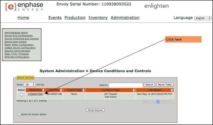
Troubleshooting an Enphase System
Table of Contents
Important Safety Information ......................................................................................................................... 5
Read this First .................................................................................................................................. 5
Product Labels ................................................................................................................................. 5
Safety and Advisory Symbols .......................................................................................................... 5
Safety Instructions ............................................................................................................................ 5
General Safety.............................................................................................................................................5
Microinverter Safety .....................................................................................................................................6
Engage Cable and Accessory Safety ..........................................................................................................7
Overview ....................................................................................................................................................... 8
Troubleshooting Topics ................................................................................................................................. 9
Envoy and Communications Issues ............................................................................................................ 11
Envoy Issues .................................................................................................................................. 11
A physical Ethernet connection is not practical at the site ......................................................................... 11
LCD is completely blank ............................................................................................................................ 12
LCD displays “Reset Clock” ....................................................................................................................... 12
LCD displays “Envoy Failure” .................................................................................................................... 12
LCD displays "Scanning Inhibited" ............................................................................................................ 12
Networking and Internet Issues ..................................................................................................... 13
Issue: Wireless Adapter Wi-Fi Problems ................................................................................................... 13
Issue: How Set Up Wi-Fi without Wi-Fi WPS ............................................................................................. 13
LCD shows a non-routable/self-assigned IP address AND shows “-Web” ................................................ 15
The Envoy is using a static IP and cannot get a web connection .............................................................. 17
LCD periodically shows “-Web” for minutes or hours at a time. ................................................................. 17
LCD shows a valid IP, but also shows “-Web” ........................................................................................... 17
The router or DSL modem at the site has only one Ethernet port .............................................................. 17
Internet service is not available on site ...................................................................................................... 18
Are my power line communication bridges working? ................................................................................. 19
Issue: Internet Traffic is Slower After Installing a Bridge ........................................................................... 19
Asoka PL9650....................................................................................................................................... 19
Asoka PL9660-Q1................................................................................................................................. 19
ReadyNet EN200 .................................................................................................................................. 19
Tenda P200 .......................................................................................................................................... 20
The Envoy cannot get a “+Web” even though all premises networking is intact ........................................ 20
Can I use a dial-up Internet connection with the Envoy? ........................................................................... 20
Power Line Communication Issues between the Envoy & Microinverters ..................................... 21
Microinverters are not detected, or, power line communication level is low or poor .................................. 22
How to identify an interfering load ............................................................................................................. 24
The Envoy is in a circuit on the primary load center, the solar circuits are on a downstream subpanel .... 24
Power line communications with a Line-side Tap (or Supply-Side, or PLC) Installation ............................ 25
Multiple Envoys and Filtering ..................................................................................................................... 25
Using a Transformer to Isolate Communication Domains ......................................................................... 25
Using an Aftermarket Filter to Isolate Communication Domains................................................................ 26
How to Get Training on Enphase Power Line Communication .................................................................. 26
3 2014 Enphase Energy Inc. August 2014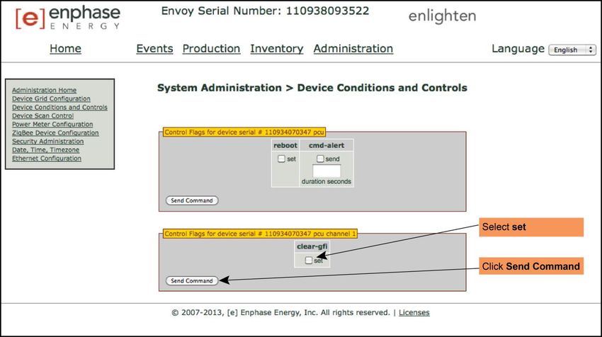
Troubleshooting an Enphase System
Microinverter and PV Module Issues .......................................................................................................... 27
Microinverter LEDs ......................................................................................................................... 27
Startup LED Operation .............................................................................................................................. 27
Post-Startup LED Indications..................................................................................................................... 27
The Microinverter LEDs are flashing red ................................................................................................... 28
The Microinverter LEDs are flashing orange ............................................................................................. 28
The Microinverter LEDs are not lit ............................................................................................................. 28
Power Production ........................................................................................................................... 28
The unit under review shows low production. ............................................................................................ 28
One unit shows 0W of production but adjacent units are productive ......................................................... 29
About Open-Circuit Voltage ....................................................................................................................... 30
Other Checks............................................................................................................................................. 30
The PV modules are dark and no production displays in Enlighten ........................................................... 31
Enlighten does not allow me to select the PV module ............................................................................... 31
View the PV module production history ..................................................................................................... 31
Run a report to view production history ..................................................................................................... 31
View module production history ................................................................................................................. 32
There is an event or alert message on the system .................................................................................... 32
Messages and Alerts ................................................................................................................................... 33
ACFOOR (AC Frequency Out of Range) ....................................................................................... 33
ACVOOR (AC Voltage Out of Range) ........................................................................................... 34
ACVOOR in an entire branch or multiple branches ................................................................................... 34
ACVOOR in only a few microinverters ....................................................................................................... 36
Critical Temperature ....................................................................................................................... 37
DC Resistance Low – Power Off ................................................................................................... 37
DC Too Low ................................................................................................................................... 39
DC Too High .................................................................................................................................. 40
Device Produced No Power ........................................................................................................... 40
Envoy not Reporting ....................................................................................................................... 40
Gateway Failure ............................................................................................................................. 40
GFI Tripped .................................................................................................................................... 41
Grid Gone ....................................................................................................................................... 42
Microinverter Failed to Report ........................................................................................................ 43
Over Temperature .......................................................................................................................... 43
Zigbee Device Failed to Report ..................................................................................................... 43
Zigbee USB Stick Removed .......................................................................................................... 43
Best Practices ............................................................................................................................................. 44
Installation sequence ..................................................................................................................... 44
Care of the solar array ................................................................................................................... 44
How do I clean the solar array? ................................................................................................................. 44
How do I maintain the solar array? ............................................................................................................ 44
Will a grid-tied solar array provide power during a power outage? ............................................................ 44
Will the array provide power during when it is snowing or hailing? ............................................................ 45
Can I add solar panels to the solar power system later? ........................................................................... 45
Other Questions? ...................................................................................................................................... 45
4 2014 Enphase Energy Inc. August 2014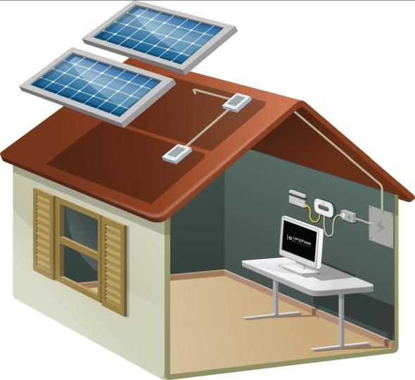
Troubleshooting an Enphase System
Important Safety Information
Read this First
This manual contains important instructions for installers to use during installation and maintenance of the Enphase®
Microinverter System™.
Product Labels
The following symbols appear on the product label and are described here:
WARNING: Hot surface.
DANGER: Risk of electrical shock.
Refer to product instructions.
Safety and Advisory Symbols
To reduce the risk of electric shock, and to ensure the safe installation and operation of the Enphase® Microinverter,
the following safety symbols appear throughout this document to indicate dangerous conditions and important safety
instructions.
DANGER! This indicates a hazardous situation, which if not avoided, will result in death or serious
injury.
WARNING! This indicates a situation where failure to follow instructions may be a safety hazard or
cause equipment malfunction. Use extreme caution and follow instructions carefully.
WARNING! This indicates a situation where failure to follow instructions may result in burn injury.
NOTE: This indicates information particularly important for optimal system operation. Follow
instructions closely.
Safety Instructions
General Safety
CAUTION: Before installing or using the Enphase Microinverter, read all instructions and
cautionary markings in the technical description, on the Enphase Microinverter System, and on the
photovoltaic (PV) equipment.
DANGER: Risk of electric shock. Do not use Enphase equipment in a manner not specified by the
manufacturer. Doing so may cause death or injury to persons, or damage to equipment.
DANGER: Risk of electric shock. Be aware that installation of this equipment includes risk of
electric shock. Do not install the AC junction box without first removing AC power from the Enphase
System.
DANGER: Risk of electric shock. The DC conductors of this photovoltaic system are ungrounded
and may be energized.
WARNING: Risk of electric shock. Always de-energize the AC branch circuit before servicing.
Never disconnect the DC connectors under load.
5 2014 Enphase Energy Inc. August 2014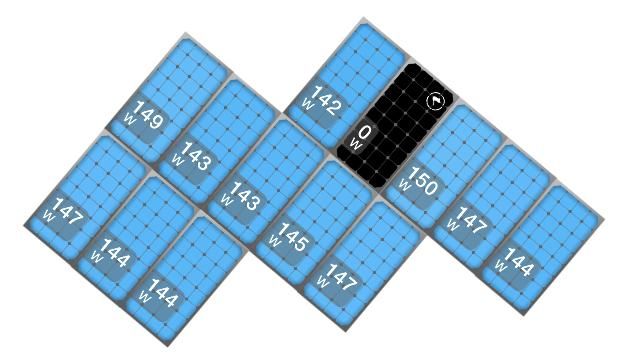
Troubleshooting an Enphase System
WARNING: Risk of electric shock. Risk of fire. Only use electrical system components approved for
wet locations.
WARNING: Risk of electric shock. Risk of fire. Only qualified personnel should troubleshoot, install,
or replace Enphase Microinverters or the Engage Cable and Accessories.
WARNING: Risk of electric shock. Risk of fire. Ensure that all AC and DC wiring is correct and that
none of the AC or DC wires are pinched or damaged. Ensure that all AC junction boxes are
properly closed.
WARNING: Risk of electric shock. Risk of fire. Do not exceed the maximum number of
microinverters in an AC branch circuit as listed in the manual. You must protect each microinverter
AC branch circuit with a 20A maximum breaker.
WARNING: Do not connect Enphase Microinverters to the grid or energize the AC circuit(s) until
you have completed all of the installation procedures and have received prior approval from the
electrical utility company.
NOTE: To ensure optimal reliability and to meet warranty requirements, the Enphase Microinverter
System must be installed according to the instructions in this manual.
NOTE: The AC and DC connectors on the cabling are rated as a disconnect only when used with
an Enphase Microinverter.
NOTE: Protection against lightning and resulting voltage surge must be in accordance with local
standards.
NOTE: Many PV modules have a central stiffening brace. In these cases, do not position the
connector and microinverter at the exact centre of the PV module. Instead, position the drop
connectors so that the connectors do not conflict with the braces.
NOTE: Completely install all microinverters and all system AC connections prior to installing the PV
modules.
Microinverter Safety
WARNING: Risk of Skin Burn. The body of the Enphase Microinverter is the heat sink. Under
normal operating conditions, the temperature is 15°C above ambient, but under extreme conditions
the microinverter can reach a temperature of 80°C. To reduce risk of burns, use caution when
working with microinverters.
WARNING: Risk of electric shock. Risk of fire. If the AC cable on the microinverter is damaged, do
not install the unit.
WARNING: Risk of electric shock. Risk of fire. Do not attempt to repair the Enphase Microinverter;
it contains no user-serviceable parts. If it fails, contact Enphase customer service to obtain an RMA
(return merchandise authorization) number and start the replacement process. Tampering with or
opening the Enphase Microinverter will void the warranty.
WARNING: Risk of Equipment Damage. The M215 and M250 may be paired only with 60-cell PV
modules.
WARNING: When pairing with M250 (M250-60-2LL-S22, S23, or S24) or M215 (M215-60-2LL-S22-
IG, S23-IG, or S24-IG), the PV module DC conductors must be labeled “PV Wire” or “PV Cable”.
WARNING: Risk of Equipment Damage. You must match the DC operating voltage range of the PV
module with the allowable input voltage range of the Enphase Microinverter.
WARNING: Risk of Equipment Damage. The maximum open circuit voltage of the PV module must
not exceed the specified maximum input DC voltage of the Enphase Microinverter.
WARNING: Risk of Equipment Damage. The microinverter must be installed under the module, out
of rain and sun. Do not mount the microinverter in a position that allows long-term exposure to
direct sunlight or in a vertical orientation that allows water to collect in the DC connector recess. Do
not install the microinverter black side up or vertically, with the DC connectors facing up.
WARNING: Be aware that only qualified personnel may connect the Enphase Microinverter to the
utility grid.
6 2014 Enphase Energy Inc. August 2014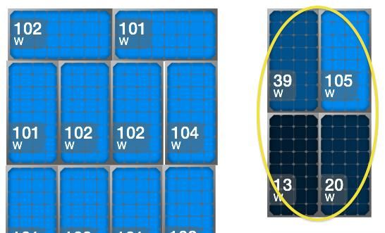
Troubleshooting an Enphase System
NOTE: The Enphase Microinverters has field-adjustable voltage and frequency trip points that may
need to be set, depending upon local requirements. Only an authorized installer with permission
and following the requirements of the local electrical authorities should make adjustments.
NOTE: The Enphase Microinverter works with single-phase or three-phase electrical service.
Engage Cable and Accessory Safety
DANGER: Risk of electric shock. The Engage Cable terminator cap must not be installed while
power is connected.
WARNING: Risk of electric shock. Risk of fire. When stripping the sheath from the Engage Cable,
make sure the conductors are not damaged. If the exposed wires are damaged, the system may
not function properly.
WARNING: Risk of electric shock. Risk of fire. Do not leave AC connectors on the Engage Cable
uncovered for an extended period. If you do not replace the microinverter immediately, you must
cover any unused connector with a sealing cap. Sealing caps may not be reused.
WARNING: Risk of electric shock. Risk of fire. Make sure protective sealing caps have been
installed on all unused AC connectors. Unused AC connectors are live when the system is
energized by the grid. Sealing caps may not be reused.
WARNING: Use the terminator only once. If you open the terminator following installation, the
latching mechanism is destroyed. Do not reuse the terminator. Do not circumvent or manipulate the
latching mechanism.
CAUTION: When installing the Engage Cable, secure any loose cable to minimize tripping hazard.
NOTE: Check the labeling on the Engage Cable drop connectors to be sure that the cable matches
the electrical utility service at the site. Use 208 VAC Engage Cable at sites with three-phase
service, or use 240 VAC Engage Cable at sites with single-phase service.
NOTE: There are two release-holes in the drop connector on the cable. These are not for mounting
but are used to disconnect the connector. Keep these release holes clear and accessible.
NOTE: When looping the Engage Cable, do not form loops smaller than 4.75 in. (12 cm) in
diameter.
NOTE: If you need to remove a sealing cap, you must use the Enphase disconnect tool or a
screwdriver. Sealing caps may not be reused.
NOTE: When installing the Engage Cable and accessories, adhere to the following:
Do not expose the terminator cap or cable connections to directed, pressurized liquid (water
jets, etc.).
Do not expose the terminator cap or cable connections to continuous immersion.
Do not expose the terminator cap or cable connections to continuous tension (e.g., tension
due to pulling or bending the cable near the connection).
Use only the connectors and cables provided.
Do not allow contamination or debris in the connectors.
Use the terminator cap and cable connections only when all parts are present and intact.
Do not install or use in potentially explosive environments.
Do not allow the terminator to come into contact with open flame.
Make sure that all terminator cap seals are seated correctly in the wire organizer.
Fit the terminator cap using only the prescribed tools and in the prescribed manner.
Use the terminator to seal the conductor end of the Engage Cable; no other method is
allowed.
NOTE: Do not use the shipping cap to cover unused connectors. The shipping cap does not
provide an adequate environmental seal. Enphase sealing caps are required to protect against
moisture ingress.
7 2014 Enphase Energy Inc. August 2014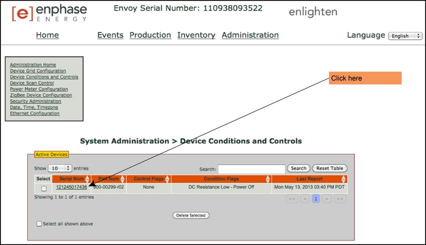
Troubleshooting an Enphase System
Overview
This document describes troubleshooting flows and procedures only. For product and installation
information, refer to http://www.enphase.com/support.
Troubleshooting areas covered in this document include:
Envoy and Communications Issues
Microinverter / PV Module Issues
Messages and Alerts
Best Practices
Use the troubleshooting table on page 9 to find information on a problem according to category:
Production issues
Envoy not reporting
Microinverter not reporting
General troubleshooting
8 2014 Enphase Energy Inc. August 2014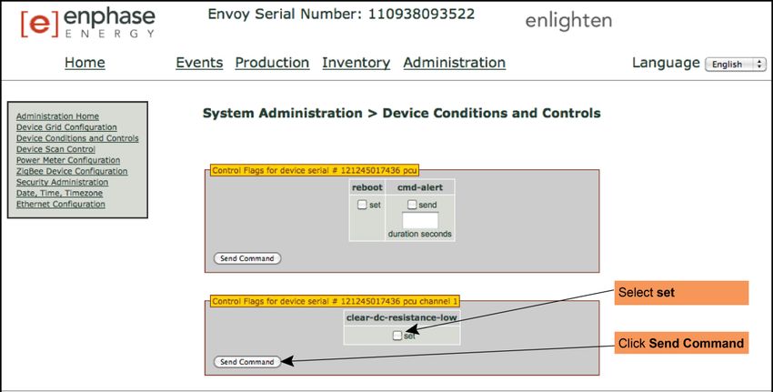
Troubleshooting an Enphase System
Troubleshooting Topics
Use the following table to find information on a problem by category.
Topic Page
Production issues
ACFOOR (AC Frequency Out of Range) 33
ACVOOR (AC Voltage Out of Range) 34
When an entire branch or multiple branches are impacted 34
When only a few microinverters are impacted 36
Critical Temperature 37
DC Too Low 39
DC Too High 40
Device Produced No Power 40
GFI tripped 41
DC Resistance Low – Power Off 37
Grid Gone 42
Over Temperature 43
The unit under review shows low production. 28
Why is one unit showing 0W production when adjacent units are productive? 29
Notes on Open Circuit Voltage 30
Other Things to Check 30
Envoy not reporting
Envoy not Reporting 40
Gateway Failure 40
LCD displays “Envoy Failure” 12
LCD periodically shows “-Web” for minutes or hours at a time. 17
LCD shows a good IP, but also shows “-Web” 17
LCD shows a non-routable/self-assigned IP address and also shows “-Web” 15
The Envoy cannot get a “+Web” even though all premises networking is intact 20
The Envoy is using a static IP and cannot get a web connection 17
Microinverter not reporting
Microinverters are not detected / Power line communication level is low/poor 22
Microinverter Failed to Report 43
My panels are dark in Enlighten and no production value is displayed 31
General
A physical Ethernet connection is not practical at this site 11
Are my power line communication bridges working? 19
Can I use a dial-up Internet connection with the Envoy? 20
Enlighten will not allow me to select the panel 31
9 2014 Enphase Energy Inc. August 2014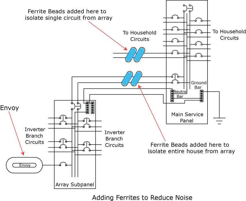
Troubleshooting an Enphase System Topic Page How to get further training on Enphase power line communication 26 How to identify an interfering load 24 I would like to see my panel’s production history 31 Internet service is not available on site 18 LCD displays "Scanning Inhibited" 12 LCD displays “Reset Clock” 12 LCD is completely blank 12 Run a report to view production history 31 The DSL modem at the site has only one Ethernet port, and it is being used 17 The Envoy is in a circuit on the primary load-center, the solar circuits are on a 24 downstream subpanel The Envoy is slowing down other Internet traffic 19 The Microinverter LEDs are flashing orange 28 The Microinverter LEDs are flashing red 28 The Microinverter LEDs are not lit 28 There is an event or alert message on the system 32 This is a Line-side Tap (or Supply-Side, or PLC) Installation 25 Use the Graph widget to view production history 32 When do I need an additional Envoy? 25 Zigbee Device Failed to Report 43 Zigbee USB Stick Removed 43 Best Practices Installation sequence 44 Care of the solar array 44 10 2014 Enphase Energy Inc. August 2014
Troubleshooting an Enphase System
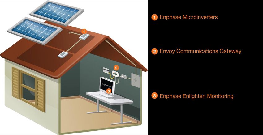
Envoy and Communications Issues
The following sections describe possible problems and
solutions. Areas include:
Envoy Issues
Networking and Internet Issues
Power Line Communication Issues between
the Envoy & Microinverters
WARNING: Do not attempt to repair the
Enphase Envoy; it contains no user-
serviceable parts. Tampering with or
opening the Envoy will void the warranty. If
the Envoy fails, contact Enphase customer
service to obtain an RMA (return
merchandise authorization) number and
start the replacement process.
Envoy Issues
Envoy
A physical Ethernet connection is not
practical at the site
Broadband
The location for the Envoy yields a good signal- Router
strength between the Envoy and the Microinverters
(over the power lines), but it is remote from the
router. An Ethernet cable from the broadband router
to this spot is not practical.
Try these solutions:
Power line
Use an Enphase Wireless Adapter (order
communication
WF-01) as shown.
bridges
Use Enphase power line communication
bridges (order ELPC-01) with the Envoy as
shown.
Or, you can use a third-party wireless
Ethernet bridge (available at computer Wireless
stores). Adapter
Envoy
Wireless
Router
11 2014 Enphase Energy Inc. August 2014Troubleshooting an Enphase System
LCD is completely blank
1. Try another outlet (just in case).
2. If this fails, the Envoy unit must be replaced. There are no field replaceable parts for the Envoy.
Contact Enphase Customer Support support@enphaseenergy.com.
LCD displays “Reset Clock”
If the Envoy has a current Internet connection, let it use this connection to retrieve an upgrade from
Enlighten. This may take up to 20 minutes, depending upon the speed of the connection. You may need
to contact Enphase Customer Support to initiate the upgrade.
LCD displays “Envoy Failure”
This message displays after the Envoy has tried unsuccessfully three times to initialize. This may happen
when the Envoy has been moved, and its initialization process interrupted.
1. Unplug the Envoy from the electrical outlet, and then plug it in again. Leave the Envoy in place for
at least 15 minutes.
2. If it continues to display Envoy Failure or if it never moves beyond the Initialization stage, contact
Enphase Customer Support.
LCD displays "Scanning Inhibited"
This message displays after an installer has used the Installer's Toolkit to provision the Envoy. Leave the
Envoy in this condition for normal operation. If you need to re-enable scanning, contact Enphase
Customer Support (support@enphaseenergy.com).
12 2014 Enphase Energy Inc. August 2014Troubleshooting an Enphase System
Networking and Internet Issues
The Enphase Envoy Communications Gateway operates much as another computer does. As such,
many of the troubleshooting steps for the Envoy are the same as those for other computers at the site.
Issue: Wireless Adapter Wi-Fi Problems
If the wireless installation fails, try these solutions:
Verify that the Envoy is at version "R3.8" or later. If needed, upgrade the Envoy as directed.
Verify that the wireless adapter is fully seated in the Envoy USB port.
Verify that the Envoy has two USB ports and that the USB adapter is in the left port (looking
at Envoy from the front). Envoys with only one USB port do not support Wi-Fi.
Remove power from all units in the chain, then apply power in this order: 1) modem, 2)
router, and 3) Envoy.
If the Envoy is installed in an enclosure and you are using the wireless adapter, that enclosure
must be plastic or fiberglass to allow wireless communication. Metal enclosures impede wireless
communication.
Stucco and plaster wall construction may contain metal mesh, which can affect wireless range. If
you cannot see your router or access point in the list on the Envoy, or cannot maintain a
connection, relocate the Envoy to be closer to your router or access point.
If you remove the wireless adapter, wait about 15 seconds before re-inserting it.
Issue: How Set Up Wi-Fi without Wi-Fi WPS
The Envoy with wireless adapter supports several wireless security protocols:
Wi-Fi WPS
WEP Open System
WEP Shared Key
WPA-PSK
WPA2-PSK
WPA-EAP
WPA2-EAP
If the router does not support Wi-Fi WPS or you do not wish to use Wi-Fi WPS, follow these steps to
establish a wireless connection using one of the listed protocols.
a. Verify that the wireless adapter is fully seated in the left USB port (looking at Envoy from the
front). Envoys with only one USB port do not support Wi-Fi.
b. Plug the included Ethernet cable either to a laptop directly or to a PC on the same broadband
router network.
c. Access the Envoy Administration page. Enter the IP address of the Envoy LCD in the Internet
browser.
d. Enter the default login credentials for the Administration menu:
Username: admin
13 2014 Enphase Energy Inc. August 2014Troubleshooting an Enphase System
Password: admin
e. From the Administration menu, select Wi-Fi Configuration. This menu option is available only
when the wireless adapter is installed in a USB port on the Envoy.
f. The interface displays a list of available networks.
g. Click a network to select it and enter the password.
If you don’t see your network listed, the router
SSID broadcast may be blocked. If so, enter the
SSID (name) and password.
If your network is not blocked and not listed, click
Re-Scan to refresh the list of networks.
Status messages appear during the connection
process, including “Connection Test” and
Confirmation”.
h. Click Join Network when displayed.
After joining, the network displays in bold in the list of
available networks.
i. Disconnect the Ethernet cable.
Within two minutes, an updated IP address displays
on the Envoy LCD screen, indicating that a wireless
connection is established.
Within a minute, the Envoy LCD screen displays
+Web, indicating a successful connection to
Enphase.
14 2014 Enphase Energy Inc. August 2014Troubleshooting an Enphase System
LCD shows a non-routable/self-assigned IP address AND shows “-Web”
The Envoy has no connection to the Enlighten software platform. If the Envoy shows a self-assigned IP
(169.254.120.1) and “-Web”, either a physical Ethernet connectivity issue is preventing it from obtaining a
DHCP-issued IP address, or there is a setup problem.
What is DHCP?
During the power-up sequence, the Envoy requests a DHCP-issued IP address from the
broadband router. The router obtains an address from a pool of available IP addresses from a
Dynamic Host Configuration Protocol (DHCP) server. The DHCP server ‘leases’ an IP address to
each device in the Local Area Network (LAN). The Envoy, like other computers in the LAN, uses
the DHCP IP address as the path to the Internet.
Troubleshoot as follows.
1. Verify the Envoy connection to the router.
a. Verify connection. The Envoy requires connection to a router, with the CAT5 cable that came
with the Envoy or by installing an Enphase Wireless Adapter (order WF-01 separately).
b. Verify that the Envoy is connected to a broadband router. A switch or hub cannot be
substituted for the router.
i. Determine the make and model of the router. This will help you discover if it is a true
router, rather than a hub or switch.
ii. A switch or hub placed between the modem and the ISP connection may also cause
this problem.
c. Check that the Local Area Network (LAN) port LED is lit. The LED is on the rear of Envoy
next to the LAN port., is the Envoy network port light lit? If so, the Envoy is waiting for a
response from Enlighten, and will show “+Web” soon. If not, reseat connections or try another
CAT5 cable.
2. Did the Envoy previously have an Internet connection at this site?
a. If so, what has changed? Is it a new router or ISP? Was there a power outage?
b. If yes to any of these, remove power from all units in the chain, then apply power again in this
order: Cable/DSL Modem, Router, and Envoy.
c. If the router was replaced,
make sure the new device
is actually a router, not a
hub or a switch.
d. Look up the site in
Enlighten. According to
the graph, when did this
Envoy last report (last
date/time shown in the
energy production graph)?
What changed at that
point in time?
e. Try using the Envoy menu
button to “Get New IP
address.” Press and hold
15 2014 Enphase Energy Inc. August 2014Troubleshooting an Enphase System
the Envoy Menu button; after two seconds you will see the Envoy menu. Continue holding the
Menu button; when the LCD window displays “Get New IP Address”, release the Menu
button.
f. If using an Ethernet CAT5 cable between the Envoy and router, try replacing this cable.
g. Is there an “Envoy not Reporting” event in Enlighten? If so, see page 40.
3. If Enphase power line communication bridges are in use, check that all LEDs are either on or flashing as
described in “Are my power line communication bridges working?” Try the following:
a. Relocate one of the bridges to a different power outlet, and make sure that neither one is in a
power-strip or UPS battery-backup device.
b. Bypass the bridges and plug the Envoy directly into the Router to eliminate the bridges as the
source of trouble. They may be faulty or they may be too far apart.
c. Replace the Ethernet cables, one at a time, to eliminate these as the cause.
4. Is the router set up with MAC (media access control) filtering? If enabled, MAC filtering prevents the
Envoy from obtaining a DHCP address because the router refuses the DHCP request.
Temporarily disable MAC filtering, add the MAC address of the Envoy to the broadband filter
MAC address list, and then enable MAC filtering.
What is a MAC address?
A MAC address is a unique identifier permanently assigned to a network interface and MAC
filtering uses those addresses as a common security technique. In the router, enter a list of MAC
addresses from the other computers at your site that share the router. Only those MAC addresses
can participate in the router’s network.
5. Is there a firewall set up on the LAN? Most routers either have the firewall disabled or they come with
a basic firewall rule of Allow all outbound traffic but disallow all inbound traffic. This allows you to view
any website, but prevents unsolicited Internet traffic from coming into the premises via the router.
What is a Firewall?
A network firewall is a set of router rules that allow or disallow certain types of inbound or
outbound traffic to your LAN. Firewall rules are specific rules that you can set up to allow or
disallow different types of network traffic.
The Envoy initiates outbound connections to Internet servers. Such connections may be restricted
by firewall rules set up on the site’s broadband router. Broadband routers typically allow all outbound
connections and restrict any or all inbound connections.
If outbound firewall rules are applied at the site, you must configure a static IP address for the
Envoy and add new rules that allow outbound access as follows:
Direction Source Protocol Port Destination
OUT TCP 443 reports.enphaseenergy.com
OUT TCP 443 securereports.enphaseenergy.com
OUT TCP 443 home.enphaseenergy.com
OUT TCP 2020 home.enphaseenergy.com †
OUT UDP 123 us.pool.ntp.org
† Port 2020 is an optional support port used when there are issues with the standard HTTPS port (443).
16 2014 Enphase Energy Inc. August 2014Troubleshooting an Enphase System
The Envoy connects to these servers using their DNS names. If you add firewall rules for Envoy
reporting, Enphase recommends using the DNS names rather than the underlying IP addresses as
the IP addresses are subject to change without notice.
WARNING: Do not change the Envoy DHCP setting to use a static IP address unless you
also reserve the same IP address on the broadband router. See the section on DHCP
Reservations in your router's setup manual. Failure to reserve the static IP address on the
router results in duplicate IP addresses and intermittent Internet connection problems with the
Envoy.
The Envoy is using a static IP and cannot get a web connection
If the site owner prefers not to use DHCP, set up the Envoy to use a static IP address.
Use the Envoy’s web interface to navigate to the Administration page. The Username is “admin”,
and password is “admin”. Click the “Network Connectivity” menu item. This allows you to see if
the Envoy is using DHCP or static IP, and allows you to change this setting if needed.
Click “Check Network Connectivity” to view the Envoy connections.
WARNING: Do not change the Envoy DHCP setting to use a static IP address unless
you also reserve the same IP address on the broadband router. See the section on
DHCP reservations in the router instructions. Failure to reserve the static IP address on
the router will result in duplicate IP addresses and intermittent Internet connection
problems with the Envoy.
For more information on how to use the Envoy Interface, refer to the Envoy Installation and Operation
Manual at http://www.enphase.com/support.
LCD periodically shows “-Web” for minutes or hours at a time.
If the Envoy LCD intermittently shows a good IP and “+Web”, but periodically shows “-Web” for minutes or
hours at a time.
The Internet service may be dropping out periodically. Does this happen with other Internet-
connected devices at the premises? If so, contact the ISP.
Does the Envoy connection drop when another device at the premises obtains an Internet
connection? If so, a switching device at the premises is likely allowing only one Internet
connection at a time. Check the router for this limitation.
If using an Ethernet CAT5 cable between the Envoy and router, try replacing this cable.
LCD shows a valid IP, but also shows “-Web”
The Envoy has no connection to the Enlighten software platform. The LCD shows a valid IP (something
other than 169.254.120.1), but also shows “-Web”.
The Envoy is waiting for a response from Enlighten, and will likely show “+Web” soon. Wait a few
minutes longer.
Check that the Envoy is connected to a broadband router and not a hub or switch.
The router or DSL modem at the site has only one Ethernet port
If the site has only a single-port DSL modem and the system owner’s computer is already using that port,
choose from the following solutions:
17 2014 Enphase Energy Inc. August 2014Troubleshooting an Enphase System
Install a broadband router to allow multiple private LAN connections to the single WAN connection.
See Setup 1 below.
What are LAN and WAN?
WAN = The Wide Area Network is the network beyond your local premises.
LAN = The Local Area Network is the network within your local premises.
Also, if the broadband connection is setup to only allow one Internet-connected host at a time, contact
the ISP to change the account to allow multiple hosts to connect at one time. The ISP may
recommend a router, or you may opt to buy one at a retailer.
If the site has a wireless broadband router, purchase an ENV-120-02, the kit that includes an Envoy
and a Wi-Fi stick. Install it as described in Envoy Installation and Operation Manual at
http://www.enphase.com/support.
Internet service is not available on site
Consider buying an air card or hot spot. There are some cases where this is the only Internet connectivity
option for the site. Air cards are also called EVDO or CDMA cards and typically provided by Sprint,
Verizon or AT&T. Purchase an air card compatible router (e.g., Cradlepoint MBR 95). Plug the air card
into the indicated port on the router to create a LAN at the site. See Setup 2 below.
After installing the air card, you can then install the Envoy as described in the Envoy Installation and
Operation Manual at http://www.enphase.com/support.
18 2014 Enphase Energy Inc. August 2014Troubleshooting an Enphase System
Are my power line communication bridges working?
Use the status lights to verify connections.
Indicator LED Status
Power On Device is powered on
Off No power
PLC Activity Flashing Activity on power line
Off No activity on power line (should flash
intermittently)
Ethernet Link On There is Ethernet connectivity
Flashing There is Ethernet traffic
Off No Ethernet activity
Issue: Internet Traffic is Slower After Installing a Bridge
Cross talk occurs when a power line communication bridge establishes communication with a bridge in a
neighboring home or business. Crosstalk impacts the volume of Internet traffic. To determine if an
Internet traffic slowdown problem originates from crosstalk, disconnect the bridge from the router. If the
Envoy stays online and the bridge continues to indicate connectivity, you may be gaining connectivity
from another bridge. Reconnect the bridge to the router and disconnect the other bridge from the Envoy.
If the volume of Internet traffic increases, other devices may be gaining access to the Internet through
your bridge. Reconnect the bridge. To prevent crosstalk, use the solution below according to the type of
bridge you have.
Asoka PL9650
1. Verify that both adapters are plugged in to an outlet and that one adapter is
connected via Ethernet cable to the router while the other is connected via
Ethernet cable to the Envoy.
2. Change the password for your pair of bridges so that neighboring devices
can no longer gain access to the Internet through your bridge. Use Asoka’s free, Windows-only
configuration software to change the password. Go to the "Advanced" screen of the configuration
utility and change the password. Follow any additional instructions. The configuration software is
available at http://www.asokatech.com/downloads-page.
Asoka PL9660-Q1
1. Verify that both adapters are plugged in to an outlet and that one adapter is
connected via Ethernet cable to the router while the other is connected via
Ethernet cable to the Envoy.
2. On one adapter, press and hold the Sync/Reset button for one second,
then release. The Power LED starts flashing.
3. Within two minutes of releasing the Sync/Reset button on the first adapter, press and hold the
Sync/Reset button on the second adapter for one second. The Power LED starts flashing.
4. Allow 15 seconds for pairing to occur. When pairing is successful, the power LED lights up solid.
ReadyNet EN200
1. Verify that both adapters are plugged in to an outlet and that one adapter is
connected via Ethernet cable to the router while the other is connected via
Ethernet cable to the Envoy.
19 2014 Enphase Energy Inc. August 2014Troubleshooting an Enphase System
2. Press and hold the Sync / Reset button for two seconds on each unit. After this, the Ethernet
light flashes. The units then reset and attempt to link using default factory settings.
Tenda P200
1. Verify that both adapters are plugged in to an outlet and that one adapter is
connected via Ethernet cable to the router while the other is connected via
Ethernet cable to the Envoy.
2. On adapter one, press and hold the Reset/Pair button for two to three
seconds, then release. The Power LED starts flashing.
3. Within two minutes of releasing the Reset/Pair button on adapter one, press
and hold the Reset/Pair button on adapter two for two to three seconds, then release it. The
power LED starts flashing.
4. The Power and PLC LEDs on both adapters display a solid light to indicate that an encrypted
private network is successfully created.
The Envoy cannot get a “+Web” even though all premises networking is intact
If you have gone through all appropriate troubleshooting exercises and cannot get the Envoy to show a
“+Web” condition and other computers in the LAN are able to get to the Internet, then it may be that the
Envoy has a hardware or networking problem. Contact Enphase Customer Support.
Can I use a dial-up Internet connection with the Envoy?
No. Dial-up Internet connections do not allow consistent communication between the Envoy and
Enphase. As such, Enphase Energy does not support dial-up connections.
20 2014 Enphase Energy Inc. August 2014Troubleshooting an Enphase System
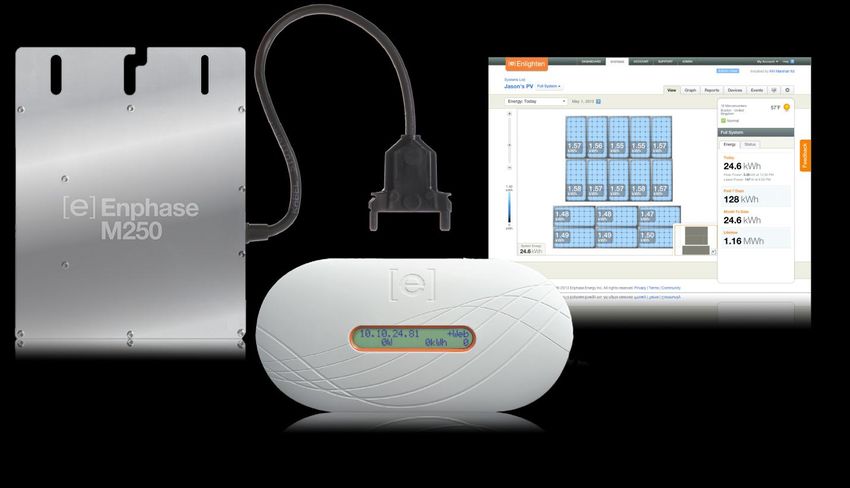
Power Line Communication Issues between the Envoy & Microinverters
Enphase Microinverters use a power line transmission protocol at the site for communication with the
Envoy. All electrical loads at the premises share this common collection of power lines and circuits, and
terminate at the load center, the location of the circuit breakers. The load center is typically found on the
side of the house or building or in the garage. Since the power lines are shared with other loads,
interference can occur, particularly as new devices are plugged in.
Power line communication between the Envoy and the microinverters is completely separate from the
Envoy Internet communication. That is what makes the Envoy a “gateway device”. One side of the Envoy
communicates with the microinverters via the power lines. The other side of the Envoy communicates
with the Internet using a standard Ethernet/network cable plugged into your broadband router.
At power-up, the Envoy performs a power line communication check to determine the strength of the
signal between the microinverters and the Envoy. This check does not assess Internet communications.
During power up, the Envoy performs a communication check. A few minutes after power-up, the Envoy
displays a number of bars from 0 to 5 (figure shows four bars) that indicate the signal strength of power
line communications between the Envoy and the
microinverters.
A signal strength from 3 to 5 bars is usually
sufficient. Level: [ ]
A signal strength of 1 or 2 bars is workable, Devices: 25
but not ideal. In these cases, relocate the
Envoy to a dedicated outlet closer to the
load center.
Zero bars means that either that you need to relocate the Envoy, or that there are one or more
devices causing interference between the Envoy and the microinverters in the array
Zero bars may also mean that the Envoy has never detected any devices, so you should initiate a
device scan.
21 2014 Enphase Energy Inc. August 2014Troubleshooting an Enphase System
Microinverters are not detected, or, power line communication level is low or poor
If the Envoy LCD level indicator displays 2 or fewer bars,, or you may be seeing “Microinverter Failed to
Report” events.
1. The Envoy may be plugged into an AC outlet that is too far from the electrical load center. Relocate it
to an outlet physically closer to the load center.
2. Is there an unbroken Neutral line from the load center to the solar array branch circuit? This is
required for system communications.
3. Is another device causing interference?
If the Envoy is not detecting the Microinverters in the array(s), or if the event log frequently lists
Microinverter Failed to Report events, then either the power line communication signal strength
is weaker than required, or there is interference on the line from a device at the site.
Unplug any other device that may be sharing the outlet with the Envoy. Use another outlet for the
unplugged device.
The following devices may interfere with power line communications:
power strips and surge protectors on the same circuit
UPS (Uninterruptible Power Supply) / battery backup units on the same circuit
dimmer switches
home automation/security devices that use power line communication
touch lamps
battery chargers (cell phone and laptop chargers)
AC adapters (laptop power cord)
heavy rotating motors (e.g., fans, refrigerators, freezers, water pumps)
workshop equipment (e.g., drill press, table saw, wood routers, planers)
CFLs (Compact fluorescent lights) with failed ballasts anywhere in the home
electronic pest deterrents
GFI outlets
some brands of arc-fault protected outlets (arc-fault breaker)
Determine the source of the interfering load by isolating the Enphase signal from other systems.
The Enphase system transmits at 144kHz, and adequately filters X10 and other signals. but not
all other systems adequately filter the Enphase signal. To best isolate the signal:
Install a PV subpanel to land all the solar branch circuits.
Install a dedicated outlet for the Envoy (and power line communication bridges, if needed) off
the subpanel.
Filter the phase conductors running from the subpanel back to the load center. Ferrite toroids
are an effective, simple filtering mechanism. Refer to
http://en.wikipedia.org/wiki/Toroidal_inductors_and_transformers for more information. Here
is the link to specific model required:
http://search.digikey.com/scripts/DkSearch/dksus.dll?vendor=0&keywords=Epcos+B64290L0
082X087
If this subpanel is remote from the router, you may need power line communication bridges to
span the gap from the Envoy back to the site’s router. However, remember that these bridges
do not help or hinder the power line communication signal between the Envoy and the
microinverters.
If the signal path for the bridges is impeded by the use of the subpanel, you can use a
wireless Ethernet bridge instead.
22 2014 Enphase Energy Inc. August 2014Troubleshooting an Enphase System
4. There may be a Phase imbalance. Have an electrician evaluate the circuit breakers in the load center
to see how many breakers, and of what size, are on each of the two phases of the split-phase 240
VAC service to ensure that the phases are balanced. As a troubleshooting technique, you may want to
try plugging the Envoy into an outlet of a circuit on the other phase or moving the breaker of the circuit
in which the Envoy is plugged onto the other phase.
5. The system may not be energized The PV module powers the microinverter only during daylight
hours, and microinverters communicate only when powered. Perform a device scan or
communication check only during daylight hours. Check for the following conditions:
Are the solar circuit breakers in the “ON” position? For the Envoy to communicate with the
microinverters, the circuit breakers for the solar wiring must be in the “ON” position at the load-
center.
Are the PV modules installed and connected? PV modules power the microinverters, and
microinverters cannot communicate unless powered.
6. Not all the microinverters are detected.
It may be that all of the expected devices have not been detected because not enough time has
passed. After you first energize the system, allow at least 30 minutes for all devices to report.
If the initial 8-hour scan has expired, start a new scan. You can start a new scan from Enlighten
or from the Envoy. To initiate a communication from the Envoy, follow these steps:
Press and hold the Envoy Menu button; after two seconds the Envoy menu displays.
Continue to hold the Menu button; until the LCD window displays “Enable New Device Scan”,
then release.
23 2014 Enphase Energy Inc. August 2014Troubleshooting an Enphase System
The LCD displays Device Scan Active, and the Envoy begins a 30-minute scan (if a longer
scan is not already in progress) to identify all of the microinverters deployed at the site.
Alternatively, if you have an installer account, you can use Enlighten to start a new device scan:
Log into Enlighten, select the site, and click the Settings ( ) icon.
Click the Status tab in the information pane on the right.
Click the Envoy serial number.
Click the Rescan for Devices button.
How to identify an interfering load
If you are unable to resolve the power line communication issue after completing the previous
troubleshooting steps, inspect the load center one circuit breaker at a time. Identify the source of
interference. If there is no subpanel, follow these steps to identify which circuit has the interfering load or
loads.
1. Turn off all circuit breakers except those for the PV array and for the Envoy.
2. Verify that the Envoy and microinverters are communicating.
3. Turn on one additional circuit breaker and wait 10 minutes to see if there is any interference.
4. If not, turn on another circuit breaker and check again.
After completing these steps to find out which circuit has the interfering load, look at the individual loads
on that circuit to determine which device is causing the interference.
The Envoy is in a circuit on the primary load center, the solar circuits are on a
downstream subpanel
If the primary load center is full with no more capacity to add circuit breakers
for solar, add a subpanel. A subpanel is similar to another, “mini” load center
with a small subset of circuit breakers. In these cases, it is best
to add an additional 5-Amp circuit breaker and then run an
outlet off of that subpanel. Plug the Envoy into that outlet, so
that it is close to the PV circuit breakers.
24 2014 Enphase Energy Inc. August 2014You can also read