Heavy Vehicle Interception Site - Design Manual - Manual - TMR
←
→
Page content transcription
If your browser does not render page correctly, please read the page content below
Manual

Heavy Vehicle Interception Site – Design Manual
July 2021
Copyright
© The State of Queensland (Department of Transport and Main Roads) 2021.

Licence

This work is licensed by the State of Queensland (Department of Transport and Main Roads) under
a Creative Commons Attribution (CC BY) 4.0 International licence.

CC BY licence summary statement
In essence, you are free to copy, communicate and adapt this work, as long as you attribute the
work to the State of Queensland (Department of Transport and Main Roads). To view a copy of this
licence, visit: https://creativecommons.org/licenses/by/4.0/

Translating and interpreting assistance
              The Queensland Government is committed to providing accessible services to
              Queenslanders from all cultural and linguistic backgrounds. If you have difficulty
              understanding this publication and need a translator, please call the Translating and
              Interpreting Service (TIS National) on 13 14 50 and ask them to telephone the
              Queensland Department of Transport and Main Roads on 13 74 68.

Disclaimer
While every care has been taken in preparing this publication, the State of Queensland accepts no
responsibility for decisions or actions taken as a result of any data, information, statement or
advice, expressed or implied, contained within. To the best of our knowledge, the content was
correct at the time of publishing.

Feedback
Please send your feedback regarding this document to: tmr.techdocs@tmr.qld.gov.au

Manual, Transport and Main Roads, July 2021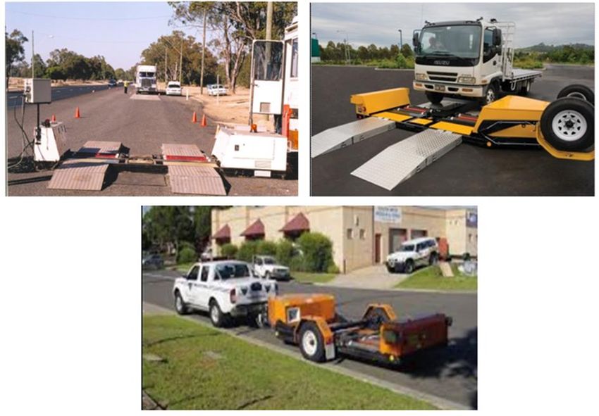
Contents

1     Introduction ....................................................................................................................................4
2     Legislation and standards ............................................................................................................4
3     Terms and definitions ...................................................................................................................6
4     General site layout and components ...........................................................................................8
4.1   Road classification .......................................................................................................................... 8
4.2   Typical HVIS layout ........................................................................................................................ 8
4.3   HVIS equipment .............................................................................................................................. 9
5     Design considerations ..................................................................................................................9
5.1   Operational considerations (activities in HVIS) .............................................................................. 9
5.2   Workplace health and safety considerations ................................................................................ 11
      5.2.1    Operators (Transport Inspector / worker) safety ......................................................... 11
      5.2.2    Pedestrian safety ......................................................................................................... 12
      5.2.3    Driver safety ................................................................................................................ 12
      5.2.4    Variations and modifications ....................................................................................... 12
5.3   Environmental considerations ....................................................................................................... 12
6     General design requirements .................................................................................................... 12
6.1   Geometric design requirements.................................................................................................... 13
      6.1.1     Design vehicle and check vehicle ............................................................................... 13
      6.1.2     Site access geometry (Motorway and Highway HVIS)................................................ 14
      6.1.3     Site access geometry (Rural Road HVIS) ................................................................... 17
      6.1.4     Entry and exit............................................................................................................... 17
      6.1.5     Separation zone .......................................................................................................... 17
6.2   Screening, weighing and inspection requirements ....................................................................... 18
      6.2.1     Screening .................................................................................................................... 18
      6.2.2     Weighing ...................................................................................................................... 22
      6.2.3     Inspection .................................................................................................................... 26
6.3   Surface profile and pavement design ........................................................................................... 28
      6.3.1     General ........................................................................................................................ 28
      6.3.2     Surfacing type.............................................................................................................. 28
      6.3.3     Sprayed seals .............................................................................................................. 28
      6.3.4     Longitudinal slope and crossfall .................................................................................. 29
6.4   Car parking ................................................................................................................................... 30
      6.4.1     General car parking requirement ................................................................................. 30
6.5   Supporting technologies ............................................................................................................... 32
      6.5.1     General ........................................................................................................................ 32
      6.5.2     ITS ............................................................................................................................... 32
      6.5.3     Lighting ........................................................................................................................ 32
6.6   Amenities ...................................................................................................................................... 33
      6.6.1      General ........................................................................................................................ 33
      6.6.2      Site office general specifications ................................................................................. 34
7     Specific design requirements .................................................................................................... 38
7.1   Motorways HVIS minimum design requirements .......................................................................... 38
      7.1.1    Heavy vehicle considerations ...................................................................................... 38
      7.1.2    Site access geometry .................................................................................................. 38
      7.1.3    Screening / weighing / inspection area........................................................................ 38
      7.1.4    Screener ...................................................................................................................... 38

Manual, Transport and Main Roads, July 2021                                                                                                             i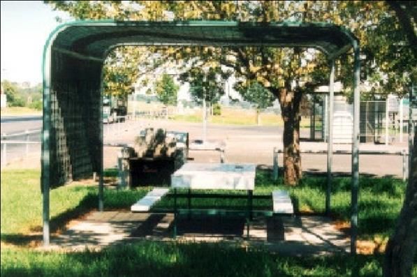
7.1.5           Weighbridge ................................................................................................................ 39
       7.1.6           Motor Vehicle Inspection Unit (MVIU) ......................................................................... 39
       7.1.7           Car parking .................................................................................................................. 39
       7.1.8           Exit and entry ............................................................................................................... 39
       7.1.9           Surface profile and pavement design .......................................................................... 39
       7.1.10          Amenities ..................................................................................................................... 39
       7.1.11          Signing and linemarking .............................................................................................. 39
       7.1.12          ITS and lighting............................................................................................................ 39
7.2    Highway HVIS minimum design requirements ............................................................................. 39
       7.2.1    Heavy vehicle considerations ...................................................................................... 40
       7.2.2    Site access geometry .................................................................................................. 40
       7.2.3    Screening / weighing / inspection areas ...................................................................... 40
       7.2.4    Screener ...................................................................................................................... 40
       7.2.5    Weighbridge ................................................................................................................ 41
       7.2.6    Motor Vehicle Inspection Unit (MVIU) ......................................................................... 41
       7.2.7    Car parking .................................................................................................................. 41
       7.2.8    Exit and entry requirements ........................................................................................ 41
       7.2.9    Surface profile and pavement design .......................................................................... 41
       7.2.10   Amenities ..................................................................................................................... 41
       7.2.11   Signing and linemarking .............................................................................................. 41
       7.2.12   ITS and lighting............................................................................................................ 41
7.3    Rural Road HVIS minimum design requirements ......................................................................... 42
       7.3.1     Heavy vehicles considerations .................................................................................... 42
       7.3.2     Site access geometry .................................................................................................. 42
       7.3.3     Screening / weighing / inspection areas ...................................................................... 43
       7.3.4     Screener ...................................................................................................................... 44
       7.3.5     Weighbridge considerations ........................................................................................ 44
       7.3.6     Motor Vehicle Inspection Unit (MVIU) requirements ................................................... 44
       7.3.7     Car parking .................................................................................................................. 44
       7.3.8     Exit and entry requirements ........................................................................................ 45
       7.3.9     Surface profile and pavement design .......................................................................... 45
       7.3.10    Amenities ..................................................................................................................... 45
       7.3.11    Signing and linemarking .............................................................................................. 45
       7.3.12    ITS and lighting............................................................................................................ 45
Appendix A – Motorway HVIS (Options 1 and 2) .............................................................................. 46
Appendix B – Highway HVIS (Limited Road Reserve and Wide Road Reserve)........................... 48
Appendix C – Rural Road HVIS (AADT5000) ............................................ 50
Appendix D – Concrete Screening Pad ............................................................................................. 52

Tables

Table 2 – Referenced documents ........................................................................................................... 4

Table 3 – Definitions of terms .................................................................................................................. 6

Table 4.1 – Road classification ............................................................................................................... 8

Table 6.1.1 – Length limits of PBS vehicles .......................................................................................... 13

Table 6.1.2 – Motorway and Highway HVIS – site and access geometry ............................................ 15

Table 6.2.1.2.1 – Concrete screening pad dimensions ......................................................................... 20

Table 6.2.2.1 – Concrete weighing area minimum length by truck and weighbridge deck ................... 24

Table 6.2.3.1.1 – MVIU minimum requirements .................................................................................... 27

Manual, Transport and Main Roads, July 2021                                                                                                            ii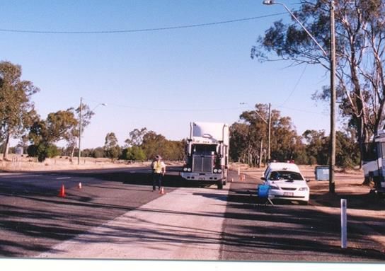
Table 6.3.4 – Longitudinal slope and crossfall for all HVIS ................................................................... 30

Table 6.6.2 – Summary of features and Amenities by Road Classification .......................................... 36

Table 7.2.3 – Highway HVIS concrete pad dimensions ........................................................................ 40

Table 7.3.2.3 – Rural Road HVIS dimensions (by AADT)..................................................................... 43

Table 7.3.3 – Weighing / inspection area dimensions (Rural Road HVIS) ........................................... 44

Figures

Figure 4.2 – HVIS layout (typical) ............................................................................................................ 8

Figure 6.2.1 – Screener ......................................................................................................................... 19

Figure 6.2.1.2.1(a) – Critical tolerance area on screening pad ............................................................. 20

Figure 6.2.1.2.1(b) – Completed screening area with adjacent seal (prior to linemarking) .................. 20

Figure 6.2.1.2.2(a) – Spoon drain at the outlet of the recess ................................................................ 21

Figure 6.2.1.2.2(b) – Pad and pavement level ...................................................................................... 21

Figure 6.2.1.2.3(a) – Screener parts in the recess ................................................................................ 22

Figure 6.2.1.2.3(b) – Screener parts (close up) .................................................................................... 22

Figure 6.2.2.2 – Features of a typical portable scale ............................................................................ 25

Figure 6.2.3.1 – MVIU ........................................................................................................................... 26

Figure 6.2.3.1.1 – Example of positioning MVIU in Rural Road HVIS .................................................. 27

Figure 6.3.3.3(a) – Immediately prior to first spray run ......................................................................... 29

Figure 6.3.3.3(b) – Immediately before placing paper for second spray run ........................................ 29

Figure 6.3.3.3(c) – Immediately after placing paper for second spray run ............................................ 29

Figure 6.3.3.3(d) – Immediately after placing aggregate for second spray run .................................... 29

Figure 6.4.1(a) – Parking ...................................................................................................................... 31

Figure 6.4.1(b) – Abandoned trailer ...................................................................................................... 31

Figure 6.4.1(c) – TC 1387 ..................................................................................................................... 31

Figure 6.6.1 – Bench seat and table with shade ................................................................................... 34

Figure 7.3.2.1 – Minimum width ............................................................................................................ 42

Manual, Transport and Main Roads, July 2021                                                                                                       iii
Heavy Vehicle Interception Site – Design Manual

1     Introduction
This document provides technical guidance for design requirements of Heavy Vehicle Interception
Sites (HVISs) which are designed to provide a safe area outside the road carriageway for the following
purposes:

      •    weighing and inspecting heavy vehicles
      •    inspecting other vehicles
      •    checking the vehicle is being operated in accordance with various legislation, for example,
           dangerous goods, load security and fatigue
      •    undertaking other enforcement activities (for example, random breath testing, traffic offences)
           conducted by police, or other authorised officials
      •    motorists use for short stops to inspect their own vehicles (provided the site is not being used
           for official purposes), and
      •    emergency vehicles use as required.

HVISs comprise different design requirements depending on their location and the local traffic
environment; however, they are broadly categorised as:

      •    motorways, freeways or expressways HVIS
      •    highway HVIS, and
      •    rural road HVIS.

This document outlines the general requirements applicable to all HVISs, as well as the specific
design requirements for each category. This document does not provide guidance for the
determination of warrants nor to the site selection process for the placement of new HVISs.

2     Legislation and standards
Designers must comply with the requirements of the Professional Engineers Act 2002 (Qld).

Completed HVIS designs must comply with the following Queensland legal frameworks:

      •    workplace health and safety legal framework, and
      •    electrical safety legal framework.

Geometric design criteria for HVISs are to be in accordance with the Road Planning and Design
Manual (RPDM) Vol. 3: Guide to Road Design and associated Transport and Main Roads documents.

Additional relevant standards that apply to this document are listed following in Table 2.

Table 2 – Referenced documents

          Reference                                             Title
    AGPT                       Austroads Guide to Pavement Technology

    AS/NZS 1158                Lighting for roads and public spaces
    AS/NZS 3000                Electrical installations (known as Wiring Rules)
    AS/NZS 4836                Safe working on or near low-voltage electrical installations and
                               equipment
    AS/NZS ISO 31000           Risk management – Principles and guidelines
    BCA                        Building Code of Australia
    ES Regulation              Electrical Safety Regulation 2013 (Qld)

Manual, Transport and Main Roads, July 2021                                                                   4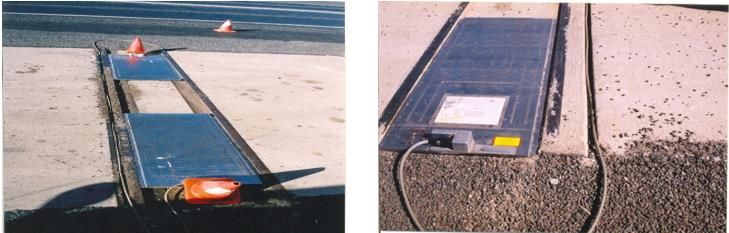
Heavy Vehicle Interception Site – Design Manual

       Reference                                               Title
 ES Act                     Electrical Safety Act 2002 (Qld)
 ES Code of Practice        Electrical Safety Code of Practice 2021 – Managing electrical risk in
                            the workplace
 EPA                        Environmental Protection Act 1994 (Qld)
 EP Regulation              Environmental Protection Regulation 2008 (Qld)
 FSRD Vol 2                 Fauna Sensitive Road Design Volume 2
 Manage and Control         How to Manage and Control Asbestos in the Workplace – Code of
 Asbestos COP               Practice 2020
 MRTS200                    Transport and Main Roads Technical Specification MRTS200 General
                            Requirements for Intelligent Transport Systems Infrastructure
 MRTS225                    Transport and Main Roads Technical Specification MRTS225 Imaging
 MRTS227                    Transport and Main Roads Technical Specification MRTS227
                            Provision of Changeable Message Signs
 MRTS229                    Transport and Main Roads Technical Specification MRTS229
                            Electronic Traffic Control Signs
 MRTS245                    Transport and Main Roads Technical Specification MRTS245
                            ITS Telecommunications Network (ITS TN)
 MRTS263                    Transport and Main Roads Technical Specification MRTS263
                            Standalone Solar (PV) Power Systems
 MRTS38                     Transport and Main Roads Technical Specification
                            MRTS38 Pavement Drains
 MRTS96                     Transport and Main Roads Technical Specification MRTS96
                            Management and Removal of Asbestos
 MUTCD                      Queensland Manual of Uniform Traffic Control Devices (MUTCD)
 NTMR                       National Trade Measurement Regulations 2009(Cth)
 PDS-18                     Transport and Main Roads Pavement Design Supplement
 RA MCV and PBS             Transport and Main Roads Guideline Route Assessment for
                            Multi-Combination Vehicles (MCV) and Performance Based Standards
                            (PBS) Vehicles in Queensland 2020
 RDPM Vol 3                 Transport and Main Roads Road Planning and Design Manual
                            (2nd Edition) Volume 3 Guide to Road Design
 RPDM Vol 6                 Transport and Main Roads Road Planning and Design Manual
                            (2nd Edition) Volume 6 Lighting
 TN115                      Transport and Main Roads Technical Note TN115 Signing and
                            linemarking for heavy vehicle interception sites
 TN158                      Transport and Main Roads Technical Note TN158 Guide to the Use of
                            LED Road Lighting Luminaire
 TNM Code of Practice       Transport and Main Roads Transport Noise Management Code of
                            Practice
 TRUM Vol 4 Part 3          Transport and Main Roads Traffic and Road Use Management
                            (TRUM) manual Volume 4 Part 3 Electrical Design for Roadside
                            Devices
 WHS Act 2011               The Work Health and Safety Act 2011 (Qld)
 WHS Regulation 2011        The Work Health and Safety Regulation 2011

Manual, Transport and Main Roads, July 2021                                                         5
Heavy Vehicle Interception Site – Design Manual

            Reference                                         Title
    WHS COP                  The Work Health and Safety Codes of Practice

3        Terms and definitions
For the purposes of this manual, the following definitions apply.

Table 3 – Definitions of terms

                 Term                                            Definitions
    AADT                             Annual Average Daily Traffic
    ALD                              Average Least Dimension (Pavement)
    ANPR                             Automatic Number Plate Recognition
    As-of-right vehicles             Heavy vehicle combinations that are permitted to operate through
                                     gazettes or notices
    A-triple                         A heavy vehicle combination comprising a prime mover and
                                     three semi-trailers connected by converter dollies
    B-double                         A heavy vehicle combination comprising a prime mover,
                                     lead trailer and semi-trailer connected by a fifth-wheel coupling
    B-triple                         A heavy vehicle combination comprising a prime mover,
                                     two lead trailers and a semi-trailer connected by fifth-wheel
                                     couplings
    CCTV                             Closed Circuit TV
    CMS                              Changeable Message Sign
    Department                       Department of Transport and Main Roads
    End-and-end measurement          A measurement method of vehicle mass by adding separate
                                     measurements of the mass of the vehicle, supported singly or in
                                     combination, by different axles of the vehicle
    Entry                            Entry to the HVIS (or exit from the road)
    Exit                             Exit from the HVIS (or entry into the road)
    FSRD                             Fauna Sensitive Road Design
    HSS2-H                           High Stress Single / Single Seal for heavy traffic loadings
    HSS2-M                           High Stress Single / Single Seal for medium traffic loadings
    HVIS                             Heavy Vehicle Interception Sites
    ITS                              Intelligent Transport System
    LG                               Local Government
    LHS                              Left Hand Side
    Long (Short) Duration Sites      HVIS where enforcement personnel spend more (less) than
                                     two hours at a time
    LRR                              Limited Road Reserve
    MCV                              Multi-Combination Vehicle
    MRTS                             Main Roads Technical Specification
    MTBF                             Mean time between failures
    MVIU                             Motor Vehicle Inspection Unit

Manual, Transport and Main Roads, July 2021                                                              6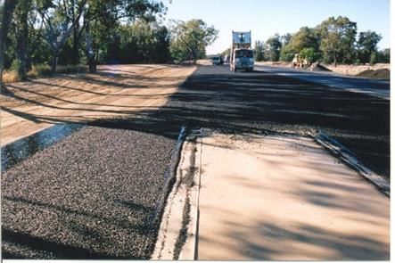
Heavy Vehicle Interception Site – Design Manual

              Term                                               Definitions
 NHVR                                National Heavy Vehicle Regulator
 NMI                                 National Measurement Institute
 Operational Separation              A separation zone that separates the main work area of the
                                     interception site from the adjacent traffic lane. Transport
                                     Inspectors are instructed not to enter inside this zone (refer to
                                     Technical Note TN115)
 OSOM                                Oversize and over-mass vehicles
 Physical Separation                 A barrier system, concrete median or a grassed verge separating
                                     the work area of an HVIS from the through traffic lane. A 1.2 m
                                     flush painted median is not considered as physical
                                     separation (refer to Technical Note TN115)
 PBS                                 Performance Based Standard – Australia’s alternative regulatory
                                     scheme for heavy vehicles, where access is granted on the basis
                                     of the vehicle’s performance in a set of safety and infrastructure
                                     standards
 PIN                                 Penalty Infringement Notice
 PMB                                 Polymer Modified Bitumen
 QPS                                 Queensland Police Service
 RMPC                                Road Management Performance Contract
 RPDM                                Road Planning and Design Manual (2nd Edition)
 RRPM                                Reflective raised pavement markers
 Screener                            A special weighing device placed in a narrow slot in a concrete
                                     pad, over which the vehicles being screened are driven at about
                                     5 km/h
 TI                                  Transport Inspector
 Type 1 road train                   A group of heavy vehicles that comprise two or three trailers,
                                     connected by a converter dolly, including A-doubles and B-triples,
                                     with a maximum overall length of 36.5 m
 Type 2 road train                   A group of heavy vehicles that comprise three or more trailers,
                                     connected by a converter dolly, including A-triples, AB-triples, and
                                     various quad-trailer combinations, with a maximum overall length
                                     of 53.5 m
 VEH SIM                             A vehicle performance software
 vpd                                 Vehicles per day
 VMS                                 Variable Message Sign
 WHS                                 Workplace health and safety
 WIM                                 Weigh-in-Motion
 WRR                                 Wide Road Reserve
 XSS                                 Extreme Stress Double / Double Seal

Manual, Transport and Main Roads, July 2021                                                                 7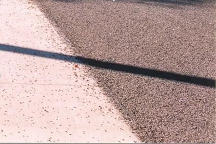
Heavy Vehicle Interception Site – Design Manual
4 General site layout and components
4.1 Road classification
Below are the road classifications relevant to HVIS design.
Table 4.1 – Road classification
Road class HVIS sub-class Description
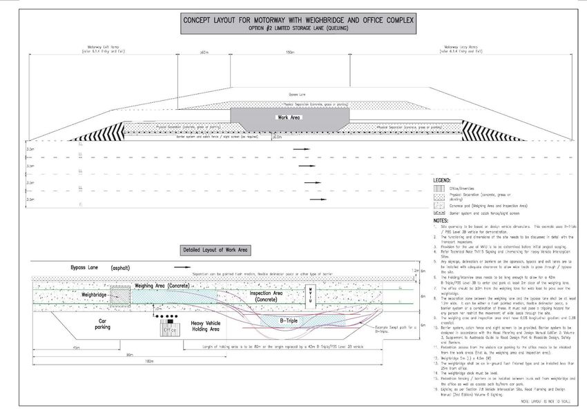
Motorway Option 1 An HVIS in a motorway environment which has adequate
space for vehicle queuing, storage and separation between
the worksites and bypass lane
Option 2 An HVIS in a motorway environment with limited space for
vehicle queuing and office complex
Highway Limited Road An HVIS on a limited road reserve highway
Reserve
Wide Road Reserve An HVIS on a wide road reserve highway
Rural Based on AADT Rural Road HVIS subclasses include those with:
• AADT < 2500
• 2500 ≤ AADT < 5000
• AADT ≥ 5000
4.2 Typical HVIS layout
Figure 4.2 – HVIS layout (typical)
Figure 4.2 shows a typical layout of an HVIS. Although the illustration features are based on the
Motorway HVIS, they are general HVIS illustration. Specific layout details based on application
(motorway, highway or rural road), are shown in the appendices (A – C). Following is a brief
description of each zone in the layout:
1. The car park zone. Refer to Section 6.4 for details.
2. The Road Exit / Deceleration Lane (HVIS entry) is described in Section 6.1.4.
Manual, Transport and Main Roads, July 2021 8Heavy Vehicle Interception Site – Design Manual
3. This area is where vehicles are pre-examined before full inspection is warranted. The initial
interview activity is described in Section 5.1, and screening (where applicable) is explained in
Section 6.2.1.
4. The weighing area is a purpose-built area where the weight of heavy vehicles can be
measured with certified equipment, such as scales or weighbridge. This area is detailed in
Section 6.2.2.
5. The Inspection area refers to the area where Transport Inspectors (TIs) inspect vehicles,
interview the driver and gather data about the vehicle and the driver, to complete either a
Penalty Infringement Notice (PIN) or to prepare a case for later prosecution. Inspection area
requirements are defined in Section 6.2.3. This area may be used for Motor Vehicle Inspection
Unit (MVIU) (Section 6.2.3.1) or may overlap in functions with the holding / interview area.
6. The Holding / interview area refers to the area where TIs may hold vehicles temporarily for
further actions or for grounding of vehicles. Detailed activities are described in Section 5.1.
7. The Road entry / HVIS exit is described in Section 6.1.4.
8. On roads with an Annual Average Daily Traffic (AADT) greater than 2500 vpd, a bypass lane
needs to be considered. Refer to Section 5.1 for details.
9. The separation zone provides a buffer between the worksite and adjacent traffic lane.
Depending on the traffic volume and site risk assessment, the separation zone may be fitted
with a barrier system and/or a traffic island. The separation zone is detailed in Section 6.1.5.
4.3 HVIS equipment
An HVIS must be equipped with different types of devices depending on the specific site requirements.
These devices are detailed in Section 6.2.
5 Design considerations
The design considerations that determine the requirements for the site include:
• the space requirements of the activities on the site
• the dimensions of the heavy vehicles using the route
• the storage space required, and
• the traffic volume.
This section provides details of design considerations. Geometric requirements, including dimensions,
storage space and traffic volumes, are detailed in Sections 6 and 7.
5.1 Operational considerations (activities in HVIS)
The heavy vehicle interception process may involve the following activities
• initial screening of vehicles
• weighing vehicles
• checking vehicle dimensions, brakes and suspensions, and
• interviewing drivers and checking documentation.
Manual, Transport and Main Roads, July 2021 9Heavy Vehicle Interception Site – Design Manual
Operational factors to be considered in design are as follows:
1. The Transport Inspector (TI) issues a directive for the driver of a vehicle to enter the HVIS.
This can be done manually or by using an approved mechanical / electronic device. The major
issues that must be considered are:
a) the installation of Intelligent Transport System (ITS) capability to allow the TI to direct the
driver of an approaching vehicle to enter the site, or
b) the movement of the TI from the facilities area to the position adjacent to the traffic lane,
to issue the directive manually. The following safety issues must be addressed:
i. mutual sight distance (from the TI on the site to an approaching vehicle)
ii. risk of tripping if the area is not level, or has hardware such as reflective raised
pavement markers (RRPM) in a painted traffic island, or
iii. movement of other vehicles through the site.
2. Trucks exiting the through carriageway require a deceleration lane with sufficient distance
after the exit point to allow the vehicles to stop before any queued vehicles.
3. Depending on the type of HVIS and available space, the TI undertaking the initial interview
may require storage for several vehicles on the approach-side of the weighing area for
vehicles waiting to be weighed. Refer to Section 6.1.2 for storage requirements. On roads with
an AADT greater than 2500 vpd, a bypass lane shall be considered. Prior to determining if the
vehicle should be weighed, TIs may check each truck for logbook compliance, load restraint,
dangerous goods and vehicle compliance with dimensions and permits. Empty vehicles are
often instructed to exit the site from the line of trucks via the bypass lane. There are also
occasions when passenger vehicles enter with trucks and must be directed back out into the
traffic lane. This additional movement creates the risk of injury to the TI.
4. When undertaking a compliance check, the TI requires space for mass screening, weighing,
vehicle inspection, driver interviewing (such as logbooks, traffic offences and breaching check)
and vehicle storage. The actual weighing process depends on the operational requirements of
the site. These are determined during the scoping phase of the HVIS design.
a) Screening for axle weights: Using purpose-built screening devices (known as a screener)
to determine whether to perform accurate weighing using certified scales, or
b) Weighing without initial screening: This often applies where a site is equipped with a
weighbridge. Refer to Section 6.2 for further details regarding weighing and screening.
The enforcement activity may also involve the use of MVIU which requires additional space for
its operation. This is an optional function and is restricted to certain sites.
Refer to Section 6.2.3, for further details regarding the MVIU.
5. Detained vehicles require a holding bay on the departure side of the weighing device, unless
there is a suitable holding area near the site where vehicles can be directed to go. Ideally, this
area should allow for any necessary offloading to be undertaken. In addition, the area shall
allow for safe access to both sides of the vehicle by TIs to complete their records. The TIs will
use this area for interviewing the driver, while preparing the breach report or completing the
PIN. This area should have sufficient space and width to permit exiting vehicles to safely
bypass any stationary vehicles and TI / driver adjacent to the vehicle.
6. The safe departure from the site involves the provision of an acceleration lane and merge
taper appropriately designed to enable the heavy vehicle to safely merge with through-traffic.
The acceleration lane should allow the design heavy vehicle to accelerate to a speed of no
less than 20km/h below the mean free speed of the through-traffic. Refer to RPDM Vol 3
Manual, Transport and Main Roads, July 2021 10Heavy Vehicle Interception Site – Design Manual
Part 4A Unsignalised and Signalised Intersections. In the absence of local data, the mean free
speed can be assumed to be the posted speed limit.
7. Office and/or amenities are located so that the distance between the major activities area and
the office area is reduced to a minimum. It is recommended that this area is located adjacent
to the weighing area, but away from through-traffic. In most sites, the office and/or amenities
area includes the provision for car parking. A simple shelter, or shed with tables, should be
provided where the function is of long duration operations. Full office accommodation shall be
provided for HVISs at motorway sites. Refer to Appendix A for typical site layouts. Refer to
Section 6.6 for further details on the provision of amenities.
8. Where enforcement sites are required for both sides of the road to cover each travel direction,
they need not be located directly opposite each other, although this is desirable to simplify the
logistics of providing personnel for both directions. If they are not located opposite each other,
the first one encountered should be for that direction of travel, to avoid drivers being alerted by
those who have already been intercepted or have passed the site.
5.2 Workplace health and safety considerations
The department is responsible for providing a safe environment for all HVIS users.
Workplace health and safety procedures for HVIS works, are to be in accordance with the
Work Health and Safety Act 2011 (Qld) and the safety standards required by the department.
5.2.1 Operators (Transport Inspector / worker) safety
The interception site is a workplace and, as such, the designer must be aware of the various safety
issues. It is important that the conflict areas, circled in Figure 4.2, are accommodated in the design,
and the clearances outlined in the relevant road type sections of this document are achieved to
facilitate a safe working environment.
The TIs are issued with site specific operating instructions that incorporate any design considerations
regarding how the site was intended to be used and what risks were (or were not) mitigated in the
design phase. This is typically in the form of a work method statement and may include a risk register
for the site.
The method of activating and deactivating signs requires consideration by the designer. A TI is
required to open and close these signs at night and under traffic. Some locations may necessitate the
provision of a small amount of earthwork to provide for a parking area for the TI's vehicle.
Visibility to the start of the exit tapers and the end of the entrance taper should be greater than the
heavy vehicle stopping-distance based on comfortable deceleration and should be carefully
considered in the context of the traffic volume and design speed of the major road.
The transition from the through-road to the HVIS is also a significant consideration. The relative slopes
and crossfalls of the pavements of each will generally be different. It will be necessary to ensure that a
safe transition between the two is provided.
Where the HVIS is exposed to extreme noise level caused by heavy traffic volume and noise barriers
are required for mitigation, these shall be designed in accordance with the department's
Transport Noise Management Code of Practice.
Manual, Transport and Main Roads, July 2021 11Heavy Vehicle Interception Site – Design Manual 5.2.2 Pedestrian safety Appropriate fencing or barriers must be provided around the perimeter of Motorway HVIS, to prevent pedestrians accidently accessing other carriageways. Fencing should be designed and located such that it does not constitute a hazard for road traffic. This fence is not to be placed across the entry and exit carriageways. Catch fencing shall be provided in conjunction with the barrier system where the site is located, adjacent to a road with an AADT of more than 50,000 vpd, or if a risk has been identified in the risk assessment. Fencing in Highway and Rural Road HVISs is optional and is subject to safety assessment and consultation with the department. 5.2.3 Driver safety Provision of a sight screen shall be considered in Motorway HVIS to avoid drivers on the through-traffic from being distracted by the activities in the HVIS. 5.2.4 Variations and modifications Designers and constructors should ensure that any variation or modification to the site does not compromise the standard of safety detailed in this manual and that variations and modifications are captured in a satisfactory risk register, with risks mitigated and that the site-specific safety procedures reflect these. All variations and modifications shall be recorded in accordance with RPDM Vol 3 Part 8 Process and Documentation. 5.3 Environmental considerations All environmental considerations shall be in accordance with the requirements of the Environmental Protection Act 1994 (Qld), the Environmental Protection Regulation 2008 (Qld) and the RPDM Vol 3: Guide to Road Design Part 6B: Roadside Environment. There is a likelihood that asbestos may be present on a site being designed. Consequently, designers should flag this in their design documentations, by including an instruction or recommendation that the contractors check for asbestos in accordance with Transport and Main Roads Technical Specification MRTS96 Management and Removal of Asbestos and approved departmental processes. Where there is a potential impact on fauna in the vicinity of a proposed HVIS, it may be necessary to collect run-off from the site and process it in the appropriate way to avoid contamination of waterways. Further, it may be necessary to provide for the containment of spillage that may occur on the site. Traps and retention basins should be designed into the scheme where appropriate. For additional specific guidelines relating to design in a fauna environment, refer to Fauna Sensitive Road Design Vol 2. 6 General design requirements This section defines the general requirements for HVIS design and the common aspects of site geometry, layout, equipment and surfacing. Specific HVIS requirements are defined in Section 7. Manual, Transport and Main Roads, July 2021 12
Heavy Vehicle Interception Site – Design Manual

6.1       Geometric design requirements

6.1.1      Design vehicle and check vehicle

The designer shall determine the design vehicle for an HVIS in consultation with the Principal. It
should be the largest Multi-Combination Vehicle (MCV) currently permitted and envisaged to operate
on the adjacent state-controlled road. The choice of design vehicle must consider requirements for
future vehicles approved under the National Heavy Vehicle Regulator's Performance Based
Standards (PBS) scheme. For guidance on the department's design requirements and PBS vehicle
design parameters and other characteristics, refer to the department's webpage Assessing routes for
multi-combination vehicles in Queensland or guideline Route Assessment for Multi-Combination
Vehicles (MCV) and Performance Based Standards (PBS) Vehicles in Queensland 2020. The design
for the site will also need to consider oversize and over-mass (OSOM) vehicles along the route (typical
OSOM length and width limits are 35 m and 5.5 m respectively although vehicles may exceed these
dimensions with an approved permit).

An appropriate checking vehicle (usually the next largest design vehicle) should be used to ensure
satisfactory operation of an occasional larger vehicle. Checking vehicles may operate with reduced
clearances. Refer to the department's RPDM Vol 3 Part 4 Intersections and Crossings – General, for
further guidance.

The following overall lengths and swept path template information has been sourced from the
department's webpage Assessing routes for multi-combination vehicles and is summarised here for
ease of reference. For vehicle length requirements, the upper length limit for PBS Class B vehicles
should be adopted to enable future weighing and safe operation of these vehicles within the HVIS.

Table 6.1.1 – Length limits of PBS vehicles

                                                  Vehicle combination upper length limits (m)
      PBS vehicle access class
                                                    Class A                             Class B
                Level 1                                                 20.0
                Level 2                               26.0                                30.0
                Level 3                               36.5                                42.0
                Level 4                               53.5                                60.0

Based on previous research, the following 'as of right' combinations may be substituted for PBS level
vehicles:

      •    The 26-metre B-double template can be used to assess the suitability of routes for B-doubles
           and PBS Level 2 vehicles.
      •    The 36.2-metre A-double and 35.4-metre B-triple templates can be used to assess the
           suitability of routes for A-doubles, B-triples, AB-triples, and PBS Level 3 vehicles.
      •    The 53.4-metre A-triple template can be used to assess the suitability of routes
           for A-triples, AAB-quads, and PBS Level 4 vehicles. It may also be used as a substitute for
           quad combinations, as such combinations are expected to have equal or better
           swept path performance.

Manual, Transport and Main Roads, July 2021                                                              13
Heavy Vehicle Interception Site – Design Manual
6.1.2 Site access geometry (Motorway and Highway HVIS)
Motorways or Highways HVISs shall be designed to allow for the following:
• two or more crews for extended periods
• one vehicle being weighed
• one vehicle being inspected, and
• minimum of one, up to four vehicles in the queue.
Lengths shall be calculated based on the guidelines in Section 6.1.1.
The width required for these sites must allow for the operating area, plus a bypass lane for vehicles to
bypass the vehicle being inspected, plus adequate space to park the TI's or QPS vehicles. The
minimum width (excluding the area for parking) should be 12.7 m. Parking space for four cars should
be provided, typically 30m long by 2.3m wide for parallel parking.
All Motorway and Highway HVISs shall have provisions for the use of the MVIU, unless departmental
motor vehicle inspection centres are in proximity. Refer to Sections 7.1.6 and 7.2.6 for further details
for MVIU in Motorway and Highway HVISs respectively.
The bypass lane shall have a physical separation from the work area. The treatment will vary
according to the risk assessment carried out for each site. However, it must cater for the risk of
motorists confusing an exit ramp to the local road network, resulting in motorists speeding through the
bypass lane adjacent to where the TIs are working and/or truck drivers are walking.
Fencing in Motorway HVISs shall be provided as a WHS measure, whereas fencing in the
Highway HVIS is subject to a safety assessment by the designer (refer to Section 5.2.2). Any
treatment deemed relevant by the designer (for example, a barrier system) shall be in accordance with
the department's RPDM, Standard Drawings and Technical Specifications. Catch fencing shall be
provided in conjunction with the barrier system where the site is located adjacent to a road with AADT
more than 50,000 vpd, or if a risk has been identified in the risk assessment.
Provision of sight screening shall be considered as a safety measure to the drivers on motorway (refer
to Section 5.2.3).
Catch fencing is designed to catch debris for the safety of people within the HVIS (that is, tyres,
debris from a crash).
A sealed shoulder of the appropriate width (typically 0.3m) shall be provided around the outside
perimeter of the site. This shoulder will be constructed concurrently with the HVIS and is separate
from the roadway shoulder. The HVIS shoulder shall be constructed to the same standard as the
HVIS pavement, so that the shoulder and site pavement are homogenous.
Table 6.1.2 is a summary of Motorway and Highway HVIS site and access geometry minimum
requirements. The highway values apply to both wide reserve and limited reserve HVISs.
Manual, Transport and Main Roads, July 2021 14Heavy Vehicle Interception Site – Design Manual
Table 6.1.2 – Motorway and Highway HVIS – site and access geometry
Features and Motorway HVIS Highway HVIS
Comment
dimensions Length (m) Width (m) Length (m) Width (m)
Physical separation – ≥6 – ≥3 For Motorway HVIS, a physical barrier must be provided if there is a ramp to
from adjacent traffic the site that resembles an exit ramp for a motorway. Catch fencing should be
lane provided in conjunction with a barrier system if AADT > 50,000 or risk is
identified.
For Highway HVIS, the width of separation (grass or concrete median) must
be determined to suit site layout, AADT and method of operation. The
preferred width is 5 m.
Bypass lane – ≥ 4.8 – ≥4 Must have physical separation between bypass lane and work area.
Bypass lane shall be wide enough to allow for wide loads.
For Highway HVIS, default widths are 4 m or 4.5 m. The width may need to be
increased in consultation with the Principal.
Weighing area Should have adequate clearance around the weighbridge, to allow wide loads
(including to pass.
weighbridge) The length of the weighing area of Motorway HVIS, is based on 42 m long
5m deck ≥ 90* ≥ 4.8* ≥ 90* ≥ 4.8* design vehicle and 5 m deck weighbridge. Where the design vehicle varies, or
weighbridge a different dimension weighbridge is used, the length of the weighing area will
need to be recalculated. Refer to Table 6.2.2.1.
Nil weighbridge – ≥ 80# ≥ 3.5#^ A weighbridge is optional in Highway HVIS.
or
* with weighbridge.
≥ 50^
# without weighbridge, screener option provided.
^ without weighbridge, screener option not provided.
Inspection area ≥ 50 ≥ 4.5 ≥ 50 ≥ 4.5 If the HVIS is designed to accommodate the use of MVIU, the width shall be
adequate to accommodate the unit and the supporting facilities, or at least
4.8 m. Refer to Table 6.2.3.1.1.
Manual, Transport and Main Roads, July 2021 15Heavy Vehicle Interception Site – Design Manual
Features and Motorway HVIS Highway HVIS
Comment
dimensions Length (m) Width (m) Length (m) Width (m)
Heavy vehicle ≥ 80 ≥6 ≥ 50* ≥ 4.5* Processing and standing area, to allow for a Level 3B vehicle and B-double
holding interview or or trailers to be parked and for long interviews and grounding.
area The width for accessing the parking area should be verified in V-path.
≥ 80# ≥ 6#
* HVIS with Limited Road Reserve.
# HVIS with Wide Road Reserve.
Storage lane for ≥ 60 ≥ 3.5 ≥ 60 ≥ 3.5 For Motorway HVIS: 180 m length is preferred to allow for
queuing four Level 3B vehicles to be queued with a 2 m gap between each vehicle.
For Highway HVIS: 90 m length is preferred.
Sealed shoulder – 0.3 – 0.3 Must be provided around the outside perimeter of entire site.
MVIU – 4.8 – 4.8 Note: MVIU is optional for Highway HVIS.
The MVIU should be placed such that the wheel paths are lined up with the
weighing path, to minimise steering adjustments required to manoeuvre the
vehicle onto and off the unit. The concrete pad width needs to be increased to
4.8 m on all sites with an MVIU.
Car parking 30 ≥ 2.3 30 ≥ 2.3 Accommodate up to four cars. Width and length assume parallel parking;
(parallel) however, this may vary for different parking style.
Extra width may be required to accommodate TI's vehicle which may have
varying width requirements, for example, ute canopies.
Typical site width – ~23 ~12.7* Excluding parking for heavy vehicles and cars.
~20# * HVIS with Limited Road Reserve.
# HVIS with Wide Road Reserve.
~ approximate
Manual, Transport and Main Roads, July 2021 16Heavy Vehicle Interception Site – Design Manual 6.1.3 Site access geometry (Rural Road HVIS) Site access geometry for Rural Road HVIS shall be in accordance with Section 7.3.2. 6.1.4 Entry and exit In this section, the term 'exit' denotes vehicles exiting the traffic stream and entering the HVIS. Conversely, the term 'entry' denotes vehicles exiting the HVIS and entering the traffic stream. 6.1.4.1 Exit requirements An exit ramp or deceleration lane is required to enable vehicles to safely diverge from the through-lane/s and enter the HVIS without impeding on the through-traffic. Sufficient deceleration length is required, to allow the design heavy vehicle to safely decelerate and stop, prior to any queued vehicles within the HVIS. Heavy vehicles require longer distances than cars do to come to a complete stop and, therefore, deceleration lengths need to be based on design heavy vehicle deceleration rates. The design of exit ramps must be in accordance with RPDM Vol 3 Part 4C Interchanges. The design of deceleration lanes and deceleration lengths must be in accordance with RPDM Vol 3 Part 4A Unsignalised and Signalised Intersections, using a maximum rate of deceleration of 2.5 m/s2 to allow for the increased braking distance required for heavy vehicles. Swept path analysis for the design and check vehicles must be undertaken to optimise ingress and egress, achieve minimum clearances and ensure that these vehicles can manoeuvre onto the weighing and testing facilities within the site. The 'design vehicle' and 'check vehicle' are common terms used in road design. The design vehicle will be the largest vehicle that regularly uses the site and the check vehicle will be the next largest vehicle that may occasionally use the site. 6.1.4.2 Entry requirements An entry ramp or acceleration lane is required to enable vehicles to safely exit the HVIS and re-enter the traffic stream on the through-road. Heavy vehicles require very long acceleration distances, which may not be practical to accommodate for an HVIS. Acceleration lanes should allow the design heavy vehicle to accelerate to a speed no less than 20 km/h below the mean free speed of the through-traffic. Refer to RPDM Vol 3 Part 4A. In the absence of local data, the mean free speed can be assumed to be equal to the signposted speed limit. The design of the entry ramp must be in accordance with RPDM Vol 3 Part 4C. Acceleration lengths must be in accordance with RPDM Vol 3 Part 4A, using acceleration rates appropriate for the design heavy vehicle. Vehicle performance software, such as the department's VEH SIM program, must be used to ensure the design heavy vehicle achieves the minimum required speed prior to merge taper. 6.1.5 Separation zone The separation zone is the area located between the road edge line and HVIS (refer to Figure 4.2). It includes the shoulder of the adjacent road and enough additional width to achieve a safety buffer between the HVIS and adjacent traffic lane. Depending on the traffic volume and site risk assessment, the separation zone shall be fitted with a barrier system and/or a traffic island (painted or raised). The separation zone needs to maintain the shoulder width requirements for the functional classification of the road that the HVIS is being constructed on. Manual, Transport and Main Roads, July 2021 17
Heavy Vehicle Interception Site – Design Manual
In determining the separation zone, the designer must consider the following:
• relevant geometric parameters of the adjacent road including design speed, width of
traffic lanes and sealed shoulder, degree of crossfall, longitudinal gradient and so on
• differences in crossfall and longitudinal grade between the HVIS and adjacent road – any
crown lines or changes in crossfall that may be traversed by vehicles will need to be carefully
designed and located, to ensure that vehicle stability is maintained, especially for those with a
high centre of gravity and motorcyclists
• safety barrier requirements and appropriate clearances to the adjacent road, HVIS and its
work areas
• where a safety barrier is determined as not being required, the separation zone will need to be
designed to provide sufficient width (safety buffer) between work areas and adjacent traffic
lanes
• risk of workers tripping if the separation zone adjacent to a work area is not level or has
hardware such as kerbing or RRPM in a painted traffic island, and/or
• the HVIS geometric requirements specified elsewhere in this document.
The separation zone shall incorporate all the relevant design parameters, such that the resulting
design is in accordance with the department's RPDM, Standard Drawings and Technical
Specifications and workplace health and safety requirements.
6.2 Screening, weighing and inspection requirements
Screening, weighing and inspection shall be performed at purpose-built areas having
0.0% longitudinal slope. Crossfall of the areas shall comply with Section 6.3.4.
6.2.1 Screening
Screening refers to the preliminary selection process of identifying potential overloaded heavy
vehicles, before formally weighing the vehicles. Apparent non-compliances identified in the screening
process are not enforceable, due to less achievable accuracies; however, screening allows TIs time to
be mostly spent on clearly overloaded vehicles.
For sites that have weighbridges in operation, typically Motorway HVIS, screening is not warranted.
Screening is predominantly prescribed for Highway and Rural Road HVIS.
Appendix D Concrete Screening Pad illustrates the construction details of a screening pad in a typical
Rural Road HVIS.
As technology keeps evolving, designers shall keep abreast of suitable screening technologies to be
applied in HVIS design; for example, using approach mats instead of a screener will make
constructing the two recesses (refer to Section 6.2.1.2.3) unnecessary. Designers shall identify the
type of screener to be used when determining recess dimensions or whether recess is required.
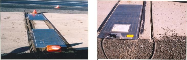
Figure 6.2.1 illustrates the set-up of a screener, with further detail following in sections 6.2.1.1 and
6.2.1.2.
Manual, Transport and Main Roads, July 2021 18Heavy Vehicle Interception Site – Design Manual
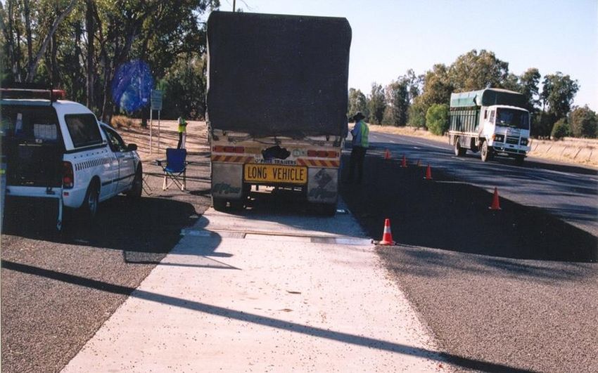
Figure 6.2.1 – Screener
6.2.1.1 Typical screening process
Screening is carried out by using a special weighing device, known as a screener, placed in a narrow
slot in a concrete pad, over which the vehicles being screened are driven at about 5 km/h. The results
are logged by a computer in the TI's vehicle and a decision is then made as to whether the vehicle
should be weighed using certified scales. It takes approximately one minute to screen a B-double,
compared with 15–30 minutes to weigh with scales.
If the screening process indicates that a vehicle is potentially overloaded, then the vehicle is directed
to the weighing / inspection area to be accurately weighed and thoroughly inspected, as well as the
driver being interviewed. The weighing area and inspection areas are provided immediately beyond
the screening area.
6.2.1.2 Screening area requirements
The screening area shall be designed as a concrete pad.
Screening is mostly relevant to Rural Road HVIS and, in some cases, to Highway HVIS in instances
where there are:
• long durations for completing activities at the sites
• short duration sites with an AADT greater than 1,000 vpd, and
• roads having freight traffic with a high likelihood of overloading.
Sections 6.2.1.2.1 to 6.2.1.2.3 detail the typical design of screening area in HVIS.
6.2.1.2.1 Dimensions
The department is currently using the screener of dimensions being 1000 mm x 490 mm x 11 mm.
The dimensions of the concrete screening pad, required to support a screener of these dimensions,
are detailed in Table 6.2.1.2.1.
Manual, Transport and Main Roads, July 2021 19You can also read