MRD 7000 Receiver Decoder Software - User Manual - Sencore
←
→
Page content transcription
If your browser does not render page correctly, please read the page content below
MRD 7000
        Receiver Decoder Software

        User Manual

                                                         October 2019
8175G                 www.sencore.com | 1.605.978.4600    Revision 1.5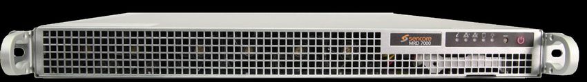
MRD 7000 – User Manual

Copyright
© 2019 Sencore, Inc. All rights reserved.
3200 Sencore Drive, Sioux Falls, SD USA
www.sencore.com
This publication contains confidential, proprietary, and trade secret information. No part of this document may
be copied, photocopied, reproduced, translated, or reduced to any machine-readable or electronic format
without prior written permission from Sencore. Information in this document is subject to change without notice
and Sencore Inc. assumes no responsibility or liability for any errors or inaccuracies. Sencore, Sencore Inc.,
and the Sencore logo are trademarks or registered trademarks in the United States and other countries. All
other products or services mentioned in this document are identified by the trademarks, service marks, or
product names as designated by the companies who market those products. Inquiries should be made directly
to those companies. This document may also have links to third-party web pages that are beyond the control
of Sencore. The presence of such links does not imply that Sencore endorses or recommends the content on
those pages. Sencore acknowledges the use of third-party open source software and licenses in some
Sencore products. This freely available source code can be obtained by contacting Sencore Inc.

About Sencore
Sencore is an engineering leader in the development of high-quality signal transmission solutions for the
broadcast, cable, satellite, IPTV, telecommunications, and professional audio/video markets. The
company’s world-class portfolio includes video delivery products, system monitoring and analysis solutions,
and test and measurement equipment, all designed to support system interoperability and backed by best-
in-class customer support. Sencore meets the rapidly changing needs of modern media by ensuring the
efficient delivery of high-quality video from the source to the home. For more information, visit
www.sencore.com.

Page 2 (77)
MRD 7000 – User Manual

Revision History

  Date          Version     Description            Author
   09/11/17     0.1        First Draft             JDF
   09/14/17     0.2        Revisions               JDF
   09/15/17     1.0        Initial Release         JDF
   11/03/17     1.1        Feature Release         JDF
   01/03/18     1.2        Feature Release         ACD
   04/20/18     1.3        Feature Release         ACD
   5/21/19      1.4        Feature Release         BRW
   3/10/2019    1.5        Feature Release         JF

  Page 3 (77)
MRD 7000 – User Manual
Safety Instructions
Read these instructions
Keep these instructions
Heed all warnings
Follow all instructions
Do not use this apparatus near water
Clean only with dry cloth
Do not block any ventilation openings. Install in accordance with the
manufacturer’s instructions
Do not install near any heat sources such as radiators, heat registers, stoves, or
other apparatus (including amplifiers) that produce heat
Do not defeat the safety purpose of the polarized or grounding-type plug. A
polarized plug has two blades with one wider than the other. A grounding type
plug has two blades and a third grounding prong. The wide blade or the third
prong is provided for your safety. If the provided plug does not fit into your outlet,
consult an electrician for replacement of the obsolete outlet.
Protect the power cord from being walked on or pinched particularly at plugs,
convenience receptacles, and the point where they exit from the apparatus.
Only use attachments/accessories specified by the manufacturer.
Unplug this apparatus during lightning storms or when unused for long periods of
time.
Refer all servicing to qualified service personnel. Servicing is required when the
apparatus has been damaged in any way, such as power-supply cord or plug is
damaged, liquid has been spilled or objects have fallen into the apparatus, the
apparatus has been exposed to rain or moisture, does not operate normally, or
has been dropped.
Do not expose this apparatus to dripping or splashing and ensure that no objects
filled with liquids, such as vases, are placed on the apparatus.
To completely disconnect this apparatus from the AC Mains, disconnect the
power supply cord plug from the AC receptacle.
The mains plug of the power supply cord shall remain readily operable.
Damage Requiring Service: Unplug this product from the wall outlet and refer
servicing to qualified service personnel under the following conditions:
o When the power-supply cord or plug is damaged.
o If liquid has been spilled, or objects have fallen into the product.
o If the product has been exposed to rain or water.
o If the product does not operate normally by following the operating
instructions. Adjust only those controls that are covered by the
operating instructions as an improper adjustment of the controls may
result in damage and will often require extensive work by a qualified
technician to restore the product to its normal operation.
o If the product has been dropped or damaged in any way.
o The product exhibits a distinct change in performance.
Replacement Parts: When replacement parts are required, be sure the service
technician uses replacement parts specified by Sencore, or parts having the
same operating characteristics as the original parts. Unauthorized part
substitutions made may result in fire, electric shock or other hazards.
Page 4 (77)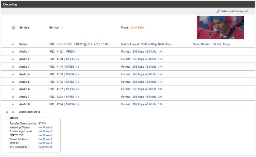
MRD 7000 – User Manual
SAFETY PRECAUTIONS
There is always a danger present when using electronic equipment.
Unexpected high voltages can be present at unusual locations in defective
equipment and signal distribution systems. Become familiar with the equipment
that you are working with and observe the following safety precautions.
Every precaution has been taken in the design of your product to ensure that it is
as safe as possible. However, safe operation depends on you the operator.
Always be sure your equipment is in good working order. Ensure that all points
of connection are secure to the chassis and that protective covers are in place
and secured with fasteners.
Never work alone when working in hazardous conditions. Always have another
person close by in case of an accident.
Always refer to the manual for safe operation. If you have a question about the
application or operation email ProCare@Sencore.com
WARNING – To reduce the risk of fire or electrical shock never allow your
equipment to be exposed to water, rain or high moisture environments. If exposed
to a liquid, remove power safely (at the breaker) and send your equipment to be
serviced by a qualified technician.
To reduce the risk of shock the power supply must be connected to a mains socket
outlet with a protective earthing connection.
For the mains plug the main disconnect and should remain readily accessible and
operable at all times.
When utilizing DC power supply, the power supply MUST be used in conjunction
with an over-current protective device rated at 50 V, 5 A, type: Slow-blo, as part of
battery-supply circuit.
To reduce the risk of shock and damage to equipment, it is recommended to
ground the unit to the installation’s rack, the vehicle’s chassis, the battery’s
negative terminal, and/or earth ground.
Warning: Changes or modifications to this unit not expressly approved by the
party responsible for compliance could void the user’s authority to operate the
equipment.
Page 5 (77)
MRD 7000 – User Manual

Package Contents
The following is a list of the items that are included:

   1.   MRD 7000 Chassis
   2.   MRD 7000 Software
   3.   AC Power Cable
   4.   Breakout or Adapter Cables Depending on Option Modules
   5.   Quick Start Guide

If any of these items were omitted from the packaging please email
ProCare@Sencore.com to obtain a replacement.

Page 6 (77)
MRD 7000 – User Manual

Table of Contents
SECTION 1 OVERVIEW .............................................................................................................................. 9
   1.1         PRODUCT INTRODUCTION .................................................................................................................. 10
   1.2         FRONT PANEL OVERVIEW .................................................................................................................. 11
   1.3         REAR PANEL OVERVIEW .................................................................................................................... 11
SECTION 2 INSTALLATION ...................................................................................................................... 14
   2.1         RACK INSTALLATION ......................................................................................................................... 15
   2.2         AC DUAL REDUNDANT POWER CONNECTIONS....................................................................................... 15
   2.3         MAINTENANCE ................................................................................................................................ 15
   2.4         NETWORK SETUP VIA KVM ............................................................................................................... 15
SECTION 3 WEB-INTERFACE OPERATION ................................................................................................ 16
   3.1     MRD 7000 WEB INTERFACE OVERVIEW.............................................................................................. 17
      3.1.1 Logging into the MRD Web Interface ..................................................................................... 17
      3.1.2 Hiding Unused Inputs .............................................................................................................. 17
      3.1.3 Buttons and Status Indicators ................................................................................................. 17
   3.2     DECODER PANEL .............................................................................................................................. 18
      3.2.1 Configuring Active Input ......................................................................................................... 19
           3.2.1.1         Configuring MPEG/IP Inputs ......................................................................................................... 22
           3.2.1.2         Configuring File Input .................................................................................................................... 24
           3.2.1.3         Configuring ASI Input .................................................................................................................... 26
           3.2.1.4         Configuring SRT Input.................................................................................................................... 27
           3.2.1.5         Configuring RTP Seamless Input (SMPTE 2022-7) ......................................................................... 29
       3.2.2       Configuring Conditinal Access (BISS2 descrambling) .............................................................. 31
       3.2.3       Configuring Transport Stream Processing .............................................................................. 32
       3.2.4       Configuring Decoding and Service Selection ........................................................................... 32
           3.2.4.1         Advanced Configuration................................................................................................................ 33
       3.2.5       Configuring Baseband Processing ........................................................................................... 34
           3.2.5.1         Configuring Video Baseband Processing ....................................................................................... 37
           3.2.5.2         Configuring Audio Baseband Processing ....................................................................................... 38
           3.2.5.3         Configuring Genlock Processing .................................................................................................... 39
       3.2.6       Configuring Baseband Output ................................................................................................ 40
           3.2.6.1         Configuring SDI video .................................................................................................................... 40
           3.2.6.2         Configuring SDI Audio ................................................................................................................... 41
           3.2.6.3         Configuring SDI ANC ...................................................................................................................... 42
      3.2.7 Configuring SMPTE 2110 ........................................................................................................ 44
   3.3     ADMIN PANEL ................................................................................................................................. 45
      3.3.1 File Transfer Management ..................................................................................................... 45
      3.3.2 Disk Usage Statistics ............................................................................................................... 46
      3.3.3 Unit Alias................................................................................................................................. 47
      3.3.4 Changing Unit Password ......................................................................................................... 47
      3.3.5 Profiles .................................................................................................................................... 47
      3.3.6 Configure Unit Networks ........................................................................................................ 48
      3.3.7 Configure SMPTE 2110 Video/IP Networks............................................................................. 50
      3.3.8 Software Support Agreements ................................................................................................ 50
      3.3.9 Licensing ................................................................................................................................. 51
      3.3.10   Date/Time .......................................................................................................................... 52
      3.3.11   Syslog.................................................................................................................................. 53
      3.3.12   SNMP Community .............................................................................................................. 53

Page 7 (77)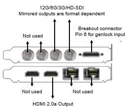
MRD 7000 – User Manual

       3.3.13         SNMP Trap Manager .......................................................................................................... 54
       3.3.14         Updating the MRD 7000 ..................................................................................................... 54
           3.3.14.1       Applying Software Updates ........................................................................................................... 54
           3.3.14.2       Rollback Software Updates ........................................................................................................... 55
      3.3.15    Reboot Unit ........................................................................................................................ 56
      3.3.16    Reset Defaults .................................................................................................................... 56
      3.3.17    Configuring ASI/SDI Ports and SDI Quad Link Mode .......................................................... 57
      3.3.18    Configuring Multichannel Decoder Outputs ....................................................................... 57
   3.4     REPORTING PANEL ........................................................................................................................... 59
      3.4.1 Active Alarms .......................................................................................................................... 59
      3.4.2 Event Logs ............................................................................................................................... 60
      3.4.3 Configuring the Logs ............................................................................................................... 61
   3.5     ABOUT PANEL ................................................................................................................................. 62
SECTION 4 APPENDICES.......................................................................................................................... 63
APPENDIX A            – ACRONYMS AND GLOSSARY ....................................................................................... 64
APPENDIX B            – ERROR AND EVENT LIST .............................................................................................. 65
APPENDIX C            – SPECIFICATIONS ......................................................................................................... 66
APPENDIX D            – DOWNMIX AUDIO SETUP ........................................................................................... 72
APPENDIX E            – DISCRETE AUDIO ........................................................................................................ 74
APPENDIX F            – OPEN SOURCE SOFTWARE.......................................................................................... 74
APPENDIX G            – WARRANTY ................................................................................................................ 76
APPENDIX H            – SUPPORT AND CONTACT INFORMATION ................................................................... 76

Page 8 (77)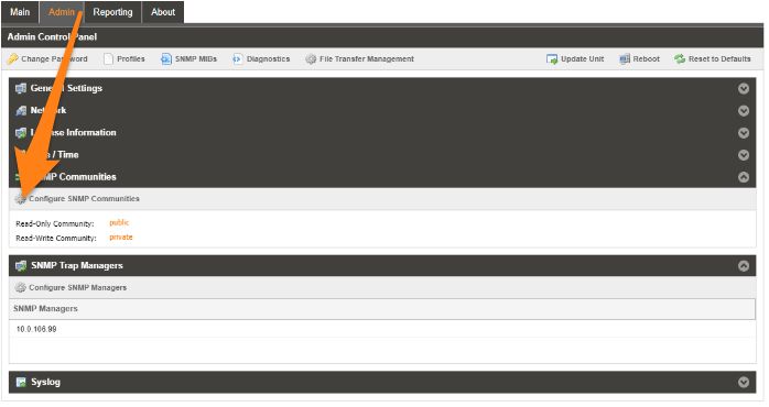
MRD 7000 – User Manual

                           Section 1 Overview

Introduction
   This section includes the following topics:
  1.1    PRODUCT INTRODUCTION .................................................................................................................. 10
  1.2    FRONT PANEL OVERVIEW .................................................................................................................. 11
  1.3    REAR PANEL OVERVIEW .................................................................................................................... 11

Page 9 (77)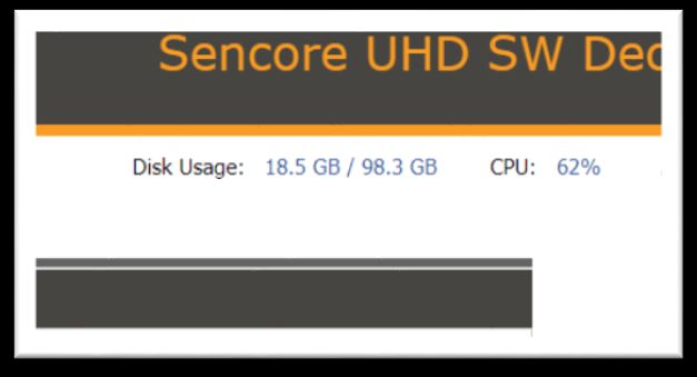
MRD 7000 – User Manual
1.1 Product Introduction
The new MRD 7000 is designed to be agile, supporting new codecs and video formats
through software-based updates versus traditional fixed ASIC hardware design.
The MRD 7000 maintains Sencore’s long tradition of ease of use, with a straight-forward
web interface accessible via all major browsers and complete control of the unit.
Support video codecs included HEVC, H.264, MPEG2 and JPEG2000.
Output resolutions and formats include 4K and HD applications with 12G-SDI, 6G-SDI,
Quad 3G-SDI, 3G-SDI, HDMI 2.0a and SMPTE 2110 support.
Every MRD 7000 ships with the software suite pre-loaded on appropriate hardware.
There are optional output configurations that will change the physical connectors
available on the back of the chassis.
Input Capabilites:
4x ASI
2x RJ45 GigE Ethernet Ports
UDP/RTP MPEG-IP Transport Streams
Unicast
Multicast
SMPTE 2022-7 hitless switching
FEC
SRT Input
File Input Playback
.ts and .trp transport stream files
Supported Codecs:
HEVC/H.265
MPEG-4/H.264
MPEG-2
JPEG 2000
Output Options:
HDMI 2.0 up to 4Kp60
QUAD 3G-SDI for UHD outputs
Single-Link
o HD-SDI up to 1080i59.94
o 3G-SDI up to 1080p60
o 12G-SDI up to 4Kp60
SMPTE 2110
o Dual 25GB SFP28 up to 4Kp60
o Dual 10GB SFP up to 1080p60
o Redundant outputs for hitless switching of downstream devices
Power Supply:
120/240V Switching Power Supplies
Redundant power design utilizing two independent cables
Page 10 (77)MRD 7000 – User Manual
1.2 Front Panel Overview
The MRD 7000 product is a software-based solution; designed to run on a PC server
chassis. Initial network configuration is done with keyboard, monitor, and mouse. Once
the IP is configured all operation and setup is via web-interface over a network.
To obtain the associated documentation from the server manufacturer or detailed
information regarding front of chassis indicator lights email ProCare@Sencore.com
1.3 Rear Panel Overview
The MRD 7000 server has multiple options for the backplane configuration. Both options
include dual network ports on the motherboard. Either port can be used to access the
web-interface or send and receive MPEG/IP.
For QUAD-3G (4x BNC cables to carry one video format such as 4K)
3 2 1
9 4
8 6 7 35 4
3
4
4
3
3
1. Breakout connector used for Genlock Input (requires breakout cable)
2. Top-left quadrant in Quad Link Mode or
12G/6G/3G/HD-SDI w/ audio in Single Link Mode
3. Top-right quadrant of 4K image (or single link copy w/out audio)
4. Bottom-left quadrant of 4K image (or single link copy w/out audio)
5. Bottom-right quadrant of 4K image (or single link copy w/out audio)
6. Eth0: One of two available RJ45 Ethernet ports for management or MPEG/IP
7. Eth1: One of two available RJ45 Ethernet ports for management or MPEG/IP
8. Local monitor output uses VGA (D-SUB) connector
9. Redundant power supplies (120/240 AC Switching PS)
VGA and keyboard are only used for setting the network configuration; operation of the device is performed through the web interface
For Single-Link SDI and HDMI 2.0 4K Playback
2 1
1
5 6 4 3
1. Breakout connector used for Genlock Input (requires breakout cable)
2. 2x BNC ports for mirrored 12G/6G/3G/HD-SDI w/ embedded audio
3. HDMI 2.0 for up to 4K resolutions
4. Eth0: One of two available RJ45 Ethernet ports for management or MPEG/IP
5. Eth1: One of two available RJ45 Ethernet ports for management or MPEG/IP
6. Local monitor output uses VGA (D-SUB) connector
7. Redundant power supplies (120/240 AC Switching PS)
VGA and keyboard are only used for setting the network configuration; operation of the device is performed through the web interface
Page 11 (77)MRD 7000 – User Manual
For SMPTE 2110 Playback
6
5 3 2 1
1. Data Path A: One of two SFP ports for SMPTE 2110 uncompressed video over IP
2. Data Path B: One of two SFP ports for SMPTE 2110 uncompressed video over IP
3. Eth0: One of two available RJ45 Ethernet ports for management or MPEG/IP
4. Eth1: One of two available RJ45 Ethernet ports for management or MPEG/IP
5. Local monitor output uses VGA (D-SUB) connector
6. Redundant power supplies (120/240 AC Switching PS)
VGA and keyboard are only used for setting the network configuration; operation of the device is performed through the web interface
For 12-G SDI and HDMI 2.0b Playback
1. SDI port 1 for 12G HD-SDI w/ embedded audio
2. SDI port 2 for 12G HD-SDI w/ embedded audio
3. Bi-level and tri-level genlock input port
4. Eth0: One of two available RJ45 Ethernet ports for management or MPEG/IP
5. Eth1: One of two available RJ45 Ethernet ports for management or MPEG/IP
6. Local monitor output uses VGA (D-SUB) connector
7. Redundant power supplies (120/240 AC Switching PS)
VGA and keyboard are only used for setting the network configuration; operation of the device is performed through the web interface
For Quad 3-G SDI Playback and Genlock
4
1. ASI or SD/HD/3G-SDI w/ embedded audio. Quadrants labeled 1 through 4
2. Bi-level and tri-level genlock input port
3. Eth0: One of two available RJ45 Ethernet ports for management of MPEG/IP
4. Eth1: One of two available RJ45 Ethernet ports for management or MPEG/IP
5. Local monitor output uses VGA (D-SUB) connector
6. Redundant power supplies (120/240 AC Switching PS)
Page 12 (77)MRD 7000 – User Manual
For Decoding 4xASI Input
1
4
1. 4x ASI input ports. ASI ports labeled 1 through 4
2. Local monitor output uses VHA (D-SUB) connector
3. Eth0: One of two availabler RJ45 Ethernet Ports for management of MPEG/IP
4. Eth1: One of two available RJ45 Ethernet ports for management or MPEG/IP
5. Redundant power supplies (120/240 AC Switching PS)
VGA and keyboard are only used for setting the network configuration; operation of the device is performed through the web interface
Page 13 (77)MRD 7000 – User Manual
Section 2 Installation
Introduction
This section includes the following topics:
2.1 RACK INSTALLATION ......................................................................................................................... 15
2.2 AC DUAL REDUNDANT POWER CONNECTIONS....................................................................................... 15
2.3 MAINTENANCE ................................................................................................................................ 15
2.4 NETWORK SETUP VIA KVM ............................................................................................................... 15
Page 14 (77)MRD 7000 – User Manual
2.1 Rack Installation
The MRD 7000 software product runs on Supermicro brand hardware. Please
consult the Supermicro 1028R-WMR(T) Revision 1.0b user manual for complete
detail on the rack installation and power cable connections.
https://www.supermicro.com/manuals/superserver/1U/MNL-1723.pdf
2.2 AC Dual Redundant Power Connections
The Dual Redundant option allows the MRD to be powered by two separate supplies
either operating 120V or 240V systems. The power supply will automatically detect the
system it is connected to. To hook up the power use the following steps:
1. Locate the AC power cords that are included.
2. Plug the female end of the power cords (end with no prongs) into the back of the unit.
3. Locate a protected outlet (usually inside of the rack) to plug the male ends of the power
cables into.
2.3 Maintenance
Refer to the server manufacturer documentation for detailed information regarding
server hardware maintenance.
To request a copy of the latest MRD software or release notes from Sencore email
ProCare@Sencore.com
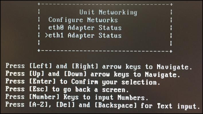
2.4 Network Setup via KVM
Connect the VGA (D-SUB) cable to a monitor and a USB keyboard.
The VGA will display the current ethernet settings and provide a text-based menu to
configure IP addressing, Subnet Mask, Gateway, and DNS settings.
Sencore recommends configuring the Eth0 port (Leftmost NIC when facing the rear of
the unit) be set to a static IP for web-interface access. Ensure the user machine is also
on the same network.
For additional information on initial network configuration menu see the Sencore MRD
7000 Quick-Guide documentation.
Page 15 (77)MRD 7000 – User Manual Section 3 Web-Interface Operation Introduction This section includes the following topics: 3.1 MRD 7000 WEB INTERFACE OVERVIEW.............................................................................................. 17 3.2 DECODER PANEL .............................................................................................................................. 18 3.3 ADMIN PANEL ................................................................................................................................. 45 3.4 REPORTING PANEL ........................................................................................................................... 59 3.5 ABOUT PANEL ................................................................................................................................. 62 Page 16 (77)
MRD 7000 – User Manual
3.1 MRD 7000 Web Interface Overview
3.1.1 Logging into the MRD Web Interface
To open the MRD 70000 web interface use one of the following supported browsers and
navigate to the unit’s IP address:
Internet Explorer 7 & above
Firefox 3.5 & above
Google Chrome
Microsoft Edge
The user will need to login to the web interface. By default, the admin user account is
available without a password. Press the login button in order to login to the web
interface.
Default Credentials
Username: admin
Password: (none / leave blank)
3.1.2 Hiding Unused Inputs
The MRD 7000 web interface allows the user to hide inactive inputs using the
button or show all available inputs by click the button. Only the
selected input will be displayed when unused inputs are hidden.
3.1.3 Buttons and Status Indicators
When the icon is shown user configuration is available. Clicking this button will open
configuration menus where settings can be changed by the user.
Page 17 (77)MRD 7000 – User Manual
When the icon is shown additional status information can be viewed. Click this button
will expand the menu to display the additional status information. All text in status menus
shown in ORANGE are user configurable settings. Text shown in BLUE is not user
configurable and is strictly a status or value. To minimize the status windows again click
the icon.
Status in the MRD 7000 web interface is shown with LED status indicators:
Status is good. No errors are present and function is operating
Green LED
normally.
Status indicates function is affected by active error. To view
Red LED
the errors, navigate to Alarms panel to view Active Errors.
Status is inactive. Function is currently disabled or
Grey LED
unavailable.
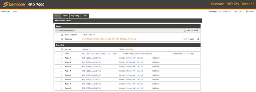
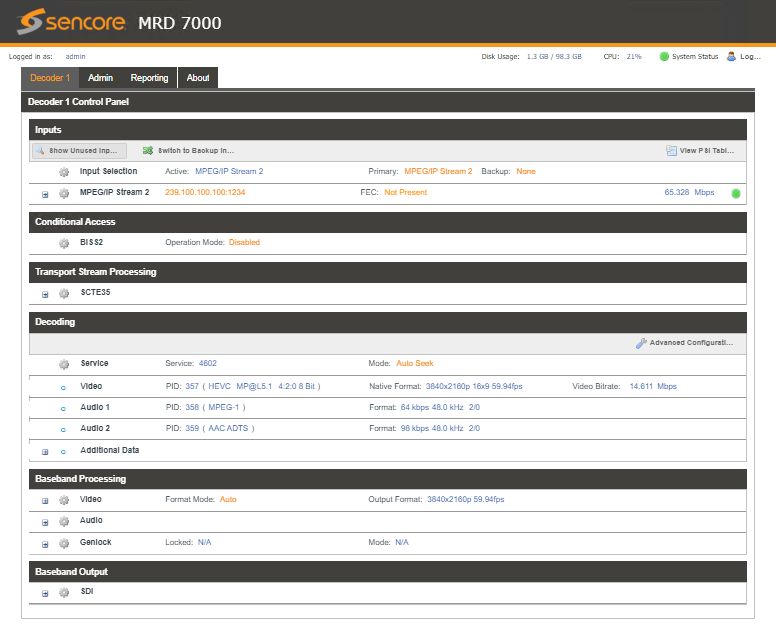
3.2 Decoder Panel
The Decoder panel of the MRD 7000 web interface is used to configure the unit to
decode and what output format to use. Each functional piece has a heading: Inputs,
Conditional Access, Transport Stream Processing, Decoding, Baseband Processing and
Baseband Output sections are listed from the top down.
Page 18 (77)MRD 7000 – User Manual 3.2.1 Configuring Active Input This menu allows the user to configure a primary and backup input. In case there is an input failover the MRD 7000 is capable of detecting the failed state and switching to a secondary backup input in order to provide a continuous output. Which input is primary and backup, how the inputs switchover and restore and switchover timing is all user configurable. Input options include MPEG/IP Stream 1, MPEG/IP Stream 2, Input File, SRT Input 1, SRT Input 2, Seamless RTP stream Each MPEG/IP Stream Input, SRT Stream Input and Seamless RTP Stream can be configured to use either Eth0 or Eth1 ports on the back of the chassis. Input File can play a stored .TS or .TRP transport stream file by uploading to the MRD 7000 internal storage. This is done by browsing to the MRD’s IP address using FTP or Windows file sharing. Page 19 (77)
MRD 7000 – User Manual

                     Active Input and Failover Configuration Menu
 Setting         Range                       Description
 Primary Input   MPEG/IP Stream 1            Used for both normal operation and input
                                             failover settings. During normal operation
                 MPEG/IP Stream 2
                                             this input will be the active input.
                 Input File
                 ASI Port 1-4
                 SRT Input 1
                 SRT Input 2
                 Seamless RTP Stream
                 None
 Backup Input    MPEG/IP Stream 1            During failover operation this input will
                                             become the active input. The catalyst for
                 MPEG/IP Stream 2
                                             what causes the unit to switch to this input
                 Input File                  is configured in the following setting.
                 ASI Port 1-4
                 SRT Input 1
                 SRT Input 2
                 Seamless RTP Stream
                 None
 Switch On       Manual Only                 Manual Only: the unit will not switch inputs
                                             automatically. The user must manually
                 TS Sync Loss
                                             switch inputs.
                 Decode Failure
                                             TS Sync Loss: the MRD 5800 will switch
                                             from the primary to the backup input if the
                                             primary stream loses synchronization for
                                             the duration of the Switchover Interval.

Page 20 (77)
MRD 7000 – User Manual
Decode Failure: the unit will switch to the
backup input when it encounters decoding
errors on the primary input.
Restore On Manual Only Manual Only: the unit will not restore to the
primary input automatically. The user must
Primary Input TS Restored
manually switch inputs.
Backup Input TS Sync Loss
Primary Input TS Restored: the MRD 5800
Decode Failure restores to primary when the Primary input
regains transport stream synchronization.
Backup Input TS Sync Loss: the unit will
switch from backup to primary when the
backup stream loses synchronization for the
duration of the Switchover interval.
Decode Failure: the unit restores to the
Primary Input when the Backup Input
experiences a decoding error.
Switchover 1-20 seconds The time in seconds which Switch On or
Restore On value must remain in the
configured state before the MRD 5800
switches between the Primary Input and
Backup Input or vice versa.
Page 21 (77)MRD 7000 – User Manual
3.2.1.1 Configuring MPEG/IP Inputs
When either MPEG/IP streams are selected as the active input click on the IP address
and gear icon should be visible. Clicking on the gear allows the user to configure the
desired input port and network destination parameters.
Setting Range Description
Receive Enabled This setting allows the user to enable or
disable these input stream settings.
Disabled
Physical Eth0 The physical connector on the MPEG/IP
Connector card that will be used to receive the input.
Eth1
Mode Multicast Multicast setting allows the unit to receive
multicast streams. Multicast streams
Unicast
originate from the IP range 224.0.0.0 –
239.255.255.255. Unicast allows the unit to
receive unicast streams. Unicast streams
originate directly from a source device.
Destination IP 224.0.0.0 – This setting is only available when receiving
239.255.255.255 a multicast stream. This address is the IP
address the source device is receiving
from.
Destination Port 0 - 65535 This is the UDP port the source device is
receiving from. This is the only setting
required to receive a unicast stream.
Page 22 (77)MRD 7000 – User Manual
FEC Disabled Enabling FEC (Forward Error Correction)
Enabled tells the MRD 7000 to look at Destination
Port +2 and Destination Port +4 for a
SMPTE 2022 FEC Matrix.
IGMP Filter Mode Exclude Used on networks supporting IGMPv3. If
this setting is set to Exclude any streams
Include
originating from the user defined IP
addresses will be rejected. If this setting is
set to Include any streams originating from
the user defined IP addresses will be
received.
Once the MRD is locked on an MPEG/IP signal the indicator light on the right will turn
green, and the received bitrate is displayed. Sync status, the number of transport stream
packets inside the UDP payload, and encapsulation type are shown under Status.
Statistics are displayed representing Out of Order Packets, Duplicate Packets, Lost
Packets and Discontinuity in RTP IP streams. These counters can be manual reset
using the Reset Counters button. The last reset of these error counters is displayed in a
date/time format.
The MRD 7000 can also display the individual PID values and Program/Service numbers
by clicking on the View PSI Tables hyperlink.
Page 23 (77)MRD 7000 – User Manual 3.2.1.2 Configuring File Input When File Input is selected as the active input, clicking on the gear icon allows the user to choose source file. After Input File has been chosen user has a possibility to: Play Stop Set Start / Stop End Points. Page 24 (77)
MRD 7000 – User Manual

Once the File Input is played out the indicator light on the right will turn green, and the
progress bar will be activated

The MRD 7000 can also display the individual PID values and Program/Service
numbers by clicking on the View PSI Tables hyperlink.

Page 25 (77)
MRD 7000 – User Manual

3.2.1.3        Configuring ASI Input
When ASI Input is selected as the active input, clicking on the gear icon allows the user
to enable/diable ASI port.

Once the MRD is locked on ASI signal the indicator light on the right will turn green, and
the received bitrate is displayed.

The MRD 7000 can also display the individual PID values and Program/Service
numbers by clicking on the View PSI Tables hyperlink.

Page 26 (77)
MRD 7000 – User Manual

3.2.1.4        Configuring SRT Input
When SRT Input is selected as the active input, clicking on the gear icon allows the user
to configure SRT dialog.

 Setting             Range                      Description
 Receive             Enabled                    This setting allows the user to enable or
                                                disable these input stream settings.
                     Disabled
 Physical            Eth0                       The physical connector on the MPEG/IP
 Connector                                      card that will be used to receive the input.
                     Eth1
 Call Mode           Caller, Listener,          Defines the ‘handshake’ mechanism to be
                     Rendezvous                 used when establishing connection
 Remote IP           xxx.xxx.xxx.xxx            Defines the IP address of the stream on the
                                                remote device
 Remote Port         1 - 65535                  Defines the port of the stream on the
                                                remote device
 Local Port Mode     Auto, Manual               In Auto Mode the local port number will be
                                                assigned
                                                In Manual Mode the local port number will
                                                be defined by the user

Page 27 (77)
MRD 7000 – User Manual Local Port 1 – 65535 Defines the local port number Discovery 1 – 100, use 0 for infinite Defines the length of time to wait for the Timeout stream to be discovered (seconds) Passphrase 10 – 79 characters Defines the encryption passphrase Latency (ms) 1 - 8000 Defines buffer size in milliseconds Once the MRD is locked on an SRT signal the indicator light on the right will turn green, and the received bitrate is displayed. Connection state, up time, local port, encryption mode, decryption state, Round Trip Time, Buffer Size, Latency and Link Bandwidth are shown under Status. Statistics are displayed representing number of Reconnections, number of Received Packets, amount of Received Bytes, number of Lost Packets, amount of Lost Bytes, number of Skipped Packets and amount of Skipped Bytes. These counters can be manual reset using the Reset Counters button. The last reset of these error counters is displayed in a date/time format. The MRD 7000 can also display the individual PID values and Program/Service numbers by clicking on the View PSI Tables hyperlink. Page 28 (77)
MRD 7000 – User Manual

3.2.1.5           Configuring RTP Seamless Input (SMPTE 2022-7)
When RTP Seamless Input is selected as the active input, clicking on the gear icon
allows the user to configure RTP Seamless dialog.

 Setting              Range                    Description
 Receive              Enabled                  This setting allows the user to enable or
                                               disable these input stream settings.
                      Disabled
 Physical             Eth0                     The physical connector on the MPEG/IP
 Connector                                     card that will be used to receive the input.
                      Eth1
 Destination IP       224.0.0.0 –              This address is the IP address the source
                      239.255.255.255          device is receiving from.
 Destination Port     0 - 65535                This is the UDP port the source device is
                                               receiving from.
 IGMP Filter Mode     Exclude                  Used on networks supporting IGMPv3. If
                                               this setting is set to Exclude any streams
                      Include
                                               originating from the user defined IP
                                               addresses will be rejected. If this setting is
                                               set to Include any streams originating from
                                               the user defined IP addresses will be
                                               received.

Page 29 (77)
MRD 7000 – User Manual Once the MRD is locked on an RTP Seamless signals the indicator light on the right will turn green, and the received bitrate is displayed. Sync status, number of active paths, the number of transport stream packets inside the UDP payload, and encapsulation type are shown under Status. For both paths statistics are displayed representing Out of Order Packets, Duplicate Packets, Lost Packets and Discontinuity in RTP IP streams. These counters can be manual reset using the Reset Counters button. The last reset of these error counters is displayed in a date/time format. The MRD 7000 can also display the individual PID values and Program/Service numbers by clicking on the View PSI Tables hyperlink. Page 30 (77)
MRD 7000 – User Manual

3.2.2      Configuring Conditinal Access (BISS2 descrambling)
This menu allows the user to configure BISS descrambling. 12 unique BISS keys can be
entered. Clicking on the gear icon allows the user to configure BISS2 dialog

 Setting            Range                     Description
 Operation Mode     Enabled                   Enable / Disable BISS descrambling
                    Disabled
 Select Key         Key 1 - 12                Select a key to configure
 Alias              16 characters             Set an Alias for the selected key
 Mode               Mode 1                    This setting sets the Mode of the BISS key
                    Mode E                    that has scrambled the transport stream.
 Mode 1 Session     N/A                       If Mode 1 is selected the user enters the
 Word                                         BISS session word here.
 Mode E Session     N/A                       If Mode E is selected the user enters the
 Word                                         BISS session word here
 Mode E Injected    N/A                       If Mode E is selected the user enters the
 ID                                           BISS injected ID here.

Page 31 (77)
MRD 7000 – User Manual
3.2.3 Configuring Transport Stream Processing
Setting Heartbeat timeout will determine the time in minutes between SCTE35
messages before the MRD 5800 will report an error. Timeout can be configured in the
following way:
3.2.4 Configuring Decoding and Service Selection
This menu allows the user to configure which service the MRD 7000 will decode. There
are two editable fields in this menu.
Setting Range Description
Mode Auto Seek The MRD will decode the first service found
Service Lock Locks the decoder to defined service
number
Service Number # Click the drop-down to select a service
number . This list will be populated by all
services in the incoming transport stream.
Page 32 (77)MRD 7000 – User Manual When the MRD 7000 begins decoding a service, the Additional Data status will report HDR metadata, SMPTE 2038, Closed Captions, SCTE35 and Subtitles presence. 3.2.4.1 Advanced Configuration This section allows the user to configure advanced settings of the MRD 7000. Parallel Frame Processing allows the user to tune the decode latency of the MRD 7000. Lower Parallel Frames results in lower latency. Setting these values too low can result in dropped video frames. Default settings are recommended unless minimal latency is crucial to the application. Clicking the Restore Defaults button will reset all values to the default values. Page 33 (77)
MRD 7000 – User Manual

 Setting             Range                    Description
 MPEG2               1-50                     This setting changes the parallel frames
                                              processed when decoding MPEG2 video.
 H264                1-50                     This setting changes the parallel frames
                                              processed when decoding H264 video.
 HEVC                1-50                     This setting changes the parallel frames
                                              processed when decoding HEVC video.
 JPEG2000            1-50                     This setting changes the parallel frames
                                              processed when decoding JPEG2000
                                              video.
 Preview State       Enabled/Disabled         This section allows the user to view a
                                              thumbnail preview of the video being
                                              decode by the MRD 7000. Enabling the
                                              Preview State will cause the MRD 7000
                                              to display a thumbnail in the Decoding
                                              section.

3.2.5            Configuring Baseband Processing
The section of the main tab allows the user to configure the video and audio baseband
processing.

Genlock status is reported as Locked/Unlocked (reference source enabled) or N/A
(refence source disabled) and Mode status.
On MRD 70150 module (Basic 12G-SDI and HDMI 2.0a Output Module) Genlock
reference input is automatically detected and applied by the MRD 7000.

Page 34 (77)
MRD 7000 – User Manual On MRD 70130 (12G-SDI and HDMI 2.0b Output Module) and 70140 (Quad 3G-SDI Output Module) modules with the “Reference Source” configured as External, the Genlock Format must be manually defined in order for the card to lock to the Genlock signal. In multi-channel decode applications, the same Genlock reference is used for all SDI outputs. MRD 70130: MRD 70140: Page 35 (77)
MRD 7000 – User Manual

When reference signal cannot be provided, internal signal should be activated instead.
On MRD 70130 (12G-SDI and HDMI 2.0b Output Module) and 70140 (Quad 3G-SDI
Output Module) modules internal Genlock reference input can be activated in
Admin->ASI/SDI module tab. Genlock output framerate should match output video
framerate.
MRD 70130:

MRD 70140:

Page 36 (77)
MRD 7000 – User Manual

3.2.5.1         Configuring Video Baseband Processing
The Configure Video menu is opened by clicking on the gear icon just under the
Baseband Processing section title.

 Setting             Range                    Description
 Format Mode         Auto                     The MRD will match output format to input
                     Manual                   MRD uses specified Manual Format value
 Manual Format       3840x2160p 60fps         Refer to Specification for complete list
                     1280x720p 59.94fps
 Raster Mode         Solid Color              Selected color outputs if no input is locked
                     Last Frame               Last decoded frame is shown when no input
 Raster Color        Black                    Choose color to display when raster mode
                                              is set to Solid Color
                     White
                     Yellow
                     Cyan
                     Magenta
                     Red
                     Blue
                     Green
                     Gray

Page 37 (77)
MRD 7000 – User Manual
3.2.5.2 Configuring Audio Baseband Processing
The audio menu allows the user to configure the audio processing mode (decode /
discrete) settings of the MRD 7000. Up to 8 audio PID’s inside of the decoded service
can be processed.
The configured settings are displayed when expanding the audio status by clicking the +
button.
Setting Range Description
Operational Mode Line Mode Refer to Appendix E for explanation.
RF Mode
Custom 1
Custom 0
Processing Mode Downmix Refer to Appendix D for explanation.
Discrete Refer to Appendix E for explanation
Dynamic Range Enabled Use dynamic range for AC-3 downmix
Disabled
Downmix Lo/Ro (Stereo) When the audio is downmixed in the MRD
7000 two audio channels are created. The
Page 38 (77)MRD 7000 – User Manual
Lt/Rt (Dolby Surround) channels can be configured using the
settings available in the drop-down menu..
Lt/Rt (Auto)
(Refer to Appendix E)
Dual Mono
Dual Left
Dual Right
3.2.5.3 Configuring Genlock Processing
The Genlock menu allows the user to configure Horizontal Offset Pixels. The configure
menu is opened by clicking on the gear icon.
Page 39 (77)MRD 7000 – User Manual
3.2.6 Configuring Baseband Output
This menu allows the user to configure the SDI output settings for the MRD 70130, MRD
70140 and MRD 70150 modules.
3.2.6.1 Configuring SDI video
The MRD 7000 comes with the ability to decode SDI Level A or SDI Level B. The MRD
70140 module has an option to select Two Sample Interleave or Square Division for the
SDI Link Mode when it’s configured for UHD (SDI Quad Link Mode -> Enabled). Picture
below displays how SDI video can be configured depends on output module.
Setting Range Description
Level A or B This setting changes the SDI output level.
Link Mode Two Sample Interleave This setting changes the SDI link mode.
Square Division
Page 40 (77)MRD 7000 – User Manual 3.2.6.2 Configuring SDI Audio This menu allows the user to configure the SDI embedded audio settings. The MRD 7000 comes standard with the ability to handle up to eight audio services. Eight audio pairs can be embedded into four Group Pairs. Each Group Pair can contain a PCM (either downmixed or discrete decode) or passthrough audio (Dolby E, Dolby ATMOS). In the case where a discrete audio pair is being embedded, the channel pair in the column must be selected. For audio services that indicate the specific channels (Lf, Rf, C, Ls, Rs, LFE) the user can select the audio channels to assign to a output using the named discrete options. The following audio formats identify specific channels: Dolby Digital, Dolby Digital Plus, AAC-LC, HE-AAC. If the specific channels are not identified (LPCM Audio for example) than the user can use the multi-channel audio service to select the channel pair of the audio service to output. When the user has selected a named discrete option but the audio channels are not identified in the service the unit will output Ch1/Ch2 (if present) if Lf/Rf is chosen, Ch3/Ch4 (if present) if C/LFE is chosen and Ch5/Ch6 (if present) if Ls/Rs is chosen. Advanced Audio embedding allows to embed mono audio channels from multiple audio PIDs in the same group/pair, i.e. a user can use mono audio left from audio PID 1 and mono audio right from audio PID 2 and embed them as Group 1 Pair 1. Page 41 (77)
MRD 7000 – User Manual

3.2.6.3        Configuring SDI ANC

The Configure SDI menu also allows for the ability to enable or disable ANC data.

Page 42 (77)
MRD 7000 – User Manual

 Setting             Range                    Description
 SMPTE2108           Enabled                  This setting enabled SMPTE 2038
                                              embedding on a selected line.
                     Disabled
 Closed Captions     Enabled                  This setting enables Closed Captions
                                              embedding on a selected line.
                     Disabled
 SMPTE2038           Enabled                  This setting enables SMPTE 2038
                                              embedding
                     Disabled
 VPID                Enabled                  This setting enables VPID embedding on a
                                              selected line
                     Disabled
 SCTE104             Enabled                  This setting enables SCTE104 embedding
                                              on a selected line
                     Disabled
 OP47                Enabled                  This setting enables OP47 embedding on a
                                              selected line
                     Disabled
 SMPTE2031           Enabled                  This setting enables SMPTE2031
                                              embedding on a selected line
                     Disabled

SMPTE 2038 VANC Embedding
The MRD 7000 supports extraction of SMPTE 2038 metadata from the input video PID
and embedding in SDI. User configuration is needed for enabling SMPTE 2038 data to
be embedded in SDI. Presence of the incoming SMPTE 2038 data is reported in the
Additional Data status in the Decoding section.
SMPTE 2108 VANC Embedding
The MRD 7000 supports extraction of SMPTE 2108 metadata from the input video PID
and embedding in SDI. User configuration is needed for enabling SMPTE 2038 data to
be embedded in SDI. Presence of the incoming SMPTE 2108 data is reported in the
Additional Data status in the Decoding section (Transfer Characteristics).
SCTE35/104 VANC Embedding
The MRD 7000 extracts SCTE 35 messages from the transport stream then converts
them to SCTE104 messages, and embeds them as VANC packets on the SDI output.
User configuration is needed for enabling SCTE104 data to be embedded in SDI.
Presence of the incoming SCTE35 data is reported in the Additional Data status in the
Decoding section.
OP47 VANC Embedding
The MRD 7000 supports extraction of OP47 subtitles (UHD/HD) from the input PID and
embedding in SDI. User configuration is needed for enabling OP47 data to be
embedded in SDI. Presence of the incoming OP47 data is reported in the Additional
Data status in the Decoding section

Page 43 (77)
MRD 7000 – User Manual
SMPTE2031 VANC Embedding
The MRD 7000 supports extraction of SMPTE2031 subtitles (SD only) from the input
PID and embedding in SDI. User configuration is needed for enabling SMPTE2031 data
to be embedded in SDI. Presence of the incoming SMPTE2031 data is reported in the
Additional Data status in the Decoding section
3.2.7 Configuring SMPTE 2110
This menu allows the user to configure the SMPTE 2110 output settings. The MRD 7000
comes with the ability to configure two separate paths for SMPTE 2110. Also with
SMPTE 2110 is the ability to configure eight audio pairs. Audio, Video, and Data
Streams are all configurable to enable or disable the output, set Destination IP, and
Destination Port.
Setting Range Description
Output Enabled This setting allows the user to enable or
disable the output.
Disabled
Destination IP 224.0.0.0 - This setting allows a user to configure the
output destination IP address.
239.255.255.255
Destination Port 0-65535 This is the UDP port the source device is
sending to.
Page 44 (77)MRD 7000 – User Manual 3.3 Admin Panel To access the Admin Control Panel, click on the Admin tab. This menu allows the user to control many global settings and maintenance tasks on the MRD 7000. 3.3.1 File Transfer Management The File Transfer Management configuration button opens up a menu in which you can enable or disable authentication for uploading pre-recorded media files. Page 45 (77)
MRD 7000 – User Manual

 Setting              Range                    Description
 Allow Anonymous      Enabled                  Anyone can upload or download media
                      Disabled                 Requires username and password to
                                               access
 Username             Alpha-Numeric Entry      User-defined user name for access the
                                               media storage

 Password             Alpha-Numeric Entry      User-defined password for accessing the
                                               media storage

3.3.2       Disk Usage Statistics
The current available and used disk space of the server is shown throughout the user-
interface on the top right corner of the page

Page 46 (77)
MRD 7000 – User Manual 3.3.3 Unit Alias The Unit Alias allows a unique name or description to be entered which shows on the web-interface title pane. This is configured inside the Admin page. 3.3.4 Changing Unit Password The MRD can be assigned an access password and the current access password can be changed. In order to make changes to passwords, click the change password button. A window will appear to enter the current password and new password. Note: the username for MRD web-login is always admin 3.3.5 Profiles The MRD 7000 has the ability to save all configured settings to multiple profiles. Profiles can be saved locally, renamed and saved to external storage to be used on other MRD 7000s. Profiles can be used to quickly and easily change the configuration of an MRD to suit different inputs and decoding requirements. Page 47 (77)
MRD 7000 – User Manual
Action Button Description
Add New Profile Adds a new profile from current settings. User
must name profile before creation is complete.
Upload Profile Allows the user to browse to external storage or
workstation to upload profile to MRD.
Apply Profile Select a profile from the drop-down menu and
click this button. The MRD will apply all settings
contained in the profile selected.
Rename Profile Select a profile from the drop-down menu and
click this button. The user will be prompted for a
new name for the profile.
Delete Profile Select a profile from the drop-down menu and
click this button. The user will be prompted to
confirm deletion of the profile.
Download Profile Select a profile from the drop-down menu and
click this button. The user will be prompted to
select a directory to download the profile.
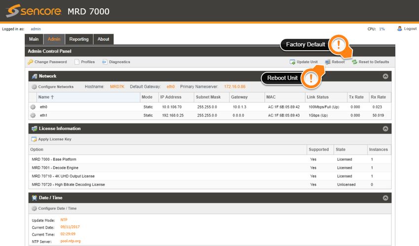
3.3.6 Configure Unit Networks
The MRD 7000 can be assigned a Hostname and DNS servers. To access this menu,
click on the Configure Networks gear icon in the Admin page.
The Default Gateway of the web-interface can also be pointed at a chosen network port
(Eth0 or Eth1). The web-interface is accessible from the IP address of either Ethernet
port; however, be sure to configure the two ports for separate subnets.
Page 48 (77)MRD 7000 – User Manual
Setting Range Description
Network Name Alphanumeric, no This setting allows the user to define an optional
spaces allowed unit Hostname.
Mode Static IP is entered by user and will not change
DHCP IP is assigned to MRD by network/router
IP Address Four decimal octets: This option is only available if Static Mode is set.
This is the IP address assigned to the
XXX.XXX.XXX.XXX
management port.
Subnet Mask 255.0.0.0 – This option is only available if Static Mode is set.
255.255.255.254 This is the Subnet Mask assigned to the
management port.
Gateway Four decimal octets: This option is only available if Static Mode is set.
This is the Gateway address assigned to the
XXX.XXX.XXX.XXX
management port.
Page 49 (77)MRD 7000 – User Manual
3.3.7 Configure SMPTE 2110 Video/IP Networks
With the SMPTE 2110 module, a user can configure the Video/IP Redundancy Mode. To
access this menu, click on the Configure gear icon under the Video/IP Network Module 1
section in the Admin page.
The PTP Master Domain can also be adjusted to synchronize the grand master PTP
clock.
Setting Range Description
IP Address Four decimal octets: This is the IP address assigned to the SFP port
on the selected SMPTE 2110 port.
XXX.XXX.XXX.XXX
Subnet Mask 255.0.0.0 – This is the Subnet Mask assigned to the SFP port
255.255.255.254 on the selected SMPTE 2110 port.
Gateway Four decimal octets: This is the Gateway address assigned to the SFP
port on the selected SMPTE 2110 port.
XXX.XXX.XXX.XXX
3.3.8 Software Support Agreements
Purchase of the MRD 7000 software includes one year of software support. This
provides access to the latest software versions throughout that one-year period. These
software versions include:
Bug fixes
General updates
Maintenance releases
The MRD 7000 will only accept software updates which were released during the active
SSA period. Software updates released following the expiration of the SSA will be
rejected on upload, until the product’s SSA has been re-activated. The actual SSA
information is maintained on the product itself and can be updated by applying a license
key via the web user interface. The product’s user interface displays the end date to
Page 50 (77)MRD 7000 – User Manual ensure the user is always informed of their SSA status. Regardless of the status of the software subscription agreement, Sencore offers phone and email technical support during regular business hours for all products. Once the SSA period has expired, customers are free to keep using the software version they already have or other versions from before the expiration date but applying newer versions will require an extended SSA. 3.3.9 Licensing Certain features of the MRD require licenses in order to be functional. The interface displays all licenses available as well as the following status: License Locked or Unlocked License is Supported or Unsupported by the installed hardware If licenses need to be applied to the MRD click Apply License Key button. The menu below will appear where the user can copy and paste the provided license key from Sencore. Page 51 (77)
You can also read