In-Space Robotic Assembly of Large Telescopes
←
→
Page content transcription
If your browser does not render page correctly, please read the page content below
In-Space Robotic Assembly of Large Telescopes

Máximo A. Roa1 , Korbinian Nottensteiner1 , Gerhard Grunwald1 , Pablo Lopez Negro2 , Aurelian Cuffolo2 ,
         Sabrina Andiappane2 , Mathieu Rognant3 , Antoine Verhaeghe4 , Vincent Bissonnette5
                        1 German Aerospace Center (DLR), 82234 Wessling, Germany
                                2 Thales Alenia Space, 06150 Cannes, France
                      3 ONERA - The French Aerospace Lab, 31055 Toulouse, France
                                    4 CSEM, 2002 Neuchatel, Switzerland
                             5 Magellium, 31520 Ramonville Saint-Agne, France

   Abstract— Advances in our understanding of the universe
have been enabled by ground and particularly by space-based
telescopes (e..g. the Hubble), free of interferences from Earth’s
atmosphere. However, current astronomical challenges in areas
such as exoplanets, interstellar medium and structure of the
universe, require larger telescope apertures. Using deployable
structures and a segmented primary mirror, such as in the
James Webb telescope, allows an increase of the aperture, but
the maximum size of the telescope is anyways limited mainly by
the fairing size of the launch vehicle. Further increasing the size
of the telescope requires a technological change, to move toward
space-based assembly using autonomous robotic systems. This
paper provides a survey of existing concepts for in-space
assembly of telescopes, and introduces PULSAR (Prototype of
an Ultra Large Structure Assembly Robot), the latest European
effort toward proving feasibility of the technologies required for
autonomous robotic assembly of a telescope or a large space-                Fig. 1. Hubble Space Telescope, in service since 1990 (Courtesy of NASA).
borne structure.

                        I. I NTRODUCTION
                                                                            fixed location on ground. Moreover, some studies require
   During the last few decades, astronomy has found an                      specific conditions that cannot be met with Earth-based
increasing interest upon the study of exoplanets. Finding                   telescopes, as part of the frequency spectrum is filtered by
new planets outside the solar system, understanding the                     the atmosphere, hiding information that is essential for the
physical properties of these planets and investigating the                  advancement of astronomical knowledge.
existence of an atmosphere (and its components) brings key                     Space-based telescopes complement the capabilities of
elements for scientists towards the final goal of understand-               large telescopes on Earth thanks to the larger range of
ing life formation and conditions for life existence beyond                 the electromagnetic spectrum that the telescope is able to
the Earth [1], and this scientific goal has continuously pushed             acquire [2], thus enabling observations without atmospheric
toward the development of larger telescopes. This research                  disturbance. The main features of a telescope are its collect-
topic, together with more classical investigations such as                  ing capabilities (mostly represented by the surface or diame-
the formation and structure of the universe, the interstellar               ter of its primary mirror, although some other elements such
medium, and the origins of the solar system, constitute hot                 as focal length are also important) and its pointing accuracy.
topics in astronomy nowadays. Such astronomical studies                     The instrument collection area, or aperture diameter, deter-
have been mostly done from Earth, initially using telescopes                mines the signal strength and the spatial resolution that can
with monolithic mirrors, and nowadays using segmented                       be achieved, while the pointing accuracy determines directly
telescopes that enhance the diameter of the primary mirror,                 the quality of the obtained image. The most iconic example
such as in the Thirty Meter Telescope (TMT)1 or the 39 m                    of space telescopes is the Hubble Telescope (HST, Fig. 1)3 ,
European Extremely Large Telescope (EELT)2 . However,                       launched in 1990 and still operating after 29 years of service.
these telescopes are fundamentally limited by the absortion                 The HST operates in Ultraviolet/optical/infrared (UVOIR)
and distortion created by the Earth’s atmosphere, and by their              wavelengths, providing high quality images that have enabled
                                                                            important advances in the scientific community. It is also
   This work was partially supported by the European Union’s Horizon 2020
research and innovation programme under grant agreement No. 821858,         famous because of the various servicing missions it required,
project PULSAR.                                                             performed with the Space Shuttle and with astronaut labor.
   1 https://www.tmt.org/
   2 https://www.eso.org/sci/facilities/eelt/                                 3 https://hubble.nasa.gov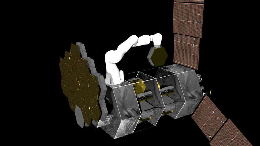
The successive missions to the HST constitute an example astronomical studies. Table I summarizes the main features
of servicing and on-orbit assembly (since several instruments of current and planned space telescopes.
were replaced and upgraded), which have allowed it to A different path for improving size of space telescopes is
achieve a lifetime much longer than expected. HST has a its assembly in space using (mostly autonomous) robotics,
2.4 m monolithic primary mirror. The largest space telescope which could bring additional versatility, and mass and size
using a single piece mirror up to now was the Herschel optimization. In this case, the primary mirror would be
Space Observatory4 , an infrared telescope with an aperture assembled in orbit instead of being folded for launch and
of 3.5 m. It was built and operated by ESA, and was active deployed when starting operation. Though in-space assembly
from 2009 till 2013. could be carried out by astronauts, as shown previously in
the repairing and servicing of the HST or the assembly of
the ISS, the process would be very expensive and time-
consuming due to the limited dexterity of the astronaut inside
a space suit and the large number of working hours that
would be required for such complex assembly operations. On
the other hand, technologies for robotic ground assembly are
currently under development, and initial demonstrations of
fully autonomous assembly have already been provided [5].
Current space telescopes are built and tested at 1 g condi-
tions, while their operations are performed in microgravity.
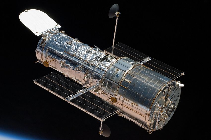
Fig. 2. Deployment of the James Webb Telescope (launch planned for Assembly of telescopes in space would alleviate the high
2021) (Courtesy of NASA).
constraints on design, manufacturing and testing required
to fulfill operations in both environments at the same time.
Though an increase in diameter for space telescopes is
The telescopes could then be designed for in-service loads
desirable, the maximum aperture of the telescope is limited
(0 g) rather than for testing loads (1 g). Also, launching the
by the physical size of the launch vehicle fairing, mass of the
telescope components (in a single or in multiple launches)
payload that can be accommodated on the launch vehicle,
implies that less mass is required to package the components
and overall cost (though the overall cost of a telescope is
so that they survive the accelerations during the launch
mainly limited by the justification of its scientific return).
phase (vibration, noise, shock levels). In order to improve
There are also challenges in achieving a large aperture while
competitiveness of this alternative, the use of a conventional
keeping a high mirror surface precision and stability with a
launcher is a key feature; otherwise the additional com-
single-piece primary mirror. New developments try to over-
plexity introduced by the robotic manipulators required for
come these limitations by using segmented mirrors supported
assembly is hardly justified. Note that the same rationale for
by a deployable structure, such that the telescopes can fit into
assembling space telescopes is valid for a starshade, i.e., a
the launcher fairing. The closest example is NASA’s James
spacecraft that could fly in formation with the space telescope
Webb Space Telescope (JWST, Fig. 2)5 , which has a primary
to block light from stars, thus allowing direct observation of
mirror of 6.5 m diameter composed by 18 hexagonal mirror
exoplanets.
segments [3]. The JWST is scheduled for launch in 2021 us-
This paper focuses specifically on the survey of existing
ing an Ariane 5 rocket, which has a fairing diameter of 5.4 m.
concepts for autonomous assembly of large telescopes in
The deployable structure increases the complexity of the
space. In general, the concepts include a modular deployable
mission, as the deployment relies on different mechanisms
structure, satellites flying in a coordinated fashion, or a
that must be actuated in the correct order without jamming
mission including a general purpose robot with advanced
(e.g. hinges, telescopic tubes). The next generation of space
autonomous assembly capabilities. Finally, the project PUL-
telescopes would need additional emerging technologies in
SAR (Prototype of an Ultra Large Structure Assembly
order to continue escalating the size of the primary mirror,
Robot) is introduced as the latest European effort to develop
as it can be considered that JWST has reached the limit of
and demonstrate the technology that will allow the on-orbit
what is feasible within a regular size launcher. For instance,
precise assembly of a very large primary mirror by an
LUVOIR-A is a planned space telescope with a segmented
autonomous robotic system.
primary mirror of 15 m diameter, significantly bigger than
any previous development [4]. NASA is aiming to increase II. OVERVIEW OF PROPOSED IN - SPACE TELESCOPE
the size of its next generation of space telescopes using the ROBOTIC ASSEMBLY TECHNOLOGIES
same concept developed for JWST, relying on the augmented
Autonomous assembly of structures in space is a key
capacity of new launchers such as Big Falcon Rocket, New
challenge to implement future missions that will necessitate
Glenn and SLS. The fairing capacity of the Space Launch
structures too large to be self-deployed as a single piece.
System (SLS), for instance, would increase to 8.4-10 m,
Besides space telescopes, other foreseen applications in this
still low compared to the aperture demanded for current
area include solar arrays for power plants, light sails to reach
4 http://sci.esa.int/herschel/ outermost regions of the solar system, and heat shields to
5 https://jwst.nasa.gov land on Mars.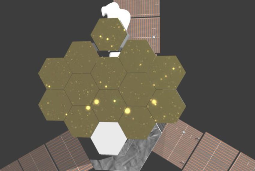
TABLE I
                            C HARACTERISTICS OF CURRENTLY OPERATIONAL OR PLANNED SPACE TELESCOPES
                   Mission         Launch        Orbit                      Spectral band                Primary mirror
                  HUBBLE        NASA, 1990    LEO, 547 km               Near-IR, Visible, UV                 2.4 m
                HERSCHEL         ESA, 2009    Sun-Earth L2         Far-IR, sub-mm (55 - 672 µm)              3.5 m
               JAMES WEBB       NASA, 2021*   Sun-Earth L2   Visible (orange) to mid-IR (0.26 - 28 µm)       6.5 m
                  EUCLID         ESA, 2022*   Sun-Earth L2                 Near-IR, Visible                  1.2 m
                   PLATO         ESA, 2026*   Sun-Earth L2                     Visible                         **
                 LUVOIR-A       NASA, 2039*   Sun-Earth L2               100 nm - 2.5 µm                     15 m
                  * Expected launch date                     ** PLATO uses several small cameras instead of a large mirror

   Assembling a large space structure implies putting to-         ground, then taken apart and launched to be reassembled
gether modular components in an ordered fashion, dictated         in space. Other requirements for the new generation of
by a high level master plan that indicates the relative po-       space telescopes include serviceability to allow replacement
sitioning of each part. Common robotic systems in space           and upgrading of instruments and subsystems as required,
applications have a small degree of autonomy. The execution       refueling and repairing on demand, and expandability, i.e.
of tasks usually relies on remote operations, which require       incremental enlargement of the aperture over time when the
an appropriate feedback channel for the operator, typically       design allows it. The key question for this new approach
affected by substantial time delays. The concept of shared au-    is when does in-space assembly of telescopes represents an
tonomy increases the dexterity of such systems and reduces        advantage (lower risk, lower price) with respect to building
the effort for the operators in difficult tasks. Nevertheless,    them on earth and sending them as a single piece.
remote operation approaches have limited use when it comes           The technology areas required for in-space assembly of
to the assembly of complex structures. Because of the fine        telescopes have different levels of maturity:
granularity of assembly tasks, classical remote operation            • High maturity: launch vehicles, mirror segment fabrica-
becomes unfeasible as it consumes substantial amounts of               tion
time for the synchronization of operator commands and                • Medium maturity: Segmented mirror wavefront and
manipulator actions. Therefore, a robotic assembly system              jitter control, robot hardware (arms)
should be capable of performing autonomously a sequence              • Low maturity: autonomous assembly, in-space assembly
of operations or even the complete assembly task.                 The aspects with lower maturity level are related to the
   Autonomous operations in space are still very challenging,     assembly process, i.e. technologies required to assemble
and there have been a limited number of demonstrations on-        a large diameter telescope in space and guarantee the same
orbit. The first successful demonstration of an unmanned          level of optical performance as a ground-assembled tele-
spacecraft to conduct autonomous rendezvous and docking           scope, and autonomous assembly, i.e. assembly processes
operations was done by NASDA in 1999 on ETS-VII. It was           carried out by robots without intervention of astronauts or
the first satellite equipped with a robotic arm that allowed      ground control. Different approaches have been proposed to
ESA to conduct the VIABLE experiment, demonstrating               achieve in-space assembly of telescopes, some based on high
computer vision support for autonomous robot control. Sev-        precision formation flying of satellites carrying individual
eral robotic arms are now present on board the ISS, including     mirror components, and some others for in-orbit assembly of
Canadarm, Dextre and Kibo, but for now they are all               the modular structure via a robotic servicer satellite carrying
teleoperated. Autonomous robotic assembly of space systems        some sort of robotic manipulator. An overview is provided
has been demonstrated on ground for planar truss and beam         below.
structures, but their test in orbit and with more complex         A. Deployable structure
structures still remains a challenge. Among the missions
                                                                     The James Webb Space Telescope likely represents the
under development, NASA’s Restore-L and DARPA’s RSGS
                                                                  largest size of aperture that can be achieved using a de-
are expected to demonstrate in the near future the autonomy
                                                                  ployable structure for a single-launch telescope. The JWST
and dexterity required for on-orbit assembly. An overview of
                                                                  has a 6.5 m mirror composed of 18 hexagonal segments,
current technologies for in-space assembly is provided in [6].
                                                                  and its backplane truss is separated in three hinged sections
   For space telescopes, current monolithic designs have          such that the primary mirror fits into the Ariane 5 rocket
reached the limits of the available cargo areas in launch ve-     fairing, with 5 m diameter. The unfolding process must
hicles. To push forward the size of space telescopes, current     be carried out autonomously in space. For the JWST, a
engineering approaches aim for a deployable structure, which      successful deployment depends on the correct performance
can be packed inside the current cargo areas, or a modular        of 40 deployment mechanisms and 178 release mechanisms.
design that can be deployed and assembled in space. For           Testing these sequences on ground is difficult due to the
the latter, a trade-off of risk vs. cost must be done between     presence of gravity loads, which do not actuate when the
first time assembly and reassembly, i.e. either the telescope     unfolding process occurs in orbit. JWST was not designed
components are directly launched and assembled for the first      for servicing, mainly due to its location in the L2 point of
time in space, or the telescope is assembled and tested on        the Sun-Earth orbit (SEL2).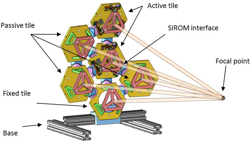
As the HST approaches its predicted lifetime, different          employed. In general, for free-flying based methods to be
projects have looked at a post-HST UVOIR Telescope.                 practical, the majority of elements involved in the process
For a single deployable structure, NASA’s project ATLAST            should be “dumb”, i.e. not have propulsion capabilities, and
(Advanced Technology Large Aperture Space Telescope) is             only a few active spacecrafts would then be required to create
close to the upper limit of payload capacity for a fully filled     the final assembly. While these proposals provide low risk
aperture telescope. This study proposed a 8 m monolithic            technical demonstrations, they do not scale well for larger
telescope and two segmented telescopes with 9.2 m and               assemblies.
16.8 m aperture, which would still fit in the cargo area of
heavy lift launchers [7].                                           C. Assembly using robotic manipulators
   For achieving a Large Ultraviolet Optical Infrared Tele-            A conceptually simple way to create large space structures
scope (LUVOIR), two architectures have been proposed:               is using robotic manipulators mounted on top of an aircraft.
LUVOIR-A, a 15 m segmented, on-axis telescope, and                  The advantage of this approach is that the same robotic
LUVOIR-B, a 8 m segmented, off-axis telescope [4].                  spacecraft can be reused to carry out multiple tasks including
LUVOIR-B was designed for being deployed using a con-               repairings, upgrades, or refueling, thus one single assembly
ventional, heavy-lift launch vehicle, while LUVOIR-A is             mission would not have to pay for the full cost of the system,
designed to profit from the extended capabilities of the SLS        as it is reusable and mobile (can be used at different orbits).
Launcher. Both telescopes would be deployed in the SEL2                For the case of assembling a telescope, the components
point, and are designed to be serviceable and upgradeable.          of the structure can be taken to orbit in single or multiple
If they are approved, their expected launch date would be in        launches. The selection of the size of the mirror tiles influ-
late 2030s.                                                         ences the number of assembly and alignment steps required
                                                                    to complete the full structure. Also, there must be a metrol-
B. Free-flying satellites                                           ogy system capable of measuring the pose of each individual
   Satellites flying in a precise formation can mimic the           tile to command possible corrections that reduce the pointing
behavior of a rigid structure, even without physical docking.       and wavefront errors. A separate vehicle can be used to to
For instance, ESA is preparing the Proba3 mission (PRoject          carry equipment for diagnosis and calibration of the primary
for OnBoard Autonomy)6 , scheduled to launch in 2020,               mirror, providing also a third point of view for an accurate
where two satellites will be autonomously flying in tandem          and cost-effective way to supervise the assembly process.
formation. The two satellites, derived from the ESA’s stan-            Different robotic systems have been proposed for these
dard Proba platform, will form a 150 m long coronograph             assembly processes, including:
to study the Sun; one satellite will carry the coronograph,            • Single and dual arm manipulators rigidly attached to a
while the other one will be the occulter.                                 spacecraft, which greatly limits their reachability.
   Small satellites (e.g. up to 1000 kg) can play a significant        • Wheeled robots that move on rails on top of a satellite or
role on in-space assembly operations due to their low cost                on top of the structure being assembled, which extends
and lead time [8]. For instance, AAResT is a mission led                  the reachability of the arm.
by the Surrey Space Center, consisting of two MirrorSats               • Robots using some climbing (or walking) strategy that
(3U nanosatellites) that carry an electrically actuated adapted           allows the robot to move on top of the spacecraft,
mirror, and a central satellite, CoreSat (9U nanosatellite)               attaching and detaching from the satellite as required.
carrying two fixed mirrors and a boom-deployed focal plane             Note that in the case of walking robots, their mobility
assembly camera [9]. The two MirrorSats can autonomously            should be enabled via standard connection interfaces, e.g.
dock and undock from the CoreSat to create different config-        iSSI7 or SIROM8 , conveniently located at different places
urations and guarantee a proper image at the focal plane. The       on the spacecraft. In this way, the robot’s working volume
three satellites are meant to be launched as a single package       is not restricted to the reachability of the arm, but can be
of about 30 kg, with foreseen launch date in 2020.                  extended through the multiple attachment points.
   A swarm of satellites, each one representing a module of            Inspired by the segmented optics developed for the 10 m
the structure, can also be used. In this case, each satellite can   Keck telescope in Hawaii, Boeing proposed AAST (Au-
fly autonomously, and dock and undock from other modules.           tonomously Assembled Space Telescope), a 10 m aperture
One example of such concepts is the GOAT mission (Giant             Cassegrain optical telescope consisting of hexagonal rings of
Orbiting Astronomical Telescope), proposed by Surrey Space          segmented mirror tiles (SMTs), and assembled with robotic
Center [10]. In these rendezvous and docking approaches             manipulator arms [11]. The focus of this proposal was on the
the physical docking can take multiple forms, for instance          minimization of the number of segments for the telescope
using mechanical or electro-magnetic means. The risk and            while optimizing the segment size and layout to ensure the
complexity of these formation-based approaches stems from           best optical performance of the primary mirror.
the operation of several spacecraft in close proximity; col-           Building upon heritage from the JWST, a modular de-
lision avoidance techniques and precise navigation must be          sign with mirror segments for a 20 m aperture UV-Optical
  6 http://www.esa.int/Our_Activities/Space_                          7 http://www.iboss-satellites.com/material

Engineering_Technology/Proba_Missions                                 8 http://www.h2020-sirom.eu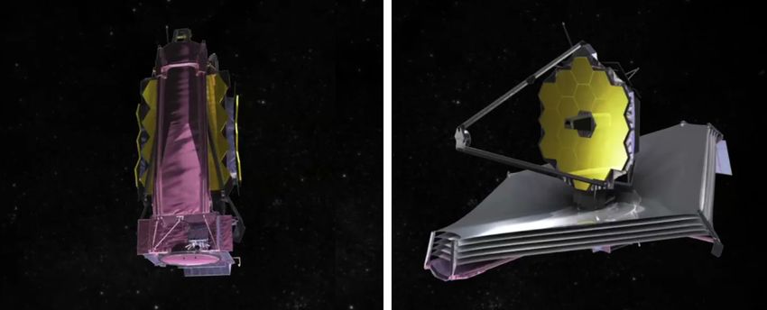
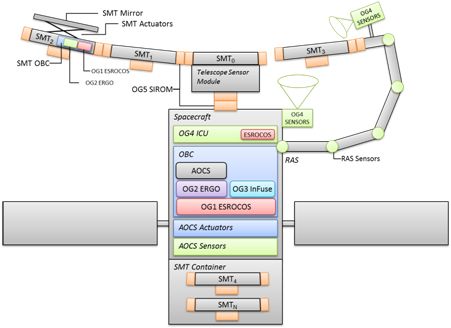
telescope was proposed [12]. Two different mirror panel          multiple autonomous agents. Several steps have been already
configurations are considered, with either 12 and 16 mirrors.    validated onboard the ISS and on a ground-based testbed
These mirror panels would be assembled on ground, so that        called SWARM.
the installation of mirrors on the backplane panels and the
optical verification can be carried out on Earth. Then, the          III. PULSAR:P ROTOTYPE OF AN U LTRA L ARGE
panels would be launched to be assembled into the primary                    S TRUCTURE A SSEMBLY ROBOT
mirror in space, using both robot and astronaut workforce.          The European Commission has set up the “Space Robotics
   A concept for assembly of a large reflector in GEO orbit      Technologies” Strategic Research Cluster (SRC) in the Hori-
was presented in [13]. Several elements are launched into        zon 2020 program, with the goal of enabling major ad-
MEO (Medium Earth Orbit) and assembled using multi-              vances in strategic key points of this domain. To fulfill
ple robotic arms. The structure then spirals up to GEO           this objective, an European roadmap composed of three
(Geosynchronous Earth Orbit) using solar sails as a propul-      successive calls (2016, 2018 and 2020) has been defined
sion system. For performing the assembly in GEO, a new           by the PERASPERA10 consortium, composed by the main
technique called Equilibrium Shaping was proposed, to find a     European space agencies. The first activities in the 2016
final configuration using autonomous planning based only on      call have addressed the design, manufacturing and testing
sensing the state of the other agents involved in the process.   of reliable and high performance common robotic building
   To reduce the running cost of a space telescope mission,      blocks for operation in space environments. The specific
Northrop Grumman Aerospace Systems proposed the con-             objective of the second call in 2018 was to integrate these
cept of an Evolvable Space Telescope (EST), where the            building blocks into ground-based demonstrators, towards
construction and launch of the telescope is conducted in         applications of space robotics in the field of both orbital
several stages, each one providing a complete functional         and planetary use.
telescope whose capabilities can be extended over time
[14], with an expected total lifetime of over 40 years. The
original proposal included a first stage to produce a 4x12
meter telescope using mirror tiles with 4 m diameter, which
would be extended in two stages to create a 12 and 20 m
aperture telescope. The advantage of such scaled approach
is the staged budget, and reduced risk for schedule slip and
descoping due to budget restrictions.
   The concept and architecture for a robotically assembled,
modular space telescope (RAMST) was presented in [15].
The exemplary application is the assembly of a 100 m aper-
ture telescope assembled in Earth orbit and operated at SEL2.
The approach uses four independent aircrafts carrying the
primary mirror, the optics and instrumentation unit (OIU),
the metrology unit, and a sunshade. The primary mirror
consists of hexagonal truss modules that are first deployed
and attached, and then the mirror modules are attached to         Fig. 3.   PULSAR architecture, based on previous components (OGs).
the underlying truss structure. The assembly is carried out
by a six-limb robotic manipulator with supervised autonomy,         The PULSAR (Prototype of an Ultra Large Structure
which can travel over the truss structure to perform the         Assembly Robot) project is related to OG8 (Operational
required tasks.                                                  Grant 8) (Fig. 3). It aims at developing and demonstrating
   An initial hardware-in-the-loop test of assembly of a         the technology that will allow the on-orbit precise assembly
telescope under micro gravity conditions has been proposed       of a large primary mirror by an autonomous robotic system.
by MIT and NASA Goddard with the program ALMOST                  As discussed above, the new generation of space telescopes
(Assembly of a Large Modular Optical Telescope) [16]. The        requires multiple mirror tiles (individually adjustable) and
concept uses the SPHERES9 , a floating robotic platform          multiple interfaces, and therefore a meticulous process for
deployed inside the ISS since 2006. The proposed experiment      autonomous assembly. This is fulfilled by perception and
uses 3 SPHERES to assemble a floating telescope with             planning algorithms that make use of extended mobility
0.76 m aperture inside the ISS; each SPHERE would act as         for very large structures. The latter requires a controlled,
a vehicle that carries out one part of the assembly (central     stable spacecraft during operations, and a spacecraft structure
module, mirror panels, and camera to provide supervision         that provides attachment and housing for the robotic arm
of the process). The experiment would test the full as-          and mirror tiles. The approach in PULSAR involves two
sembly sequence in a realistic free-floating environment,        physical demonstrators (one focused on assembling a fully
with actuator and sensing constraints coming from using          functional section of a telescope mirror on Earth conditions,
  9 https://www.nasa.gov/spheres                                   10 https://www.h2020-peraspera.eu
and the other one on assembling a very large structure in         a preferred solution is using a smaller robotic manipulator
low gravity conditions - underwater), and one simulation-         (typically 1 to 2 m length) but with the ability to move within
based demonstrator (evaluation of the PULSAR technology           the structure. Two main alternatives have been analyzed
in space conditions).                                             for providing the required mobility: a walking manipulator,
                                                                  and mobility within a rail. The lower complexity of the
A. Requirements for a future PULSAR-like mission                  second option makes it preferable at this stage of the study
   A PULSAR mission would use an Ariane 6 launcher. This          (Fig. 4). Although no space applications are known so far
launcher will provide a maximum payload of 8 Tn for injec-        implementing this kind of technology, it is common on
tion on a transfer orbit to SEL2 [17]. The choice of SEL2         ground applications. On the other hand, different walking
is motivated by two main aspects: first, the apparent steady      manipulators have been implemented for space applications,
position of the spacecraft with respect to the Sun and Earth,     including ERA and SSRMS [18]. A proof of concept of
thus ensuring constant sun incidence without eclipse, and         a walking manipulator for a space-based assembly applica-
second, the lower gravitational forces, minimizing effect of      tion is currently under development in the project MOSAR
disturbances and enabling more accurate and stable pointing       (OG9) [19]. Adaptable perception, localization and mapping
of the telescope. The JWST mission is also planned to exploit     techniques are required to guide the assembly process. After
these benefits. HST, on the other hand, operated in LEO orbit,    the telescope is assembled, a metrology system needs to be
mainly because the spacecraft was specifically conceived for      employed for verifying the location and orientation of each
receiving in-orbit servicing. With various servicing missions,    mirror tile, so that adjustments can be made to achieve the
repairing and refueling the spacecraft, the telescope has         required accuracy and precision.
maintained its mission for almost 30 years. Nevertheless,
future space telescopes are less suitable for this approach: as
they are bigger and heavier, and with more demanding point-
ing specifications, the environment of LEO orbits makes the
mission a hardly solvable technical problem for the Attitude
Orbit and Control System (AOCS). Moreover, complexity of
operations is added to manage eclipses and occultation of
targets by the Earth or the Sun. Summarizing, the following
preliminary requirements could be highlighted for a future
European Space Telescope:
   • Orbit: SEL2, enabling observation of space and distant
     celestial bodies without interference of Sun or Earth.
   • Launcher: Ariane 6, limiting the mass of the telescope
     to 8 Tn.
   • Launch date: between 2030 and 2035. A launch before
     2030 is not realistic due to the significant developments
     needed, and after 2035 the interest on a PULSAR-
     like mission might be limited, if LUVOIR-A is already
     operational.
   • Primary mirror: 8 to 10 m diameter.

B. Requirements for in-orbit assembly of the primary mirror
   A mission of this type requires that the basic modules
(including supporting structures, mirrors, mirror mountings
and control interfaces) are designed, stacked and packaged
for the required launch vehicle fairing. After the modules
are placed in orbit, they could be assembled anywhere in
space. The assembly platform requires robotic dexterous ma-          Fig. 4.   Concept for precise assembly of mirror tiles in PULSAR.
nipulation for retrieving the tiles, deploying and joining the
basic components. After the telescope modules are retrieved,
they must be positioned and aligned using suitable standard       C. Demonstrator of precise assembly of mirror tiles
interfaces for latching structural elements and providing         (dPAMT)
power, thermal and data connectivity.                                The demonstrator for precision assembly of mirror tiles
   Given the size of the mirror envisaged for a space-based       will show the capabilities to autonomously assemble several
telescope, the robotic arm would need some kind of mobility       mirror tiles following specifications from a Master plan.
in order to reduce its required length. A very long robotic       This demonstrator will be implemented with a combina-
manipulator would make very difficult to meet the accurate        tion of adaptable perception, integrated assembly and grasp
position and orientation requirements needed for assembly;        planning, and compliant control of the manipulators. The
assembly demonstrator will rely on an assembly planner, for underwater operation, including the connectors and the
which integrates a grasp planner and a motion planner, for mirror tiles.
autonomously creating a master plan for the overall process
E. Demonstrator of In-Space Assembly in Simulation
starting with the specification of the desired assembly. The
(dISAS)
system automatically decomposes a given assembly into a
task sequence, which is then mapped to a sequence of This last demonstrator will address the challenge of au-
appropriate robotic skills. The skills exploit the capabilities tonomously deploying a large structure in space while ensur-
of a lightweight and highly sensitive robotic manipulator, ing the stability and safety of the spacecraft. To compensate
the KUKA iiwa, for achieving compliant operations that the limitations of the fidelity of low-gravity facilities (such
guarantee successful execution of the robotic skills even in as time-delay for the robotic platform and water-drag instead
the case of positional or sensorial uncertainties. Standard of neutral buoyancy), simulation means are retained as the
interfaces will be used both at the end point of the robotic third demonstrator. This includes accurate physical mod-
arm and at the mirror tiles, to facilitate the retrieval and els of spacecraft, robotic assembly system, and segmented
repositioning of the SMTs. The main limitations of the mirror tiles, to estimate torque disturbances involved in the
demonstrator will be gravity and the robotic arm’s payload deployment, as well as robust controllers to manage them.
limit, which restricts the achievable size of the assembled Software coming from the previous OGs will be embedded,
structure. including the European Space Robotics Control Operating
Visual servoing will be an important component for ver- System (ESROCOS)11 , European Robotic Goal-Oriented au-
ifying the execution according to the nominal plan. Ad- tonomous controller (ERGO)12 and data Fusion for Space
ditional external sensors are required to provide a ground robotics (InFuse)13 . The objective is to demonstrate that the
truth measurement for robot positioning and motion, and deployment of large structures and active tessellated mirror
for measuring the success of the assembly process for the control can be carried out on-board a spacecraft respecting
space telescope. An external measuring device will be used the AOCS requirements.
to verify the pose of each individual mirror tile in order The AOCS must be designed to support all mission’s
to validate the geometry and configuration of the primary needs from launch and early orbit phase (LEOP) to satellite
mirror, and to define the adjustments required to perform an disposal. The satellite must implement at least the following
optical alignment to a given focal point (Fig. 5). operational phases: launch phase, transfer phase, deployment
phase, mission phase, and de-orbit phase. Each phase is
supported by one or more AOCS modes [20]. In the context
of PULSAR, our main concern will be the design of efficient
controllers for the deployment and mission phases. The
deployment phase is normally entered when the satellite
has finally reached the target orbit and all the satellite’s
appendages (i.e. solar arrays, antennas, instruments) are
deployed. The mission phase begins after the deployment,
and it is maintained up to the end of mission before satellite
disposal.
The deployment phase is certainly the most challenging as
far as the control design problem is concerned. During this
time period indeed, as already observed in the early work
Fig. 5. Validation of the mirror adjustment in PULSAR. with ETS-VII [21], it is important to stabilize the attitude
with a reasonable accuracy to keep the communication link
D. Demonstrator of large structure assembly in free floating despite torque perturbations generated by the robotic arm.
environment (dLSAFFE) Moreover, the robotic arm is used to build the primary mirror
To simulate on-orbit conditions, in particular the effects from tiles that are progressively deployed from the main
of micro-gravity, the autonomous assembly of a large seg- body. As a result, the inertia of the total satellite varies rather
mented mirror in underwater conditions will be demon- slowly but significantly during this deployment phase. Many
strated. This needs advanced mobility to overcome the limits different strategies have been developed in the literature over
of robotic arm adaptability to the accumulated assembly the past thirty years to handle attitude control problems in
errors, and an optimal Attitude and Orbit Control System the presence of time varying inertia, for instance Adaptive
(AOCS) to stay in the required pose. An underwater platform Control Techniques for Linear Time Varying systems [22],
endowed with a robotic manipulator will be used, and [23], linear parameter varying models [24], or robust control
thrusters in the platform will help to control the effects of techniques that consider the variations in the inertia matrix
impulsive forces created during the assembly operation. The as time-varying uncertainties [25].
extended mobility of the arm will show the feasibility of 11 https://www.h2020-esrocos.eu/
assembly operations of a large structure. For this demon- 12 https://www.h2020-ergo.eu/
strator, all the technical sub-systems have to be adapted 13 https://www.h2020-infuse.eu/During the observation phase, the inertia matrix does [7] H. Thronson, M. Bolcar, M. Clampin, J. Crooke, L. Feinberg,
not change significantly. However, pointing stability is the W. Oegerle, N. Rioux, P. Stahl, and K. Stapelfeldt, “Path to a
UV/optical/IR flagship: review of ATLAST and its predecessors,” J.
driving requirement for high-quality imaging in a space of Astronomical Telescopes, Instruments, and Systems, vol. 2, no. 4,
telescope [26]. The full primary mirror tends to generate p. 041210, 2016.
badly damped and rather low frequency torque perturbations. [8] S. Eckersley, C. Sanders, D. Gooding, M. Sweeting, C. Whiting,
M. Ferris, J. Friend, L. Forward, G. Aglietti, A. Nanjangud, P. Blacker,
The main control design issue will then consist of enhanced C. Underwood, C. Bridges, and P. Bianco, “In-orbit assembly of
weighting functions tuning to optimize the compromise be- large spacecraft using small spacecraft and innovative technologies,”
tween a reasonable pointing accuracy and disturbance rejec- in Proc. Int. Astronautical Congress (IAC), 2018.
[9] C. Underwood, S. Pellegrino, H. Priyadarshan, H. Simha, C. Bridges,
tion. The general structure of the AOCS during deployment A. Goel, T. Talon, A. Pedivellano, C. Leclerc, Y. Wei, F. Royer, S. Fer-
will be kept in order to facilitate control switching from the raro, M. Sakovsky, M. Marshall, K. Jackson, C. Sommer, A. Vaid-
deployment phase to the observation phase. hyanathanc, S. Vijayakumari, and J. Baker, “AAReST autonomous
assembly reconfigurable space telescope flight demonstrator,” in Proc.
Int. Astronautical Congress (IAC), 2018.
IV. F INAL DISCUSSION [10] C. Saunders, D. Lobb, M. Sweeting, and Y. Gao, “Building large
This paper provided an overview of different robotic telescopes in orbit using small satellites,” in Proc. Int. Astronautical
Congress (IAC), 2016.
technologies proposed for the assembly in space of a large [11] S. Basu, T. Mast, and G. Miyata, “A proposed autonomously assem-
telescope. While the paper primarily focused on the assembly bled space telescope (AAST),” in AIAA Space Conf., 2003.
of the telescope structure and primary mirror and the optical [12] N. Lee, P. Backes, J. Burdick, S. Pellegrino, C. Fuller, K. Hogstrom,
B. Kennedy, J. Kim, R. Mukherjee, C. Seubert, and Y. Wu, “Mod-
verification of the telescope, the full assembly process of the ular assembled space telescope,” SPIE Optical Engineering Journal,
telescope requires several additional steps, including assem- vol. 52, no. 9, 2013.
bling the metering structure, secondary mirror, other tele- [13] D. Izzo, L. Pettazzi, and M. Ayre, “Mission concept for autonomous on
orbit assembly of a large reflector in space,” in Proc. Int. Astronautical
scope components (optical train, cameras, sensors, reference Congress (IAC), 2005.
units), and providing power, thermal and data connectivity [14] R. Polidan, J. Breckinridge, C. Lillie, H. MacEwend, M. Flannerya,
for all the components. and D. Dailey, “An evolvable space telescope for future astronomical
missions,” in Proc. SPIE 9143, Space Telescopes and Instrumentation:
The European project PULSAR was also introduced, Optical, Infrared, and Millimeter Wave, 2014.
which aims to provide a first experimental verification for [15] N. Lee, P. Backes, J. Burdick, S. Pellegrino, C. Fuller, K. Hogstrom,
low-level technologies that need to be further developed for B. Kennedy, J. Kim, R. Mukherjee, C. Seubert, and Y. Wu, “Architec-
ture for in-space robotic assembly of a modular space telescope,” J.
in-space autonomous assembly of complex structures such as of Astronomical Telescopes, Instruments, and Systems, vol. 2, no. 4,
telescopes. This goal will be achieved through three different p. 041207, 2016.
demonstrators, based on a mobile robotic manipulator (for [16] D. Miller, S. Mohan, and J. Budinoff, “Assembly of a large modular
optical telescope (ALMOST),” in Proc. SPIE 7010, Space Telescopes
testing autonomous assembly and optical verification of the and Instrumentation: Optical, Infrared, and Millimeter, 2008.
telescope), an underwater platform (for testing assembly in a [17] F. Masson, A. Patureau, R. Epenoy, J.Vila, J. Bahu, C. Bonnal,
low gravity environment), and a simulation-based approach L. Baize, V. Leudiere, A. Pisseloup, E. Ferreira, C. Barbero, F. Ducerf,
and N. Bozhkov, “Ariane 6 and space tugs: an enabler for european
for testing a full mission. The final demonstrations will be exploration missions,” in Proc. Int. Astronautical Congress (IAC),
performed in 2021. 2017.
[18] V. Dubanchet, “Modeling and control of a flexible space robot to cap-
R EFERENCES ture a tumbling debris,” in Doctoral dissertation, École Polytechnique
de Montréal, 2016.
[1] N. R. Council, New Worlds, New Horizons in Astronomy and Astro- [19] P. Letier, X. Yan, M. Deremetz, A. Bianco, G. Grunwald, M. Roa,
physics. The National Academies Press, 2010. R. Krenn, M. Munoz, P. Dissaux, J. Sanchez, R. Ruiz, L. D. Filippis,
[2] J. Gardner, J. Mather, M. Clampin, R. Doyon, M. Greenhouse, G. Porcelluzzi, M. Post, M. Walshe, and P. Perryman, “MOSAR: Mod-
H. Hammel, J. Hutchings, P. Jakobsen, S. Lilly, K. Long, J. Lunine, ular spacecraft assembly and reconfiguration,” in Symp. on Advanced
M. Mccaughrean, M. Mountain, J. Nella, G. Rieke, M. Rieke, H. Rix, Space Technologies for Robotics and Automation (ASTRA), 2019.
E. Smith, G. Sonneborn, M. Stiavelli, H. Stockman, R. Windhorst, [20] L. Mazzini, Flexible Spacecraft Dynamics, Control and Guidance.
and G. Wright, “The James Webb Space Telescope,” Space Science Springer, 2015.
Reviews, vol. 123, no. 4, pp. 485–606, 2006. [21] M. Oda, K. Kibe, and F. Yamagata, “ETS-VII, space robot in-orbit
[3] M. Greenhouse, M. Drury, J. Dunn, S. Glazer, E. Greville, G. Henegar, experiment satellite,” in Proc. IEEE Int. Conf. on Robotics and
E. Johnson, R. Lundquist, J. McCloskey, R. Ohl, R. Rashford, and Automation (ICRA), 1996, pp. 739–744.
M. Voyton, “Status of the James Webb space telescope integrated [22] R. Middleton and G. Goodwin, “Adaptive control of time-varying
science instrument module system,” in Proc. SPIE 8442, Space Tele- linear systems,” IEEE Trans. on Automatic Control, vol. 33, no. 2,
scopes and Instrumentation: Optical, Infrared and Millimeter Wave, pp. 150–155, 1988.
2011. [23] K. Chen and A. Astolfi, “Adaptive control of linear systems with time-
[4] M. Bolcar, S. Aloezos, V. Bly, C. Collins, J. Crooke, C. Dressing, varying parameters,” in Proc. American Control Conference (ACC),
L. Fantano, L. Feinberg, K. France, G. Gochar, Q. Gong, J. Hylan, 2018, pp. 80–85.
A. Jones, I. Linares, M. Postman, L. Pueyo, A. Roberge, L. Sacks, [24] R. Jin, X. Chen, Y. Geng, and Z. Hou, “LPV gain-scheduled attitude
S. Tompkins, and G. West, “The large UV/Optical/Infrared surveyor control for satellite with time-varying inertia,” Aerospace Science and
(LUVOIR): Decadal mission concept design update,” in Proc. SPIE Technology, vol. 80, pp. 424–432, 2018.
10398, UV/Optical/IR Space Telescopes and Instruments: Innovative [25] L. Shi, J. Katupitiya, and N. Kinkaid, “A robust attitude controller for
Technologies and Concepts VIII, 2017. a spacecraft equipped with a robotic manipulator,” in Proc. American
[5] K. Nottensteiner, T. Bodenmüller, M. Kassecker, M. Roa, A. Stemmer, Control Conference (ACC), 2016, pp. 4966–4971.
T. Stouraitis, D. Seidel, and U. Thomas, “A complete automated chain [26] L. Blackmore, E. Murray, D. Scharf, M. Aung, D. Bayard, P. Bru-
for flexible assembly using recognition, planning and sensor-based garolas, F. Hadaegh, A. Lee, M. Milman, S. Sirlin, and B. Kang,
execution,” in Proc. Int. Symp. on Robotics (ISR), 2016, pp. 1–8. “Instrument pointing capabilities: past, present, and future,” in Proc.
[6] M. A. Roa, K. Nottensteiner, A. Wedler, and G. Grunwald, “Robotic AAS Guidance, Navigation and Control Conf., 2011.
technologies for in-space assembly operations,” in Symp. on Advanced
Space Technologies for Robotics and Automation (ASTRA), 2017.You can also read