Brick Veneer Best Practice Guide Practice Guide - The Brickery
←
→
Page content transcription
If your browser does not render page correctly, please read the page content below
April 2021

Brick Veneer Best
Practice Guide
Practice Guide
Brick Veneer Best Practice Guide - Preface

Preface
This document is the result of a collaboration between the collective of Brick & Blocklayers
associations within New Zealand and the manufacturing and distribution sector under the guise of the
‘Master Brick & Blocklayers of New Zealand.

Since 1991, New Zealand has had a ‘performance based’ Building Code in place. What this means is
that there is no set, one way that buildings within New Zealand MUST be built but instead focus is
placed on how a building should perform once built.

The Ministry of Business, Innovation and Employment (MBIE) provides to the industry a set of
‘Acceptable solutions’ as a means of complying with the Building Code. These documents however are
not compulsory and at times the Best Practice Guide for Brick Veneer makes recommendations that
are not part of, or contradict the Acceptable solutions. In these areas, we have endeavoured to point
you towards information or independent study reports that show that these ‘alternative solution
proposals’ should also meet the performance requirements of the NZ Building Code.

As an Industry, we believe that we also need to consider Workmanship Quality with our guidance.
Workmanship Quality describes the brick work that is not related to building performance but
the aesthetic finish that customers expect from Brick work.

An acceptable Workmanship Quality standard has been met if a brick veneer has been laid to meet the
performance requirements of the Building Code and achieves no visible defects when viewed by a
6.1m with diffused light viewing distance as per manufacturer’s specifications. This may be achieved
without meeting all of the tolerances contained within this Best Practice Guide.

It is recommended, when planning the design of a Brick Veneer that you engage a bricklayer early on
for their knowledge of design and product.

Master Brick & Blocklayers asks that you consider engaging the products and services of our members
who have contributed and made this document possible.

                                                                                         1|Page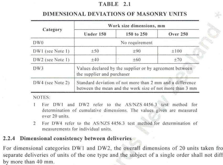
The Brick Cavity

The brick cavity has meant that most brick homeowners' managed to avoid owning a leaky home

Designing and building brick cavities
A ‘cavity’ or ‘cavity gap’ is an area of space between the timber framing and the brick veneer
that enables sufficient airflow and drainage to dry any moisture that may penetrate the brick
veneer.
Without a cavity, any moisture would be trapped between the brick and timber and may
cause the timber to rot which has been the case with other cladding products, particularly
prior to 2004 resulting in ‘leaky home syndrome’.

CAVITY WIDTH
Unless a building consent states otherwise, a cavity should be between 40–75mm to comply
with
E2/AS1 which is the acceptable solution for claddings.
Designers and bricklayers should familiarise themselves with Section 9.2.6 Cavities and
review Figure
73Dof E2/AS1. You can read this documentation here: E2/AS1 (part4).
It is important to remember that measurements for cavities are taken from the point where
the brick tie is secured to the framing (which may not necessarily be the line of the
supporting structure).
The cavity width should be clearly marked on all working drawings.
Master Brick & Blocklayers recommends that cavity gaps are designed to a 50mm cavity.
This provides a 10mm tolerance for variations in the framing or slab and accommodates
should plywood bracing be a requirement. E2/AS1 allows for a maximum overhang of
20mm.

                                                                                   2|Page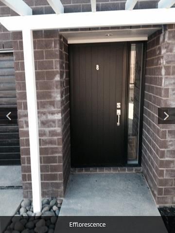
SLAB RECESSES
As a further weather tight design precaution brick veneers should be designed and
constructed with a slab recess. This means that the veneer should be extended below the
final floor level to ensure that any moisture that penetrates the cavity drains past the
flooring level and out through the weep holes. This is intended to prevent moisture from
potentially pooling and running to the inside of the dwelling.
Designers and Bricklayers should familiarise themselves with Section 9.2.5 and Figure
73DofE2/AS1 for options of slab recess. You can read this document here: E2/AS1 (part4)
E2/AS1 requires a step down of 50mm or more.
Master Brick & Blocklayers recommends a step down of 90-100mm and the placement of
a sloping fillet at the base of the cavity to direct water to the outside.

DAMP PROOFING OF SLAB RECESSES
The slab edge and the bottom of the cavity should be sealed to prevent any moisture sitting
in the bottom of the cavity from entering the dwelling.
E2/AS1 requires that damp proofing material be either:
Rebates lower than the ground; or
Two coats of a bituminous liquid; or
1mm of butyl rubber or bituminous sheet; or
0.25mm polythene or polyethylene damp proof membrane.
 If the rebate is above ground level then either 1mm of butyl rubber or bituminous sheet or
0.25mm polythene or polyethylene damp proof membrane are the only options available.

WIDTH OF SLAB RECESSES
The width of the recess at the base of the veneer, where the brick sits upon, is governed by
three factors:
The desired cavity width;
The width of the brick;
The amount, if any, that the brick will overhang the foundation.
If the brick product has not yet been selected, or if it is subject to change then it is
important to ensure that this ledge is designed with flexibility.
Master Brick & Blocklayers recommends designing a 120mm wide ledge and planning to
overhang the brick 10mm to provide a drip edge.

ENSURING THE CAVITY IS CLEAR
A clean cavity, free of mortar bridging the gap, is essential for preventing moisture
transference. NZS4210:2001 Section2.7.1.7 advises that mortar should not encroach into
the cavity more than 5mm.
Master Brick & Blocklayers recommends specifying and installing ‘wash-outs’. A ‘washout’
involves laying every corner brick and every subsequent brick at 800mm centres on a bed of
sand (thus coinciding with weep hole requirements). Once the veneer is approximately
800mm high, these bricks are removed to facilitate the regular washing out of mortar at the
base of the cavity.

                                                                                   3|Page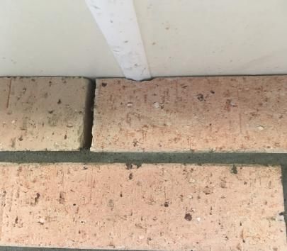
Mortar

Mortar is used to hold bricks together and fill and seal any gaps around them. Basically
mortar used in brick veneer is a mixture of sand, cement, ad mixture and water. It is however
critical that the components of mortar are properly proportioned and mixed correctly.

MIXING MORTAR
For brick veneer to function correctly it is important that the bricks are stronger than the
mortar. This will ensure that in the event of seismic activity the tensile bond strength or
adhesion of the mortar will fracture rather than the bricks themselves.

NZS4210:2001 provides for a strength requirement for structural masonry but not for brick
veneer and states that mortars for veneers shall follow the strength requirement of the
masonry suppliers.

In 2011 BRANZ released SR258 – Critical properties of Mortar for good seismic performance
of brick veneer.
You can read this report here:
http://www.branz.co.nz/cms_show_download.php?id=8270db8e7e10636a60e5faedc2cd28
0ee6041b62

This research indicates that mortar strength should be at least 6MPa and advises that this
can be achieved with mortar mixes of 4:1 sand to cement.
A hydration process occurs between the water and cement which causes the cement to
harden and bind with the sand and therefore cause the mortar to ‘set’. If the mortar shows
signs of powdering that may mean that hydration has not occurred properly and the
resulting veneer will need to be pulled down.
One of the most common causes of mortar powdering is rapid loss of moisture when the
bricks are first laid. If the temperature exceeds 27 degrees Celsius then it is important to
ensure that the bricks are kept damp for the first 24 hours.
In summer any mortar which is more than 1.5 hours old should be discarded and for
temperatures below 5 degrees Celsius mortar should be discarded after 2 hours.
NZS4210:2001 Section 2.2.2.2(e) advises that bricklayers should avoid re-tempering mortar
with water.
Mixing good mortar is a skill obtained through experience. Mixing times, humidity levels and
even the type of sand used can all have an effect on the final product. Bricklayers should
consider using bagged mortar for quality control issues and to obtain compliant mortar
strength.
Chemical admixture shall comply with NZS 3113:1979 or AS 1478.1:2000 Admixtures shall
be dosed in accordance with the manufacturer’s instructions.
Master Brick and Blocklayers ask that if you do use bagged mortar that you support our
manufacturing members:
Dricon (Firth)
http://www.firth.co.nz/product-information/dricon/dricon-product-range/trade-
mortar.aspx

                                                                                     4|Page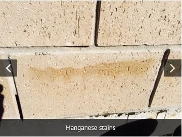
Mortar Joints

‘Mortar joint’ is the term for the space of mortar between bricks. According to
NZS4210:2001 the average thickness of a mortar bed, cross or perpend joint should be
10mm +/- 3mm. A joint thickness of up to 20mm may be accepted on the bottom course to
accommodate any slab level issues.
While the thickness of mortar needs to ensure that an adequate seal and bond is achieved,
the mortar joint itself also provides an aesthetic value to the brick veneer. Different looks
and weather tight properties can be achieved by creating different patterns in the mortar
joint.
Varying mortar joint styles are created by bricklayers by running jointers, rakes or beaders
across the mortar before it sets to achieve the desired look.
The most common mortar joint types are – grooved, weathered, ‘V’, raked, extruded or
flush.

GROOVED JOINT – Also known as Concaved or rolled. This type of joint is formed by using a
curved steel jointing tool. Its recessed profile and tight seal mean that it is very effective at
resisting moisture penetration. This type of joint can be good for hiding small irregularities.
Should be tooled to a maximum depth of 6mm after initial stiffening has occurred. The delay
of tooling is vital if a tight weatherproof joint is to be produced in horizontal but particularly,
vertical joints. It is recommended that all slurry coated bricks should use a grooved joint.

WEATHERED JOINT – The mortar forms a joint that is recessed from the bottom to the top.
This type of joint can give brickwork a neat, ordered appearance. While not as
weathertight as Grooved and ‘V’ joints, it can be used on external walls and should be
tooled to after initial stiffening has occurred. The delay of tooling is vital if a tight
weatherproof joint is to be produced in horizontal but particularly, vertical joints.

‘V’ JOINT – This type of joint is formed with a V-shape jointer (or trowel). This type of
joint can be good for hiding small irregularities. This joint has good weathertight properties.
Should be tooled to a maximum depth of 6mm after initial stiffening has occurred. The delay
of tooling is vital if a tight weatherproof joint is to be produced in horizontal but particularly,
vertical joints.

RAKED JOINT – For this type of joint the mortar is raked out and once pointed and tooled
shall not exceed a maximum depth of 6mm. It is important to compact the mortar to
improve its weather tight performance, this design creates a form of ledge where water can
pool.

EXTRUDED JOINT – This type of joint is formed without tooling. It is caused naturally as
excessive mortar squeezes out between the bricks. Exposure to weather may degrade an
Extruded joints appearance.

                                                                                       5|Page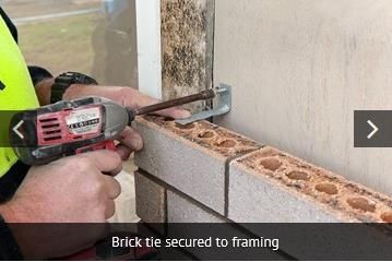
FLUSH JOINT – Master Brick & Blocklayers does not recommend the use of flush joints
unless they are compacted. If the mortar is flush jointed and not compacted it can lead to
the following issues:

• When veneer is to be honed, the mortar can ‘flick’ out with honing process.
• When brick is to be plastered it can lead to hairline cracking in the plaster where the
outline of the brick can be seen.

The type of brick selected plays a part in which type of mortar joint will work
best. Straight edged bricks with a ‘Vitratectm ‘or ‘slurry’ coat must use grooved (rolled)
joints whereas colour through bricks with rumbled edges are better with raked joints.

Master Brick & Blocklayers recommends discussing the Mortar Joint options for your
chosen product with the installer, who will take into account the Manufacturers
recommendations.

                                                                                    6|Page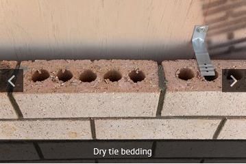
Brick Ties

Brick ties provide strength and flexibility to brick veneer.

Brick Ties
As the name suggests, a brick tie is a connector that ties the brick veneer to the structural
framing of a building. This feature both prevents the bricks from simply falling away from
the framing and they also increase the strength of the brick veneer by transferring some of
the force away from the brick and on to the structural element.

BRICK TIE DURABILITY
As brick ties are considered a structural element they are required under the New Zealand
Building Code to have a 50 year durability.
If a building is within 500m of the high water mark or within 100m of a tidal estuary (also
known as the ‘sea spray zone’) then stainless steel brick ties will be required. If you are
unsure of this then we recommend talking with your local council before commencing
design or construction work.

BRICK TIE LENGTH
The length of the brick tie is dependent on two factors– the width of the brick cavity and the
width of the brick being laid.
Brick ties generally come in four sizes– 85mm, 105mm, 115mm and 135mm.
To determine the minimum tie length required you need to ensure that the tie can sit flush
with the framing and reaches at least half way across the width of the brick.
For example: If your cavity was 50mm and your brick was 70mm wide then you would need
to ensure that a 85mm brick tie was used (50mm+35mm).

BRICK TIE INSTALLATION
Brick ties must be screw tied using a 35mm X12g screw and must be installed with a 5
degrees slope down from the frame. The slope ensures that any water is moved away from
the framing.

                                                                                    7|Page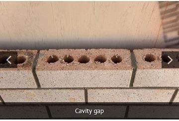
BRICK TIE BEDDING
Brick ties are required to be bedded into the brick with mortar. You need to ensure that
there is a minimum mortar cover of 15mm of the end of the tie.
There are two trade practices for the bedding of brick ties. Wet-bedding is the process
where the brick tie is held with a layer of mortar both above and below the tie. With dry-
bedding the brick tie is placed directly on top of the brick and mortar is only placed on the
top of the tie.
Tie bedding is an area of the trade where regulation has not kept up with building science.
The current acceptable solutions for tie bedding are:
On timber framing E2/AS1 requires wet-bedding
On concrete block work E2/AS3 allows for either bedding methods.
In general, bricklayers prefer to dry-bed brick ties. This is because it is a more efficient,
productive and a proven method of installation. In 2006 BRANZ released a report that
confirms that dry bedding is an acceptable procedure in brick veneer construction. You can
read a copy of this report here: BRANZ DryBeddingMasonry Ties StudyReportno156:2006

Master Brick & Blocklayers Association recommends that designers ensure they specify
dry-tie bedding until NZS4210:2001 is updated. This may mean that you will need to
identify your building consent application as an alternative solution proposal–were
commend including the above reference to the BRANZ study report.

BRICK TIE PLACEMENT
Brick veneer is not assumed to have any structural strength and relies on support from the
ties securing it to the structural timber framing. The ties themselves are designed to support
a certain tributary area of masonry and it is important that the area per tie is not exceeded.
The bottom brick tie, when the rebate is sealed with a liquid applied damp –proof course,
must be within 300mm or two courses (whichever is smaller) of the base of the veneer.
Brick ties are to be fixed to studs only with a maximum of 600mm centres horizontally and a
maximum of 400mm vertically. Ties should also be positioned within 300mm horizontally of
openings (BBFNZ recommends 200mm vertical spacing to meet the 220kg/m2 mass
requirement in any seismic zone)
Designers and bricklayers should familiarise themselves with Section 9.2.7 Wall Ties and
Tables 18A and 18B of E2/AS1. You can read this documentation here: E2/AS1 (part4)

Master Brick & Blocklayers recommend placing Brick rows of mesh in the 2 joints above an
opening that extends to 2 full units on either side of the opening, to reduce the risk of step
cracking.

Master Brick & Blocklayers Association ask that when selecting brick ties that you support
our manufacturing members:
INNOVATIVE BUILDING PRODUCTS LTD– www.brickties.co.nz

                                                                                    8|Page
Brick Bonding

The way that bricks are arranged affects a veneers stability and strength and is referred to
as a ‘bond’ or ‘bonding’.

Brick Bonds
The way that bricks are arranged affects a veneers stability and strength and is referred to as a
‘bond’ or ‘bonding’.

RUNNING OR STRETCHER BOND

Section 9.2.2 of E2/AS1 requires that bricks are laid with a ‘running bond’ (also referred to as
‘stretcher bond’. E2/AS1 (part4).

To maintain a running or stretcher bond, bricks of each course must overlap the previous course by
between 25% and 75% of the length of the bricks (NZS4210:2001 Section 1.3 Definitions).

A bond pattern should be consistent throughout the veneer.

BRICK CUTTING

To achieve a stretcher or runner bond and meet industry aesthetic standards, the minimum size a
masonry unit should be cut to is the greater of: ¼ the length of the units or the width of the units.

The practice of brick cutting should comply with the Master Brick and Blocklayer Practice Advisory –
Brick and Block cutting: https://staging5.nzmta.com/wp-content/uploads/2021/03/
practiceadvisorybrick-and-block-cutting-mbb-4.pdf

MININUM WALL OR PANEL WIDTH

Section 9.2.3 of E2/AS1 advises that no length of veneer wall or panel can be less than 230mm.

If the wall or panel turns (usually 90°) then this is usually referred to as a return. The measurement
of a return is taken as the total length of the wall rather than treating the wall as two separate
panels.

INTERNAL CORNERS

An internal corner should mirror an external corner as closely as possible. To meet industry
standards and avoid the appearance of an undersized cut masonry unit, the length of the masonry
unit visible in an internal corner should be the greater of: ¼ the length of the unit or the width of the
unit.

                                                                                             9|Page
STACKBONDING
Stackbonding provides the ability to create a brick cladding that presents both vertical and
horizontal lines and patterns that add new dimensions to the aesthetic appeal of the veneer.
Stackbonding is not recognised under the acceptable solution for brick veneers (E2/AS1) and
therefore requires specific engineering design.
To assist with the design of stack bonded systems, the New Zealand Concrete Masonry Association
(NZCMA) has released design guidance that provides the following specification and limitations for
stackbond use:
Studs are to be positioned at a maximum 400mm centers.
Screwfixed brick ties are to be installed at maximum 400mm centers horizontally and 400mm
centers vertically (every 4th course commencing at two courses above the base or equivalent in the
case of a double height brick)
In-joint reinforcement is to be installed every 4th course (or maximum of 400mm) alternating with
the rows of brick ties.
The maximum permitted height is 4.0m unless Specific Engineering Design has been undertaken to
cover the additional required height specified.
You can read this information here: NZCMA informationonstackbondingdesign
10 | P a g eBrick Laying
A good bricklayer carefully plans their work prior to laying. This involves:
Carefully reading ALL building consent documents and familiarising themselves with any
standard cited in the documents before starting,
Checking that the substrate has been properly prepared and sealed where required,
Calculating how many bricks are going to be required (and ensuring that factors such as
mortar thickness are taken into account),
Checking the bricks supplied are correct as per the building consent and contract,
Checking that there are no obvious issues/defects with the brick pallets provided,
Checking that all pallets display the same batch number
Identifying what cuts may be required.
Bricks should be laid to a straight line which generally involves running a string line at both ends of
the wall. Bricks should be buttered to form perpends (“perps”).
NZS4210:2001 sets out the following tolerances for brick veneers walls:
item toLerance
Deviation from vertical within 10 mm per 3 m of
a storey height
Deviation from vertical in total 20 mm
height of bldg.
Relative vertical displacement 2 mm on nominated fair
between masonry courses. face (one side only)
5 mm on structural face
Deviation from line in plan:
(a) In any length up to 10 m 5 mm
(b) In any length over 10 m 10 mm total
Average thickness of bed joint, +/- 3 mm on thickness
cross joint or perpend joint. specified
BRICK BLENDING
Bricks are natural products that are subject to colour variance between batches. ‘Blending’ is the
process used to vary brick pallets as they are laid as a means of avoiding any unwanted patterns
caused by a variance.
Master Brick & Blocklayers recommends that bricklayers select bricks and blend vertically from at
least three pallets in order to achieve an adequate colour mix.
A bricklayer should also regularly check the veneer while laying from a viewing distance of 6.1m for
obvious pockets of colour forming that may be unacceptable.
11 | P a g eWeep Holes & Vents
Air flow and drainage are essential design features that ensure dry homes.
Weep holes and Cavity Ventilation
Weep holes and vents are components of brick design intended to assist with drainage and airflow
within the brick cavity.
WEEP HOLES
It is important to remember that while brick veneers are an excellent rain shield, they are not
waterproof. A considerable amount of water would be required before moisture is likely to flow
down the back of the veneer.
In the event that this saturation does occur, a series of gaps or ‘weep holes’ are required to be
placed along the bottom course.
A weep hole of 75mm x 10mm is required to be placed every 800mm along the base or alternatively
1000mm2/linear meter of wall.
Any weep hole wider than 13mm requires vermin proofing.
Weep hole requirements also need to be met across the heads of doors, windows and openings.
VENTS (VENTILATION)
Ventilation is the process of replacing air in any space with the intention of improving air quality. For
the brick cavity this means replacing moist air within the cavity with drier air from the outside.
E2/AS1 provides two acceptable methods for venting brick veneer:
Vertical vents installed as per the earlier weep holes in the top course or 2nd course down,
or;
Leaving a 5mm gap around the top of the veneer.
You can view these E2/AS1 requirements in Section 9.2.6(d) and Figure 73E here: E2/AS1 (part4).
Vent holes are not generally required under window sills as air can move freely around the frame.
12 | P a g ePLASTERED OR PAINTED BRICK VENEER
Where a brick veneer is plastered or painted, the brick veneer exterior cladding is effectively a
waterproof system. This means the need to have air circulation to dry the cavity and the weep holes
to drain the veneer become less important.
The acceptable approach to weep holes in this scenario is 50mm x 10mm weep holes at 1m centres
or 500mm2/linear meter of wall.
Vent holes are still required at the top of the plastered or painted veneer however designers should
check with their local council as requirements vary.
Master Brick & Blocklayers ask that when selecting vents that you support our members: Victor
Vents: http://www.victorvents.co.nz/
13 | P a g eBrick Veneer Flashings
It is the bricklayer’s responsibility to ensure that all flashings have been correctly installed prior to the
bricks being laid.
Brick veneer flashings
A flashing is an impervious material designed to prevent water from entering the brick cavity from
joints such as those found in windows and doors.
The brick veneer system has functioned in New Zealand very successfully for many years with
minimal flashings being installed; however, in the modern environment, flashings are an essential
part of any cladding systems.
Designers and bricklayers should familiarise themselves with Figure 73 Cof E2/AS1 which can be
viewed here: E2/AS1 (part4)
It is the bricklayer’s responsibility to ensure that all flashings have been correctly installed prior to
the bricks being laid.
HEADFLASHINGS
If a metal head flashing is used and fixed to the framing, you should ensure it is kept 5mm short at
each end and the ends of the flashing should be turned up. This will allow for any movement in the
framing without interfering with the bricks.
A 5-10mm gap between the underside of the lintel bar and the flashing allows for both drainage and
ventilation eliminating the need for weep holes in the bricks across the head of the opening.
JAMB FLASHINGS
Jamb flashings are simple and inexpensive. Use a 200mm wide polyethylene flashing, tucked into
the joinery flange. The open end of the flashing is to be held off the building wrap using a kick-out
batten or protruding clouts. The junction between the bricks and the joinery does not need to be
sealed.
SILL FLASHINGS
Any moisture being driven up the sill brick needs to be stopped from reaching the timber framing
and redirected into the bottom of the cavity. NZS 3604S11.7.7 requires that flashings be extended
200mm past the sides of any openings where practical to do so.
14 | P a g eBrick Sills & Lintels
Designing and Constructing Brick Sills and Lintel Bars
BRICK SILLS
Brick sills must overhang the brick work below by 30 - 50mm with a minimum slope of 15 degrees.
Bricks must be evenly spread and of equal thickness across the width of the sill.
Another option is to have a header course spread evenly over the sill width. This applies to the heads
of the windows as well.
LINTEL BARS
A lintel bar is a load-bearing building component that spans across openings such as windows and
doors to provide structural support.
Designers and Bricklayers should familiarise themselves with Paragraph 9.2.9 and Table 18D and
Table 18E of E2/AS1. You can read this here: E2/AS1 (part 4).
Lintel seating – lintels shall have a minimum seating into adjacent veneer of
(i) 100mm for spans up to, and including 2m
(ii) 200mm for spans over 2m
There are two methods of installing a lintel bar with brick veneer:
Acceptable solution for lintel bar – E2/AS1 provides a method where the angle spans the brick from
one side to the other. The lintel should be kept either solely in the brick or the timber framing but
not both. The angle sizes within Table 18E of E2/AS1 should be applied.
Alternative solution for lintel bar – The second method involves sitting the lintel back 20mm from
the face of the veneer, and have correct seating. With this method, the angle is attached directly to
the structure and kept 5mm short of the opening at each end to accommodate any movement in the
frame. The below table applies to this method.
Master Brick & Blocklayers suggest that as the sizes specified in Table 18E are the minimum
requirement, increasing the size (thickness) where issues could develop (eg: wider openings, heavy
units, signifacnt height to carry).
15 | P a g eMax.Span (mm) Size of Angle
3000 mm 80 x 80 x 6
3500 mm 100 x 100 x 6 or
125 x 75 x 6
4500 mm 125 x 75 x 8
4800 mm 125 x 75 x 10
The durability requirements for lintel bars can be seen in Table 18D of E2/AS1 (part 4).
16 | P a g eControl Joints
Control joints allow concrete brick veneer to respond to minor movement of the building.
Control Joints
Buildings and building components generally move slightly after construction. Often this relates to
normal expansion due to acceptable moisture absorption. Control joints are vertical gaps, usually
filled with in elastic materials, which allow brick veneer to respond to these movements usually by
opening in response to expansion.
Generally clay brick veneer does not require control joints. Slight expansion can occur soon after
manufacture but this does not appear to present any issues in normal construction.
Concrete brick veneer however typically requires control joints. Designers and bricklayers should
check manufacturers’ specifications and familiarise themselves with Section 9.2.8.2 of E2/AS1 which
you can read here: E2/AS1 (part4).
DESIGNING OF CONTROL JOINTS
Control joints should also be designed and constructed as shown in Figure 73A of E2/AS1.
This requires that control joints consist of:
A backer rod of compressible foam; and
Sealant that complies with either Type F, Class 20 LM or 25 LM of ISO11600 or Low modulus
Type II Class A of Federal Specification TI-S-00230C
PLACEMENT OF CONTROL JOINTS
To allow for the potential shrinkage in the length of concrete brick veneer E2/AS1 requires that
vertical control joints are placed at not more than 6m centres.
Vertical control joints are also required to be located:
Within 600mm of T joints;
Within 600mm of L shaped corners or by restricting the space to the next control joint to
3.2m maximum
At changes in wall height that exceed 600mm;
At changes in wall thickness.
17 | P a g eIt is not uncommon to read reports from Geo-Tech Engineering control joints in clay brick veneers
due to expansive clay soils but this is not necessary. Where such soil types occur an appropriate
foundation should be designed to manage this and there is no evidence that control joints would be
necessary.
Control joints should be considered however in clay and concrete brick veneer in the following
circumstances:
If a wall is 10m or longer and has no window or door openings– a control joint should be
installed at an intermediate point.
Where a small panel of brick work adjoins a large panel of brickwork, as movement within
the framing may cause a crack, a control joint may be considered. An alternative however
would be to strengthen the framing using additional brick ties and using reinforcing in
mortar joints in these areas.
Where a control joint is used it is important to ensure that the framing details provide a stud within
200mm of each side of the joint for the fitting of brick ties.
If possible, position a control joint behind down pipes to hide them.
It is important to remember that if a crack develops in an otherwise well-constructed brick veneer it
is an aesthetic issue only and should cause no problems as to weather tightness or the overall
integrity of the veneer. A control joint is in effect a controlled crack.
18 | P a g eBrick Veneer Heights
Brick Veneer Heights
E2/AS1 sets the limitations for Brick Veneer heights in Section 9.2.3 and Figure 73B . You can read
this document here: E2/AS1 (part 4)
It advises that brick veneers with timber framing shall have:
A maximum height of veneer above finished ground level of 7m;
A maximum height of 4m from the foundation;
A maximum height of 5.5m to the apex of a gabled area.
If the veneer is supported by a masonry structure, NZZS4229:2001 permits a veneer height of 6.0 for
the wall and up to 10m in a gable area.
The Clay Brick and Paver Manufacturers Association have developed a combined 2 storey system for
clay brick veneer- Design Note TB 1. Designers and Bricklayers should familiarise themselves
with this document which you can read here: 2StoreyClayBrickVeneerConstruction- MadeEasy
You may also want to consider the following concrete brick 2 Storeys olutions:
Firth 2StoreyBrickVeneersolutionforDevonstoneand70mmBrickVeneers
Firth 2StoreyBrickVeneersolutionforFirth 10seriesHollowMasonry, Manorstoneand 90mmBrick
Veneers
19 | P a g eBrick Staining
Staining generally has only an aesthetic effect on brick veneer.
Stain removal
While it is perfectly normal for clay bricks to have a slight variance in colour, this is different than
brick stains. All care should be taken during construction to prevent staining occurring, however this
is not always possible.
Stain removal depends on the cause of the stain.
Master Brick & Blocklayers recommends that you consult your bricklayer or brick supplier before
attempting stain identification and removal.
VANADIUM STAINS
Light-coloured clays often contain vanadium salt that are generally colourless but under certain
conditions may appear as yellow, green or reddish-brown discolouration of the brick. Vanadium
stains are neither permanent nor harmful and do not indicate a defect in the brick.
Vanadium stains are often generated by the use of too strong a concentration of hydrochloric acid
during the initial cleaning process, or from excessive water penetration.
While vanadium stains will wash off overtime, an application of 4% Sodium Hypochlorite (Janola) or
a mixture of Sodium Bicarbonate and water (60g per litre of water) will assist in their removal.
Hydrochloric acid may turn vanadium salts black and make it difficult to remove. It is therefore
important that vanadium salts are removed before attempting to clear mortar residue from clay
brick veneer with hydrochloric acid.
MANGANESE STAINS
This stain occurs characteristically along the edges of grey or brown clay bricks. It appears as a dark-
blue brown discolouration.
If you suspect manganese staining, contact your brick company for them to inspect and advise on a
resolution.
20 | P a g eCOPPER AND BRONZE STAINS
Sometimes clay brick veneer may be in close proximity to metals such as copper or bronze. Water
washing over these metal surfaces can result in a bluish-green stain appearing on the surface of the
bricks.
These stains may be removed using a solution of 1 part acetic acid (80% or stronger): 1 part
hydrogen peroxide (30%-35%strength):6 parts water.
IRON OXIDE (RUST)
Rust can be the result of using hydrochloric acid on clay bricks. This may be able to be removed by
applying a solution of 1 part phosphoric acid to 4 parts of water. Allow up to 24 hours for it to work.
SMOKE STAINS
Common around domestic fireplaces but can also be an issue with fire damaged buildings. Minor
smoke stains can be removed with sugar soap–which is a highly alkaline mixture. Mix
approximately 500g in to 2 litres of water and apply liberally by brush. After the smoke stains
disappear, scrub with a mixture of detergent and household scouring powder containing Sodium
Hypochlorite (Janola).
21 | P a g eEfflorescence
Efflorescence
Efflorescence is a calcium deposit that can form on clay or concrete veneer. It appears as a white
powdery and sometimes ‘fluffy’ deposit on the brick.
Efflorescence occurs where excessive amounts of water enters a veneer that has soluble salts present.
When the water dries out, the salts are then deposited on the surface of the veneer. Soluble salts
can enter the veneer from various sources:
Mortar components, particularly cement.
Soil or fill in contact with the wall.
Sea spray in coastal areas.
Masonry units (not a common source).
Master Brick & Blocklayers recommends that bricklayers protect new brick work with adequate
coverings when rain interrupts construction.
Persistent efflorescence may act as a warning sign that water is entering the wall through faulty
copings, flashings or pipes.
CLEANING EFFLORESCENCE
Most efflorescence will naturally disappear over time, however its removal can be accelerated by
brushing with a stiff dry brush. The use of a dust pan or vacuum cleaner to collect the salts after
22 | P a g ebrushing is recommended as this will prevent salts from re-entering the brickwork or any porous
paving materials below.
After brushing and cleaning up, an absorbent cloth (wrung out until damp only) can be used to pick
up any residue. Frequent rinsing of the cloth in fresh water is advisable. Rinsing brick work with
water will only cause the salt to be re-absorbed in to the bricks and reappear when dry.
Brick Tolerances and
Aesthetic Appearance
Brick Tolerances and Aesthetic Appearance
It is possible for a brick veneer to be building code compliant but not have the visual look that
reflects the skills of an experienced bricklayer. This is referred to as ‘workmanship quality’.
It is important to discuss with your bricklayer the aesthetic look you are hoping to achieve with your
brick veneer and if possible, include them in your selection process.
Master Brick & Blocklayers recommends that parties to a brick veneer construction enter into a
clear, written contract that sets out the expectations of parties including agreed workmanship
quality standards, quality checking responsibilities and an agreement on how disputes will be
managed– even if it is not a compulsory requirement under legislation.
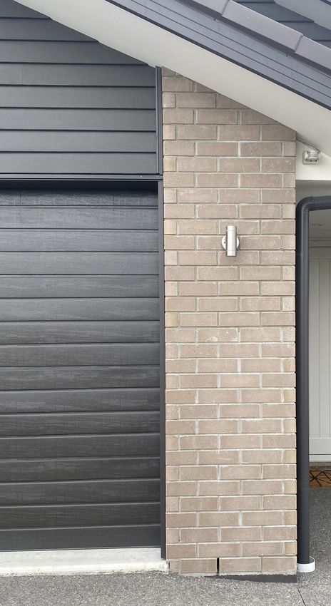
VIEWING DISTANCE
Due to the nature of bricks no two bricks are the same and no brick is perfect when examined
closeup. ASTMC90 has been adopted as the industry standard for viewing brickwork – it states that
‘for exposed wall construction chips and imperfections shall not be evident when viewed from a
distance of not less than 6.1m in diffused light’.
DRYING CRACKS
During the manufacturing process hairline cracks can appear in a small number of clay bricks. This
occurs during the drying process when excess moisture is removed from the clay prior to it entering
the kiln. Bricks with these cracks conform to AS/NZS4455 and do not compromise the structural
integrity or weather tightness of the brick.
From an aesthetic standpoint, the relevant American Standard Test Method (ASTM) has been
adopted. ASTM C216-04 specifies that bricks must contain less than 5% visible cracking when viewed
from a distance of 6.1 meters.
CHIPPING
Bricks may be transported several times before arriving onsite and occasionally chipping can occur.
Chips are more noticeable on bricks that have a surface colour different from the body of the brick.
A workmanship quality standard is achieved if imperfections, including chips, are not visible when
viewed from a distance of not less than 6.1m under diffused light as per ASTM C90.
New Zealand does not have a standard to assist a Bricklayer to evaluate the level of chipping
acceptable in a brick prior to laying however ASTM C216-15 has been adopted by BBFNZ.
23 | P a g e ASTM C216-15 for a general purpose face brick (FBS textured) basically has the following
requirements:
Chips from the edge should not be deeper than 8mm
Corner chips should not be deeper than 13mm.
When all the length of the chips are added up that the total is not exceed 10% of the
perimeter of the brick face (as an example, the accumulative lengths of the chips for a
230mm X 75mm brick shall not exceed 61mm).
It is good practice for Bricklayers to set aside bricks that do not meet this standard and to assess
whether to discard it or use it for cuts.
DIMENSIONAL CATEGORY
AS/NZS4455 Masonry units and segmental pavers’ calls for bricks to be classified into dimensional
categories based on their deviation from their work size, or the size specified in manufacture.
To test if bricks meet the standard, 20 bricks should be placed in a row and the total length should
be measured. This can be done with height, width and length. Tolerances for these are:
RUBBING
During transportation brick may rub together on the pallet. This can sometimes cause light rubbing
on the face of the bricks. Excessively rubbed bricks should be discarded or used for cuts.
COLOUR VARIATION
Clay and concrete bricks are both subject to some variation in colour between batches. This is part
of the inherent beauty of brick.
Unusual discolouration patterns can be limited by blending the bricks. Should there be any concern
regarding significant colour variation laying should cease and the manufacturer contacted.
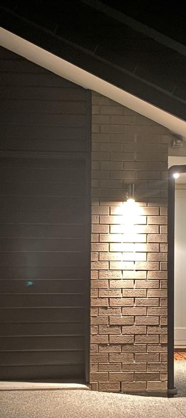
24 | P a g eCritical Lighting
GUIDANCE – GUIDE TO TOLERANCES, MATERIALS AND WORKMANSHIP IN NEW RESIDENTIAL CONSTRUCTION 2015
Unless speci cally outlined in the contract It is common practice to use high output lighting
speci cations, imperfections that are only visible to accentuate areas requiring attention during the
under critical light do not indicate defective construction phase, but this level of lighting is not
workmanship. suitable for performing a subjective visual
inspection of interior surfaces.
Critical lighting occurs when sunlight or an intense
arti cial light source strikes a wall or other at More information on critical lighting and its effects
surface at a low angle, typically 15° or less. is available from:
Because of the low angle of the light any small
variations or irregularities on the surface cast a > AS/NZS 2589:2007 - Gypsum linings - Application
relatively large shadow which can highlight and nishing (particularly Appendix C)
imperfections that would not normally be visible > AWCIANZ Trade Guidelines and Information
under more diffused lighting conditions. Booklet Oct 2012 (www.awci.org.au/national-
publications/ trade-guidelines-information-
Critical lighting occurs naturally for a short period booklet )
each day, typically 30–60 minutes in the early
morning and late afternoon when the sun is low in > AWCIANZ Insight Newsletter: Critical light
the sky. August
2014 (awci.org.nz/critical-light/
Diffuse light is light that is scattered, causing it to fall on the crop from all sides. The light is evenly
distributed, leaving no sharp shadows. Diffuse light arises when direct light is scattered naturally (e.g.
by clouds) or with artificial means (e.g. a diffuse coating).
Direct light is a light where no obstacle is between the light source and the subject. The light rays all
go in the same direction and are completely rectilinear from their point of departure to their
destination.
On the contrary, diffuse light is a light whose light rays go in different directions.
25 | P a g eBricks Slips
eeexcet
GUIDANCE FROM - CLAY BRICK & PAVERS
ASSOCIATION NZ MANUFACTURERS
Introduction
What is a brick slip? We like to refer to a brick slip as the solution to achieving the genuine look of
clay brick virtually anywhere you wish to put brick. It is a piece of brick approx 18mm thick, cut from
the face of a brick using a diamond saw; glued to a substrate as you would for a ceramic tile.
The thickness of the brick slip is important. It should be a minimum of 15mm, and a maximum of
25mm, the optimum being 20mm; stone slips are thicker. There are four basic reasons for this
requirement: to keep the weight to a minimum; to provide a smooth surface (free of the holes) upon
which to spread the glue; to avoid forming a pocket that can trap moisture that could freeze in the
winter or boil in the summer creating possible problems; and to have sufficient thickness to achieve
a suitable mortar joint.
Cutting Brick Slips
It is desirable to cut the brick slips on site. The advantages of doing this are: that you know the slips
have come from the same batch number as other bricks on the job; wastage is kept to a minimum;
and there are no breakages due to transport. There are approx. 50 brick slips per square metre of
wall. The slips may be cut as stretchers, headers and even right-angle slips (L-shape) to go around
corners, and use up the sides of windows. If the brick is a rumbled brick add approximately 3mm to
the thickness of the cut to allow for the rumble.
Installation
The brick slip system is an excellent system, provided all involved follow the specifications, of which
there are three components involved: the brick slip itself; the substrate it is going on; and the
adhesive used. If the installation is not carried out correctly there is a high risk of failure, which could
be very expensive to repair.
The Brick Slip
Cut the brick slips to the required thickness; 20mm recommended.
Ensure the slips are dry prior to installing them.
Remove all dust from the back of the slip with a damp cloth, prior to applying adhesive. The
Substrate
If the substrate is concrete panels or concrete blocks, movement control joints need to be installed
through both the concrete substrate and the brick slips that are adhered to the surface.
PLEASE NOTE: Over recent years some major manufacturers/suppliers of fibre-cement board
products have withdrawn their approval for brick slips to be installed on their products. It is
important that approval is obtained from any supplier/manufacturer of a fibre-cement board as to
its suitability as a sub-strait for brick slips prior to proceeding with design and installation.
The Adhesive
Although there are several good adhesives on the market we recommend one of the following:
http://www.flexconz.co.nz
26 | Pwith
Wall' n Floor marketed by Flexco (NZ) Ltd (09) 268 6970. They have an excellent website age
full instructions www.flexco-nz.co.nz.Laticrete NZ provide a full instruction sheet for fixing brick slips using the Laticrete System; the
following are the major points covered in these instructions.
Substrate Surface Preparation
IMPORTANT: If the substrate is precast concrete, it is essential that all 'releasing agents' have been
thoroughly removed from the concrete prior to commencing laying brick slips and that all brick
dust has been washed off the brick slip.
The surface must be clean, dry and free of contaminants. No primer is required, the
waterproof membrane Laticrete Hydro Ban water proofing and crack prevention membrane
provides a barrier.
Seal all joints by using a brush or roller to apply a thick coat of Laticrete Hydro Ban to a strip
75mm either side of the joint.
Immediately bed the reinforcing fabric bandage into the wet liquid to bridge the joint.
Coat the remainder of the wall with Laticrete Hydro Ban, and at the same time apply a
second liquid coat over the reinforcing bandage. Note: 5 litre bottle covers 10m2; drying
time approximately 12 hours.
Applying the Brick Slip Adhesive
By just mixing with Laticrete 254 Platinum powder will make a high strength flexible and shock
resistant latex thin-set adhesive – coverage 7.4 – 8.8m2 per 23kg bag using 6mm x 6mm notched
trowel.
Mix 5:2 litres of fresh water with 23kg bag of Platinum. Mix until creamy and workable.
Adjust quantity of liquid to achieve the proper working consistency.
Allow to stand for 5–10 minutes and re-mix.
Using the edge of a trowel, scrape a film of adhesive, working it into the substrate. Apply the
adhesive to the back of the brick slip with the trowel, working it into the surface. It is
essential that sufficient adhesive is used to completely cover the back of the slip with a
minimum 2.5–3.0mm thick uniform adhesive bed.
Place the brick slips while the adhesive is wet and tacky. Take care to firmly bed the brick
slips onto the wall substrate.
If mortar is being applied at the same time as the adhesive, bricks may be pointed as the job
progresses. In other words, laid the same as if laying normal bricks. I recommend this
method. If not, joints may be pointed once the adhesive has firmly set. Note 10mm spacers
are required if this method is adopted.
General Comments
It is not essential but we recommend a waterproofing product (Surfapore R) be applied over
the wall surface once dry and completed, for extra protection.
It is essential that control joints be installed where brick slips abut a different cladding,
either horizontally or vertically or as required.
PLEASE NOTE:
The CB&PMA and its members take no responsibility for the installation of brick slips; the
information provided here is done so as a guide for our customers, and to aid the process of
installing brick slips. It is the responsibility of the owner, the builder, the bricklayer and the
architectural designer to ensure that acceptable and correct procedures are followed and carried
out by professional who know what they are doing.
27 | P a g eYou can also read