Stretchable Tattoo-Like Heater with On-Site Temperature Feedback Control
←
→
Page content transcription
If your browser does not render page correctly, please read the page content below
micromachines

Article
Stretchable Tattoo-Like Heater with On-Site
Temperature Feedback Control
Andrew Stier 1 , Eshan Halekote 1 , Andrew Mark 1 , Shutao Qiao 2 , Shixuan Yang 2 ,
Kenneth Diller 3 and Nanshu Lu 1,2,3,4, *
 1   Department of Electrical and Computer Engineering, University of Texas at Austin, Austin, TX 78712, USA;
     andrewcstier@gmail.com (A.S.); ehalekote@gmail.com (E.H.); andrewemark@gmail.com (A.M.)
 2   Center for Mechanics of Solids, Structures and Materials, Department of Aerospace Engineering and
     Engineering Mechanics, University of Texas at Austin, Austin, TX 78712, USA;
     shutao2011@gmail.com (S.Q.); rock002008@gmail.com (S.Y.)
 3   Department of Biomedical Engineering, University of Texas at Austin, Austin, TX 78712, USA;
     kdiller@mail.utexas.edu
 4   Texas Materials Institute, the University of Texas at Austin, Austin, TX 78712, USA
 *   Correspondence: nanshulu@utexas.edu; Tel.: +512-471-4208

 Received: 20 February 2018; Accepted: 27 March 2018; Published: 8 April 2018

 Abstract: Wearable tissue heaters can play many important roles in the medical field. They may
 be used for heat therapy, perioperative warming and controlled transdermal drug delivery, among
 other applications. State-of-the-art heaters are too bulky, rigid, or difficult to control to be able to
 maintain long-term wearability and safety. Recently, there has been progress in the development of
 stretchable heaters that may be attached directly to the skin surface, but they often use expensive
 materials or processes and take significant time to fabricate. Moreover, they lack continuously
 active, on-site, unobstructive temperature feedback control, which is critical for accommodating the
 dynamic temperatures required for most medical applications. We have developed, fabricated and
 tested a cost-effective, large area, ultra-thin and ultra-soft tattoo-like heater that has autonomous
 proportional-integral-derivative (PID) temperature control. The device comprises a stretchable
 aluminum heater and a stretchable gold resistance temperature detector (RTD) on a soft medical
 tape as fabricated using the cost and time effective “cut-and-paste” method. It can be noninvasively
 laminated onto human skin and can follow skin deformation during flexure without imposing any
 constraint. We demonstrate the device’s ability to maintain a target temperature typical of medical
 uses over extended durations of time and to accurately adjust to a new set point in process. The cost
 of the device is low enough to justify disposable use.

 Keywords: epidermal electronics; wearable heater; temperature sensor; feedback control

1. Introduction
     There exists a need for soft, stretchable electronic heating devices that can conform to human
skin unobstructively and stay attached during long term use. Such devices can serve a variety of
applications in the medical field. As some examples, heat is commonly used in physical therapy
following exercise-induced delayed onset muscle soreness (DOMS) [1,2]. Heating injured joints can
induce thermal expansion of the collagen tissue and thus reduce pain and stiffness [3–5]. When
hypothermia occurs due to anesthesia [6], applying heat to the palms and soles of a patient with
distended blood vessels can re-warm the body’s core temperature [7,8]. Applying heat over a skin
surface can accelerate the transdermal diffusion of chemicals from a drug patch [9,10].
     Conventional heaters used to treat muscle pain or joint injuries include electric heat packs [11]
and heat wraps [12]. Heat packs do not have very controllable temperature and are heavy and bulky.

Micromachines 2018, 9, 170; doi:10.3390/mi9040170                       www.mdpi.com/journal/micromachines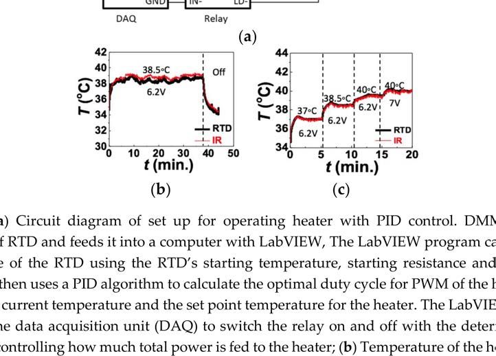
Micromachines 2018, 9, 170                                                                           2 of 14

Heat wraps are easier to control but are also heavy and their rigidity makes it difficult for them to
be worn seamlessly [5]. These products’ inability to conform well to skin [13–15] make them less
comfortable and also present a more severe problem—lack of uniform and consistent adhesion to the
skin surface could lead to air gaps which cause hotspots [16]. These hotspots could burn the skin if the
heater is operated near the safety threshold of 43 ◦ C [17]. This can severely limit the range and thus
the effectiveness of the conventional heaters.
      One heating method that can safely heat the body at temperatures close to 43 ◦ C and the current
gold standard for preventing the hypothermia caused by anesthesia, is forced air warming. Forced air
warming heats air and pumps it into blankets covering large portions of the patient. While effective at
raising the core body temperature, forced air warming has some disadvantages including bulkiness,
obstructiveness to surgeries and high cost [18,19].
      Recently there has been an expansion of the development of stretchable electronics [20–23].
Methods that have been used to produce these type of electronics include embedding carbon
nanotubes (CNTs) in elastomers [24,25], depositing silver (Ag) nanoparticles in polyeruthane [5,26],
chemically bonding Ag flakes to CNTs [27,28], combining Ag nanoparticles with elastomeric fibers [29],
electrospinning Ag nanofibers onto a flexible substrate [30], constructing CuZr nanotrough networks
that function as stretchable electrodes [31], constructing stretchable gold (Au) electrodes from
multi-layers of Au nanosheets [32] and patterning metal thin films into serpentine [33,34] or fractal
shapes [35,36] to minimize their strain during stretching. This last method has enabled the creation
of epidermal electronics—ultrathin, ultrasoft electronics, physiological sensors, and electrical and
thermal stimulators—that can adhere and conform to skin surfaces and bend and stretch without
breaking, detaching, or imposing any mechanical constraint to the skin [36–38].
      With the development of stretchable electronics, stretchable patch heaters have emerged in recent
years. Examples include joule heating devices fabricated from soft Ag nanowire composites [5,30,39],
copper (Cu) nanowire based fabric [40], stretchable copper zirconium electrodes [31], or stretchable
Au serpentines [6,11,29,32]. Using a stretchable and conformable heater could solve the major
disadvantages of conventional solid heaters. However, the existing stretchable heaters involve
expensive nanomaterials or time-consuming procedures to produce. Moreover, most of them have
no method of acquiring temperature feedback from the heater as they are not equipped with any
temperature sensors. As a result, most of the reported stretchable heaters do not use temperature
feedback to autonomously maintain a set temperature for the heater. One of the exceptions is a
wearable fabric heater described by Cheng et al. [40]. This heater is loose enough that it is able to use
an unspecified temperature sensor to monitor and control the heater. Of the more tightly conformable
heaters, one with temperature feedback only has the functionality of turning the heater off if it gets too
hot—aside from that, the temperature feedback is not used to actively control the heat of the heater [9].
The best existing example of a tightly conforming stretchable heater with continuous feedback control
is the metal nanofiber heater developed by Jang et al. [30]. This heater uses a thermistor placed on the
outer edge of the heater to detect the heater’s temperature and uses an unspecified control algorithm to
keep the heater at a specified temperature. This set-up relies on the assumption that the temperature at
the outer edge of the heater is representative of the temperature of the heater overall but the heat profile
across the heater is not actually uniform. Moreover, the thermistor appears to introduce disturbances
in the uniformity of the heater.
      In other stretchable heaters with temperature sensors, the temperature sensing element is the
same as the heating element [9,15]. The biggest disadvantage of this setup is that the dual-purpose
element is measuring its own temperature instead of the actual skin temperature. The closest example
of a stretchable heater with separate, unobstructive temperature feedback is one developed for a
prosthetic hand but not tested on human skin, where a multilayer heater and sensor array is laminated
onto a prosthetic hand [41]. Without the use of effective temperature feedback, past stretchable heating
devices have relied on the relationship between voltage and heat generated in order to maintain the
heater at a desired temperature. However, heat transfer conditions vary from person to person and
Micromachines 2018, 9, 170                                                                         3 of 14

it is inaccurate to assume a consistent relationship between voltage and temperature if you wish to
apply the same heater to multiple subjects. For example, changes in blood flow can cause changes in
epidermal skin temperature [7].
       Our group has developed a “cut-and-paste” method [42], in which stretchable patterns are
cut out of ultrathin metal-polymer laminates and pasted to an adhesive substrate, allowing for
cheaper, quicker and greener fabrication of tattoo-like sensors. This method also allows for
easy integration of independent heaters and resistance temperature detectors (RTDs) on the same
substrate. Using this method, we herein present an inexpensive, easy to fabricate and power-efficient
programmable tattoo-like heating device which comprises a stretchable resistive heating element (RHE)
of serpentine-shaped aluminum (Al) ribbons and a stretchable RTD of serpentine-shaped Au ribbons.
The RTD is thin enough to not disturb the uniformity of the heat from the heating element. Included
with this device is a customized proportional-integral-derivative (PID) control software which uses
real time temperature feedback to control the heater and can maintain it at a target temperature over a
large area of skin for extended periods of time.

2. Materials and Methods
      The “cut-and-paste” manufacturing process of the stretchable tattoo-like heater is illustrated in
Figure 1a, and a picture of the as-fabricated sample on 3M Tegaderm tape is offered in Figure 1b. As
depicted in the first row of Figure 1a, the process began with placing a blanket 7 µm/13 µm Al/PET
bilayer laminate (Neptco Inc., Pawtucket, RI, USA) smoothly on a thermal release tape (Semiconductor
Equipment Corp., Moorpark, CA, USA) with Al facing up. A Silhouette mechanical cutter plotter was
programmed to cut the designed seams on the bilayer within 3 min. Excessive Al/PET was removed
once the thermal release tape (TRT) was heated and the remaining Al/PET ribbon was printed on
a 3M Tegaderm tape with the Al side facing the Tegaderm and the bluish PET side facing outward.
The 13-µm thick PET layer allows for increased mechanical integrity [43] and electrical insulation.
The same process was repeated to cut and paste the stretchable RTD ribbon, which was made out of
100 nm/15 nm/13 µm Au/Cr/PET laminate, with the PET facing the Tegaderm and the Au facing
outward, as illustrated by the second row of Figure 1a. This arrangement resulted in two layers of
insulation between the Al RHE and the Au RTD at locations where the two intersected. Both the RHE
and the RTD were cut into serpentine ribbons, which contributes to the stretchability and softness of
the device. Specifically, the stretchability and softness of these serpentine ribbons can be maximized by
fabricating their width to be as narrow as possible [37]. Due to the resolution of the Silhouette cutter,
all ribbon widths were fixed to be 400 µm [42]. Although the resolution is far from photolithographic
patterning technologies, the cost of time, materials and facilities is significantly reduced using the
freeform cut-and-paste process because it does not require any chemicals, photomasks or cleanroom
facilities. Moreover, while photolithographic process is limited to wafer scale, the patterning area of
the cutter plotter can be as large as 30 cm. wide and a meter long.
      Costs of previous epidermal electronic systems are dominated by fabrication processes such as
spin coating, photolithography, wet and dry etching and transfer-printing. These methods require
expensive clean-room fees and chemical purchases and they are also very time intensive. Using the
“cut-and-paste” method allows for the fabrication of the presented device without any of those costs,
making it significantly more cost effective than other similar epidermal electronics [38,42,44,45].
      Finally, an ultrathin, ultrasoft double-sided tattoo adhesive was laid on top of the RHE and the
RTD, providing a final layer of electrical insulation as well as increased adhesion between the skin
and the patch. Snap button connectors were used to connect lead wires to both the RHE and the RTD
(Supplementary Information, Figure S1).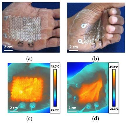
Micromachines 2018, 9, 170                                                                                  4 of 14

     Figure 1. (a) Fabrication process used for heater and resistance temperature detector (RTD), shown for
     heater. Material is put on the thermal release tape (TRT) and cut with Silhouette cutter. TRT is heated,
     excess material is removed and remaining material is transferred to Tegaderm; (b) Complete device on
     tegaderm. Aluminum with blue polyimide backing forms the resistive heating element while Au/Cr
     100/10 nm forms the resistance temperature detector.

      The palm of a human subject’s hand was chosen for the location to test the device on. The
palms of the hand are glabrous skin surfaces, and heating them along with the soles of the feet can
efficiently warm the body during anesthesia [7,8]. Presenting that the heater works effectively on
the palms of the hand therefore demonstrates that perioperative warming is a feasible application of
this device. When attached to the skin, this device conformed to the skin and deformed alongside it
without mechanical resistance, as evidenced by Figure 2a,b. When a DC voltage of 5.1 V was applied
across the Al RHE, it supplied an even amount of heat over the palm around the target temperature
of 40 ◦ C. There was minimum change in temperature during severe skin deformation such as hand
clenching, as demonstrated by Figure 2c,d, which were taken by an infrared (IR) FLIR T620 camera
(FLIR, Wilsonville, OR, USA). The University of Texas at Austin IRB protocol number for the human
subject experiments was 2010-03-0050.
      To calibrate the RTD, it was placed on an insulated hot plate and its resistance was compared
against the temperature readings of two custom made type T thermocouples. The RTD exhibited the
expected linear relationship [15] between resistance and temperature with a temperature coefficient of
resistance (TCR) of 0.0025 ◦ C−1 (Supplementary Information, Figure S2). To obtain the TCR under
service condition, calibration of the RTD was also conducted on skin together with the RHE, and an IR
camera was used for temperature measurement. In this set-up, the heat comes from the RHE instead
of the hotplate and the RTD is in intimate contact with the actual heat sink—the skin. Due to these
differences, we hypothesized that the TCR would be different from that measured on the hotplate. A
schematic of the calibration set-up is depicted in (Figure 3a). The RHE was linked to a DC voltage
supply (Mastech Linear Power Supply HY1803D, Pittsburgh, PA, USA) while the RTD was connected
to a digital multimeter (DMM, NI Elvis II). Resistance readings were logged using the DMM and
LabVIEW 2014. The device was covered with a fine layer of Johnson’s Baby Powder to control its
thermal radiation emissive properties [46]. The DC voltage supply was set to different voltages and
the temperature and resistance of the RTD were measured simultaneously using the IR camera and the
DMM, respectively. Temperature readings from the IR camera were logged using FLIR Tools+.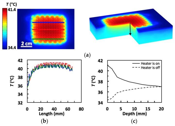
Micromachines 2018, 9, 170                                                                                 5 of 14

     Figure 2. (a,b) Device conforms to hand and maintains its conformability during opening and closing;
     (c,d) Infrared (IR) images of the device powered with proportional-integral-derivative (PID) control as
     the hand is opened and closed. The PID controller automatically adjusts power output so the hand
     does not overheat when it closes.

      Figure 3. (a) Circuit diagram of set-up for calibration of RTD in situ. Heater is brought to different
      temperatures by adjusting Vin. Resistance and temperature are measured simultaneously using a
      digital multimeter (DMM) and IR camera, respectively; (b) Lateral heat distribution of heater. Blue,
      red and green lines on IR image mark the horizontal line across which temperature was measured for
      their respective red, blue and green plots. Temperature distribution is fairly uniform. Dotted purple
      line on IR image shows area that the IR camera calculated the average temperature for; (c) Average
      temperature of area marked by the dotted purple line in Figure 3b (top) and resistance of Au/Cr RTD
      as measured by DMM (bottom) each plotted across time as Vin was changed to 3.8 V, 4.5 V and finally
      5.1 V; (d) The calibration curve for the RTD: ∆R/R0 of the RTD versus ∆T of the average temperature
      of the area around the RTD as marked by the dotted purple line in Figure 3b. The calibration constant,
      β, is marked and is equal to 0.000203.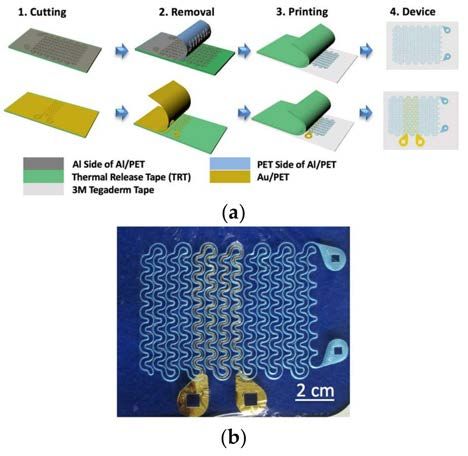
Micromachines 2018, 9, 170                                                                           6 of 14

      For safety purposes, the RHE-RTD calibration was first carried out on a glass slide, which has
thermal properties similar to those of human skin [17]. The TCR was measured to be 0.0022 ◦ C
(Supplementary Information, Figure S3), which is slightly lower than that measured by the hotplate
calibration. After ensuring the RHE behavior, a similar RHE-RTD calibration was performed on human
skin. Figure 3b upper frame shows the IR image of the heater on human palm. It is evident that the
temperature across the heater is fairly uniform over an area of 60 mm × 45 mm. The dotted black box
indicates where the RTD resides. The IR temperature for the RTD calibration used in Figure 3c,d was
obtained by averaging the temperature within this boxed area. It is clear in Figure 3b that the existence
of the RTD does not affect the RHE or the temperature distribution. The three solid horizontal lines
drawn across the heater mark the locations where the temperature is plotted as a function of distance
along the lines in Figure 3b lower frame. Within the area covered by the RHE, temperature variation
is between 38 ◦ C and 40 ◦ C. To continuously increase the temperature, the DC voltage was set to
3 increasing values: 3.8 V, 4.5 V and 5.1 V. Synchronously measured temperature and resistance versus
time curves are provided in Figure 3c, which shows excellent alignment. Also visible in Figure 3c is
the steady state average temperature of the RTD-area of the heater reaches when power is applied
directly to the RHE. The average temperature to voltage ratio for the device was found to be 8.7 ◦ C/V
(Supplementary Information, Table S1). Plotting relative resistance change versus temperature change
in Figure 3d, a linear fit with a TCR of 0.0020 ◦ C−1 can be obtained. As expected, this is lower than the
TCR found with the hotplate calibration (0.0025 ◦ C−1 ) or the glass substrate calibration (0.0022 ◦ C−1 )
due to the fact that the RTD is well conformed to human skin, beneath which blood flow can help
mitigate the heat.
      To verify the experimental findings, we ran a COMSOL simulation of the device heating human
skin. The skin was modeled as a multilayer substrate made up of epidermis (0.1 mm thick), papillary
dermis (0.7 mm thick), reticular dermis (0.8 mm thick), fat (2 mm thick) and muscle (16.4 mm thick),
each with different thermophysical properties taken from literature [47]. No blood perfusion effects
were included in the model. Ambient radiation from the RHE and convective cooling between the
RHE and the environment were taken into consideration. With the environment temperature set at
15 ◦ C and the core temperature set at 37 ◦ C, the skin surface temperature stabilized at 34.4 ◦ C when the
heater was off. The effective electrical conductivity of the RHE was calibrated by setting the maximum
temperature to be 41.4 ◦ C when the applied voltage was 5.1 V. Using a Joule heating model for the
RHE and a heat transfer model for the other components of the device and the skin, the modeled
temperature distribution across the skin was found under transient and equilibrium states. Figure 4a,b
displays the top and 3D cross-sectional views of the temperature distribution within the skin under
equilibrium while the heater was on. Figure 4c plots temperature distributions along the three lines
drawn on the left frame of Figure 4a where the blue, red and green curves correspond to the blue, red
and green lines, respectively. The close agreement between Figures 3b and 4c validates the COMSOL
model and gives more credit to the simulated equilibrium temperature distribution in the skin along
the depth direction (as indicated by the black arrow in Figure 4a right frame), as plotted in Figure 4c.
When the heater is off (dashed curve), skin surface temperature is 34.4 ◦ C. As the depth increases, the
curve approaches the core temperature of 37 ◦ C. When the heater is on (solid curve), skin surface is
heated to 41.4 ◦ C. The temperature gradually decays to 37 ◦ C as we go deep into the skin. The slight
kinks in the curves are due to the change of the thermophysical properties of the different layers of
human skin.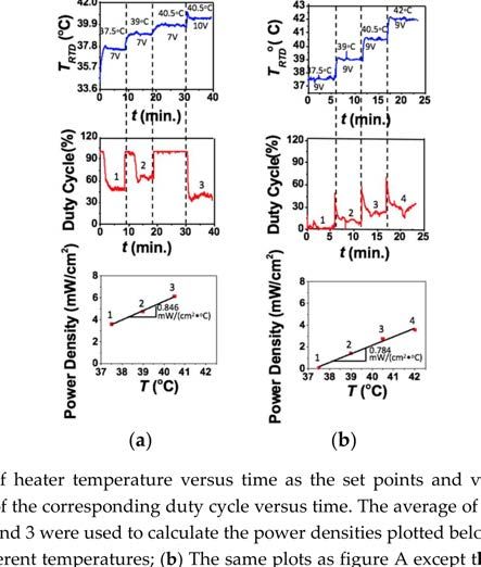
Micromachines 2018, 9, 170                                                                                   7 of 14

      Figure 4. (a) COMSOL thermal simulation results (left: top view; right: 3D view); (b) Lateral heat
      distribution of heater. Blue, red and green lines on simulation image (left) mark the horizontal line
      across which temperature was collected for their respective red, blue and green plots; (c) Vertical heat
      distribution of skin from the black line on simulation image (right).

     After calibrating the RTD and characterizing the RHE, we were able to establish a real time
PID feedback control as illustrated by the diagram in Figure 5a. The purpose of this system was to
demonstrate the functionality of the tattoo-like heater itself and was thus built with wires connecting
the heater to a data acquisition (DAQ) unit and a PC. The system can be made to be wireless in the
future by integrating it with a microcontroller unit (MCU), a Bluetooth low energy (BLE) chip and
a rechargeable battery on a miniature printed circuit board (PCB). The DC power to the RHE was
routed through an Omron DC-DC relay (G3CN) which was controlled by a computer using an output
DAQ (NI USB-6009). The computer ran a LabVIEW program which controlled the temperature of the
RHE using pulse width modulation (PWM). The RTD was connected to the DMM of an NI Elvis II,
which measured the RTD’s resistance and sent the readings to the LabVIEW program in real time. The
LabVIEW program converted the resistance readings into temperature using the following equation:

                                                             ∆R
                                               T = T0 +           ,                                              (1)
                                                          0.002R0

where the initial resistance R0 was measured at the room temperature T0 and the coefficient 0.0020 ◦ C−1
was the TCR obtained from the calibration on human skin in Figure 3d. The PID program then used
the real-time temperature feedback, along with a desired temperature set point, to determine how to
control the relay and thereby the PWM of the RHE. This allowed the program to keep the heater at a
set temperature or to adjust to a new temperature when demanded.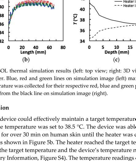
Micromachines 2018, 9, 170                                                                                     8 of 14

     Figure 5. (a) Circuit diagram of set up for operating heater with PID control. DMM measures resistance
     of RTD and feeds it into a computer with LabVIEW, The LabVIEW program calculates the temperature
     of the RTD using the RTD’s starting temperature, starting resistance and calibration constant. It then
     uses a PID algorithm to calculate the optimal duty cycle for PWM of the heater given the heater’s
     current temperature and the set point temperature for the heater. The LabVIEW program then uses
     the data acquisition unit (DAQ) to switch the relay on and off with the determined duty cycle, thus
     controlling how much total power is fed to the heater; (b) Temperature of the heater versus time
     measured with both the RTD and the IR camera as the heater is turned on at a set point of 38.5 ◦ C
     and then turned off. Heater is able to maintain set point temperature for an extended period of time;
     (c) Temperature of the heater versus time measured with both the RTD and the IR camera as the set
     point of the heater is changed while the voltage remains constant. At 40 ◦ C, 6.2 V is not sufficient for
     the heater to reach the set point, so the voltage is increased to 7 V, at which point the heater is able to
     reach and maintain a temperature of 40 ◦ C.

3. Results and Discussion
     First, to test if the device could effectively maintain a target temperature the DC voltage supply
was set to 6.2 V and the temperature was set to 38.5 ◦ C. The device was able to maintain a constant
temperature of 38.5 ◦ C for over 30 min on human skin until the heater was completely turned off to
finish the experiment as shown in Figure 5b. The heater reached the target temperature within 3 min
and the error between the target temperature and the device’s temperature never reached more than a
degree (Supplementary Information, Figure S4). The temperature readings of the RTD (black curve)
was also verified by the IR camera results (red curve).
     To test if the device could self-adjust when set temperature changes, we conducted an experiment
with multiple set temperatures (37 ◦ C, 38.5 ◦ C, 40 ◦ C) while the voltage supply was kept constant at
6.2 V (Figure 5c). For the first two temperatures (Stages I and II), the device was able to reach the set
temperatures and to maintain them at a steady state. In switching between these temperatures, no
changes were made except changing set point in the LabVIEW program. When the voltage was kept at
6.2 V and the target temperature was set to 40 ◦ C, which is marked as Stage III, the actual skin surface
temperature was not able to reach 40 ◦ C. It could only reach up to 39 ◦ C. This indicates insufficient
power supply even when the duty cycle of the PWM reached 100%. Therefore, the maximum steady
state temperature a heater can reach at 6.2 V with this set-up and under these circumstances is 39 ◦ C,
demonstrating a temperature to voltage ratio of 6.19 V/◦ C. This is lower than what was observed
when the power was applied directly to the RHE and not routed through the relay. This indicates that
Micromachines 2018, 9, 170                                                                           9 of 14

some power may be lost as the electricity passes through the relay and the wires thereto. We therefore
increased the voltage to 7 V and the skin surface was then successfully heated to 40 ◦ C, as in Stage IV.
Again, the temperature measured by the RTD (black) and the IR camera (red) are well matched. This
experiment demonstrates that when given a sufficient voltage supply, the stretchable tattoo-like heater
can automatically reach, maintain and change between desired temperatures without any manual
adjustment of the voltage.
     Due to the negligible stiffness of serpentine ribbons [48,49], the mechanical stiffness of our
tattoo-like heater is dominated by the supporting Tegaderm tape, whose Young’s modulus was
measured to be 7 MPa [42]. The effects of strain and skin deformation on our stretchable heater are
discussed in Supplementary Information, Figures S5 and S6. Figure S5 indicates that our RTD can
survive more than 70% tensile strain but its resistance is unfortunately slightly sensitive to strain. Due
to such strain effects, Figure S6 indicates that the RTD temperature is not accurate when the hand
closes but its measurement can recover when the hand restores its original configuration. With the PID
control, the RHE may under heat the skin due to the falsely perceived increase of RTD temperature
during hand closure, which will not cause any skin burn.
     To evaluate the power consumption of the tattoo-like heater, the duty cycles at different set
temperatures were investigated. The device was placed on a human palm with PID control. The
top frame in Figure 6a plots the actual skin temperature measured by the RTD versus time and the
labels are again voltage supply and set temperature. Some small overshooting of the temperature
occasionally happens at the points where voltage is changed but they are small and quickly rectified
by the controller. The device is not expected to undergo step changes in voltages during real life
application but these experiments show that the controller can react appropriately to those step changes
should they occur. At each set temperature, the steady state duty cycle was recorded. The middle
frame of Figure 6a shows the duty cycle versus time plot. The numbers mark the plateaus where the
device was considered to have reached steady state. The duty cycle for each set temperature was
calculated as the average of the duty cycle readings at these plateaus. The following equation was then
used for power calculation:
                                                   D      V2
                                            P=         ×     ,                                          (2)
                                                 100%      R
where D is the duty cycle, V is the voltage supplied to the RHE and R is the resistance of the RHE.
    If we define power density to be the power delivered to the skin per unit area of the RHE, power
density can be calculated through:

                                         Power Density = P/A,                                           (3)

where A represents the total area of the heater, which is 38.7 cm2 for our RHE. Plotting power density
versus the corresponding temperature as red markers in the bottom frame of Figure 6a, a linear relation
can be fitted. The slope of this linear curve is defined as the specific power flow (SPF), which represents
power density normalized to the applied thermal driving potential, that is, temperature difference.
The SPF of our stretchable tattoo-like heater is estimated to be 0.846 mW/(cm2 ·◦ C), which means that
to heat up a 1 cm2 area of this specific human palm by 1 ◦ C would consume a power of 0.846 mW.
     Considering convection and radiation between the heater and the ambient environment, it is
inaccurate to assume that all the heat generated by the RHE completely goes into the skin. To obtain a
more accurate estimation of the specific power flow into the skin, the entire experiment of Figure 6a
was repeated in Figure 6b but with insulation over the heater. A 4 cm thick layer of foam, which is a
well-known heat insulator, was taken from a delivery package and applied over the heater on the palm
to minimize heat loss into the environment. With this heat insulating foam, the SPF was found to be
0.784 mW/(cm2 ·◦ C) as given in Figure 6b bottom frame, which is 7.33% lower compared with that of
the exposed heater (0.846 mW/(cm2 ·◦ C)). This result indicates that about 7.33% of the heat generated
by the RHE was lost to the environment when the RHE was exposed to air.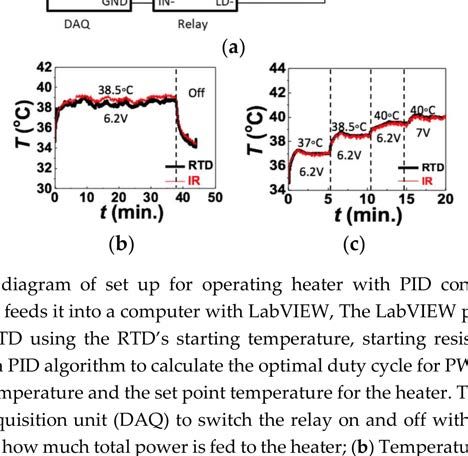
Micromachines 2018, 9, 170                                                                               10 of 14

     To compare our stretchable tattoo-like heater with other stretchable heaters in the literature, we
summarized their materials, substrates, power densities and SPFs in Table 1. In cases where power
supplied without using PWM, the value of D in Equation (2) was set to 100%. It is evident that the
SPF of our tattoo-like heater is the lowest among the stretchable heaters directly applied on human
skin, which is an active heat sink in comparison with air, polydimethylsiloxane (PDMS) and glass.
Moreover, our device is one of the first to implement real time feedback control for stretchable heaters
on human skin.
     If adopted for commercialization, our device could very feasibly be converted into a wireless
portable device with a battery-operated microcontroller as has been demonstrated for other joule
heating devices reported in the Table 1 [5,30,31].

     Figure 6. (a) Plot of heater temperature versus time as the set points and voltages are changed,
     followed by a plot of the corresponding duty cycle versus time. The average of the steady state duty
     cycles marked 1, 2 and 3 were used to calculate the power densities plotted below marked 1, 2 and 3,
     respectively, at different temperatures; (b) The same plots as figure A except the heater is insulated
     with a piece of foam.
Micromachines 2018, 9, 170 11 of 14
Table 1. Compiled information about different stretchable heaters.
T Sensor Feedback Target T Area Power Density SPF
Ref. Resistive Heating Element Substrate V (V) R (Ω) P (W)
on Site Control (◦ C) (cm2 ) (mW/cm2 ) mW/(cm2 ·◦ C)
Our
Yes Yes 43 Al (9 µm) Skin 10 17.2 38.7 2.38 61.44 0.78
device
[5] No No 43 Ag NW/SBS (18/82) Skin 3.7 ~2 91 ~7 ~80 0.9
[9] Yes Yes 40 Au (190 nm) Pig Skin 12 95.9 652 >40 *
[15] Yes No ∆T = 6 Au Skin – – 0.64 0.01 20.31 3
[30] Yes Yes 250 Ag/Ethylene Glycol (50 wt %) 50 µm PI 4.5 0.75 – 27 650 3
[31] No No 40 CuZr nanotrough network Skin 1.7 3.9 1.24 0.74 600 35
[39] No No 39 Ag NW /PDMS 132 mg m−2 Air 4 50 38.5 0.32 8.31 0.6
[39] No No 56 Ag NW /PDMS 396 mg m−2 Air 5 15 38.5 1.67 43.29 1
[41] Yes No 37 Cr/Au 7/70 nm PDMS 4.4 550 9 0.04 3.91 0.8
[40] Yes Yes 31 PE Yarn with CuNW coating Skin 1.4 1.66 30.16 1.18 39.12 5
* Assuming power for glass experiments was same as power for pig skin experiments.Micromachines 2018, 9, 170 12 of 14
4. Conclusions
A low cost, low power consumption stretchable tattoo-like heater was fabricated to reliably warm
the skin surface to a target temperature. The device combines a stretchable RHE and a stretchable
RTD into a single unit through the cost and time effective “cut-and-paste” fabrication method. The
device is thin (60 µm thick) and soft (7.4 MPa modulus) so that it can conform to the complex 3-D
surface of palms and can deform and remain attached during hand flexure without perceivable
mechanical resistance. The RHE is able to reach set temperatures with relatively even distribution,
including during hand movement. The RTD can monitor the real-time temperature of the palm
accurately, as verified by simultaneous IR measurements. Through PID temperature feedback control,
the device is able to maintain set temperatures for extended periods of time and can automatically
adjust to a different temperature if the set point is changed on the controller. The SPF of our device
is comparable with reported stretchable skin-mounted heaters. Its simple circuit and program can
easily be downscaled to a battery powered printed circuit board (PCB) and microcontroller, giving it
potential for point-of-care applications.
Supplementary Materials: The following are available online at http://www.mdpi.com/2072-666X/9/4/170/s1,
Figure S1: Snap button connections, Figure S2: RTD calibrated on hotplate, Figure S3: RTD calibrated on glass
with RHE, Figure S4: Error from set point during extended palm heating with device with PID control. Figure S5:
Stretchability test, Figure S6: Effect of skin deformation, Table S1: Steady state temperatures for different voltages
and temperature to voltage ratios, Video S1: Hand Clench Test.
Acknowledgments: This work is supported by the Office of Naval Research Young Investigator Award under
Contract N00014-16-1-2044 to N.L. and National Science Foundation Grant BET1250659 to K.R.D.
Author Contributions: A.S., E.H., S.Y. and N.L. conducted device design, fabrication, calibration and testing.
A.M. constructed the initial PID control algorithm and A.S. later revised it for this project. S.Q. performed the
COMSOL finite element modeling. N.L. and K.R.D. supervised and coordinated the project. A.S., N.L., S.Q. and
K.R.D. wrote the paper.
Conflicts of Interest: The authors declare no conflict of interest.
References
1. Petrofsky, J.; Berk, L.; Bains, G.; Khowailed, I.A.; Hui, T.; Granado, M.; Laymon, M.; Lee, H. Moist heat or
dry heat for delayed onset muscle soreness. J. Clin. Med. Res. 2013, 5, 416–425. [CrossRef] [PubMed]
2. Nadler, S.F.; Weingand, K.; Kruse, R.J. The physiologic basis and clinical applications of cryotherapy and
thermotherapy for the pain practitioner. Pain Physician 2004, 7, 395–399. [PubMed]
3. Brosseau, L.; Yonge, K.; Welch, V.; Marchand, S.; Judd, M.; Wells, G.; Tugwell, P. Thermotherapy for treatment
of osteoarthritis. Cochrane Database Syst. Rev. 2003, 4. [CrossRef]
4. Lehmann, J. Therapeutic Heat and Cold, 4th ed.; Williams & Wilkins: Baltimore, MD, USA, 1990.
5. Choi, S.; Park, J.; Hyun, W.; Kim, J.; Kim, J.; Lee, Y.B.; Song, C.; Hwang, H.J.; Kim, J.H.; Hyeon, T.;
et al. Stretchable heater using ligand-exchanged silver nanowire nanocomposite for wearable articular
thermotherapy. ACS Nano 2015, 9, 6626–6633. [CrossRef] [PubMed]
6. Sessler, D.I.; Rubinstein, E.H.; Moayeri, A. Physiologic responses to mild perianesthetic hypothermia in
humans. Anesthesiology 1991, 75, 594–610. [CrossRef] [PubMed]
7. Diller, K.R. Heat transfer in health and healing. J. Heat Transf. 2015, 137, 1030011–10300112. [CrossRef]
[PubMed]
8. Grahn, D.; Brock-Utne, J.G.; Watenpaugh, D.E.; Heller, H.C. Recovery from mild hypothermia can be
accelerated by mechanically distending blood vessels in the hand. J. Appl. Physiol. 1998, 85, 1643–1648.
[CrossRef] [PubMed]
9. Son, D.; Lee, J.; Qiao, S.; Ghaffari, R.; Kim, J.; Lee, J.E.; Song, C.; Kim, S.J.; Lee, D.J.; Jun, S.W.; et al.
Multifunctional wearable devices for diagnosis and therapy of movement disorders. Nat. Nanotechnol. 2014,
9, 397–404. [CrossRef] [PubMed]
10. Bagherifard, S.; Tamayol, A.; Mostafalu, P.; Akbari, M.; Comotto, M.; Annabi, N.; Ghaderi, M.; Sonkusale, S.;
Dokmeci, M.R.; Khademhosseini, A. Dermal patch with integrated flexible heater for on demand drug
delivery. Adv. Healthc. Mater. 2016, 5, 175–184. [CrossRef] [PubMed]Micromachines 2018, 9, 170 13 of 14
11. Petrofsky, J.S.; Laymon, M.; Lee, H. Effect of heat and cold on tendon flexibility and force to flex the human
knee. Med. Sci. Monit. Int. Med. J. Exp. Clin. Res. 2013, 19, 661–667. [CrossRef]
12. Michlovitz, S.; Hun, L.; Erasala, G.N.; Hengehold, D.A.; Weingand, K.W. Continuous low-level heat wrap
therapy is effective for treating wrist pain. Arch. Phys. Med. Rehabil. 2004, 85, 1409–1416. [CrossRef]
[PubMed]
13. Wang, S.; Li, M.; Wu, J.; Kim, D.-H.; Lu, N.; Su, Y.; Kang, Z.; Huang, Y.; Rogers, J.A. Mechanics of epidermal
electronics. J. Appl. Mech. 2012, 79, 031022. [CrossRef]
14. Wang, L.; Lu, N. Conformability of a thin elastic membrane laminated on a soft substrate with slightly wavy
surface. J. Appl. Mech. 2016, 83, 041007. [CrossRef]
15. Webb, R.C.; Bonifas, A.P.; Behnaz, A.; Zhang, Y.; Yu, K.J.; Cheng, H.; Shi, M.; Bian, Z.; Liu, Z.; Kim, Y.-S.; et al.
Ultrathin conformal devices for precise and continuous thermal characterization of human skin. Nat. Mater.
2013, 12, 938–944. [CrossRef] [PubMed]
16. Cartmell, J.V.; DeRosa, J.F. Capacitively Coupled Indifferent Electrode. U.S. Patent 4,669,468, 2 June 1987.
17. Roselli, R.J.; Diller, K.R. Biotransport: Principles and Applications, 2011 ed.; Springer: New York, NY, USA, 2011;
ISBN 978-1-4419-8118-9.
18. Tuckey, J. Forced-air warming blanket and surgical access. Anaesthesia 1999, 54, 97–98. [CrossRef] [PubMed]
19. Kimberger, O.; Held, C.; Stadelmann, K.; Mayer, N.; Hunkeler, C.; Sessler, D.I.; Kurz, A. Resistive polymer
versus forced-air warming: Comparable heat transfer and core rewarming rates in volunteers. Anesth. Analg.
2008, 107, 1621–1626. [CrossRef] [PubMed]
20. Rogers, J.A.; Someya, T.; Huang, Y. Materials and mechanics for stretchable electronics. Science 2010, 327,
1603–1607. [CrossRef] [PubMed]
21. Kim, D.-H.; Ghaffari, R.; Lu, N.; Rogers, J.A. Flexible and stretchable electronics for biointegrated devices.
Annu. Rev. Biomed. Eng. 2012, 14, 113–128. [CrossRef] [PubMed]
22. Suo, Z. Mechanics of stretchable electronics and soft machines. MRS Bull. 2012, 37, 218–225. [CrossRef]
23. Nassar, J.M.; Rojas, J.P.; Hussain, A.M.; Hussain, M.M. From stretchable to reconfigurable inorganic
electronics. Extreme Mech. Lett. 2016, 9, 245–268. [CrossRef]
24. Sekitani, T.; Noguchi, Y.; Hata, K.; Fukushima, T.; Aida, T.; Someya, T. A rubberlike stretchable active matrix
using elastic conductors. Science 2008, 321, 1468–1472. [CrossRef] [PubMed]
25. Jung, S.; Kim, J.H.; Kim, J.; Choi, S.; Lee, J.; Park, I.; Hyeon, T.; Kim, D.-H. Reverse-micelle-induced
porous pressure-sensitive rubber for wearable human–machine interfaces. Adv. Mater. 2014, 26, 4825–4830.
[CrossRef] [PubMed]
26. Kim, Y.; Zhu, J.; Yeom, B.; Di Prima, M.; Su, X.; Kim, J.-G.; Yoo, S.J.; Uher, C.; Kotov, N.A. Stretchable
nanoparticle conductors with self-organized conductive pathways. Nature 2013, 500, 59–63. [CrossRef]
[PubMed]
27. Chun, K.-Y.; Oh, Y.; Rho, J.; Ahn, J.-H.; Kim, Y.-J.; Choi, H.R.; Baik, S. Highly conductive, printable and
stretchable composite films of carbon nanotubes and silver. Nat. Nanotechnol. 2010, 5, 853–857. [CrossRef]
[PubMed]
28. Ma, R.; Lee, J.; Choi, D.; Moon, H.; Baik, S. Knitted fabrics made from highly conductive stretchable fibers.
Nano Lett. 2014, 14, 1944–1951. [CrossRef] [PubMed]
29. Park, M.; Im, J.; Shin, M.; Min, Y.; Park, J.; Cho, H.; Park, S.; Shim, M.-B.; Jeon, S.; Chung, D.-Y.; et al.
Highly stretchable electric circuits from a composite material of silver nanoparticles and elastomeric fibres.
Nat. Nanotechnol. 2012, 7, 803–809. [CrossRef] [PubMed]
30. Jang, J.; Hyun, B.G.; Ji, S.; Cho, E.; An, B.W.; Cheong, W.H.; Park, J.-U. Rapid production of large-area,
transparent and stretchable electrodes using metal nanofibers as wirelessly operated wearable heaters.
NPG Asia Mater. 2017, 9, e432. [CrossRef]
31. An, B.W.; Gwak, E.-J.; Kim, K.; Kim, Y.-C.; Jang, J.; Kim, J.-Y.; Park, J.-U. Stretchable, transparent electrodes
as wearable heaters using nanotrough networks of metallic glasses with superior mechanical properties and
thermal stability. Nano Lett. 2016, 16, 471–478. [CrossRef] [PubMed]
32. Moon, G.D.; Lim, G.-H.; Song, J.H.; Shin, M.; Yu, T.; Lim, B.; Jeong, U. Highly stretchable patterned gold
electrodes made of Au nanosheets. Adv. Mater. 2013, 25, 2707–2712. [CrossRef] [PubMed]
33. Gray, D.S.; Tien, J.; Chen, C.S. High-conductivity elastomeric electronics. Adv. Mater. 2004, 16, 393–397.
[CrossRef]Micromachines 2018, 9, 170 14 of 14
34. Li, T.; Suo, Z.; Lacour, S.P.; Wagner, S. Compliant thin film patterns of stiff materials as platforms for
stretchable electronics. J. Mater. Res. 2005, 20, 3274–3277. [CrossRef]
35. Xu, S.; Zhang, Y.; Cho, J.; Lee, J.; Huang, X.; Jia, L.; Fan, J.A.; Su, Y.; Su, J.; Zhang, H.; et al. Stretchable batteries
with self-similar serpentine interconnects and integrated wireless recharging systems. Nat. Commun. 2013,
4, 1543. [CrossRef] [PubMed]
36. Fan, J.A.; Yeo, W.-H.; Su, Y.; Hattori, Y.; Lee, W.; Jung, S.-Y.; Zhang, Y.; Liu, Z.; Cheng, H.; Falgout, L.; et al.
Fractal design concepts for stretchable electronics. Nat. Commun. 2014, 5, 3266. [CrossRef] [PubMed]
37. Yang, S.; Ng, E.; Lu, N. Indium Tin Oxide (ITO) serpentine ribbons on soft substrates stretched beyond 100%.
Extreme Mech. Lett. 2015, 2, 37–45. [CrossRef]
38. Kim, D.-H.; Lu, N.; Ma, R.; Kim, Y.-S.; Kim, R.-H.; Wang, S.; Wu, J.; Won, S.M.; Tao, H.; Islam, A.; et al.
Epidermal electronics. Science 2011, 333, 838–843. [CrossRef] [PubMed]
39. Hong, S.; Lee, H.; Lee, J.; Kwon, J.; Han, S.; Suh, Y.D.; Cho, H.; Shin, J.; Yeo, J.; Ko, S.H. Highly stretchable
and transparent metal nanowire heater for wearable electronics applications. Adv. Mater. 2015, 27, 4744–4751.
[CrossRef] [PubMed]
40. Cheng, Y.; Zhang, H.; Wang, R.; Wang, X.; Zhai, H.; Wang, T.; Jin, Q.; Sun, J. Highly stretchable and conductive
copper nanowire based fibers with hierarchical structure for wearable heaters. ACS Appl. Mater. Interfaces
2016, 8, 32925–32933. [CrossRef] [PubMed]
41. Kim, J.; Lee, M.; Shim, H.J.; Ghaffari, R.; Cho, H.R.; Son, D.; Jung, Y.H.; Soh, M.; Choi, C.; Jung, S.; et al.
Stretchable silicon nanoribbon electronics for skin prosthesis. Nat. Commun. 2014, 5, 5747. [CrossRef]
[PubMed]
42. Yang, S.; Chen, Y.-C.; Nicolini, L.; Pasupathy, P.; Sacks, J.; Su, B.; Yang, R.; Sanchez, D.; Chang, Y.-F.;
Wang, P.; et al. “Cut-and-Paste” Manufacture of multiparametric epidermal sensor systems. Adv. Mater.
2015, 27, 6423–6430. [CrossRef] [PubMed]
43. Lu, N.; Wang, X.; Suo, Z.; Vlassak, J. Metal films on polymer substrates stretched beyond 50%. Appl. Phys. Lett.
2007, 91, 221909. [CrossRef]
44. Lu, N.; Kim, D.-H. Flexible and stretchable electronics paving the way for soft robotics. Soft Robot. 2013, 1,
53–62. [CrossRef]
45. Kim, J.; Banks, A.; Cheng, H.; Xie, Z.; Xu, S.; Jang, K.I.; Lee, J.W.; Liu, Z.; Gutruf, P.; Huang, X.; et al.
Epidermal electronics with advanced capabilities in near-field communication. Small 2015, 11, 906–912.
[CrossRef] [PubMed]
46. Methods of Increasing Emissivity in the Infrared Spectrum. Available online: http://www.optotherm.com/
emiss-increasing.htm (accessed on 2 May 2016).
47. Cetingül, M.P.; Herman, C. A heat transfer model of skin tissue for the detection of lesions: Sensitivity
analysis. Phys. Med. Biol. 2010, 55, 5933–5951. [CrossRef] [PubMed]
48. Widlund, T.; Yang, S.; Hsu, Y.-Y.; Lu, N. Stretchability and compliance of freestanding serpentine-shaped
ribbons. Int. J. Solids Struct. 2014, 51, 4026–4037. [CrossRef]
49. Yang, S.; Qiao, S.; Lu, N. Elasticity solutions to nonbuckling serpentine ribbons. J. Appl. Mech. 2017,
84, 021004. [CrossRef]
© 2018 by the authors. Licensee MDPI, Basel, Switzerland. This article is an open access
article distributed under the terms and conditions of the Creative Commons Attribution
(CC BY) license (http://creativecommons.org/licenses/by/4.0/).You can also read