ETT 0833 Multi-Touch Operating Panel - SIGMATEK
←
→
Page content transcription
If your browser does not render page correctly, please read the page content below
ETT 0833
     Multi-Touch Operating Panel

Date of creation: 13.08.2015   Version date: 02.03.2021   Article number: 01-230-0833-E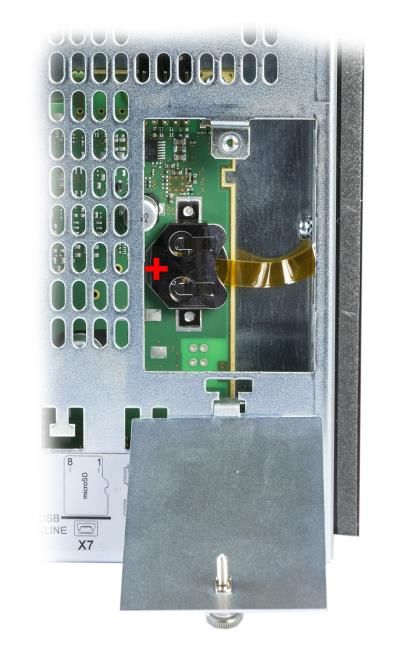
Publisher: SIGMATEK GmbH & Co KG
                                   A-5112 Lamprechtshausen
                                      Tel.: +43/6274/4321
                                    Fax: +43/6274/4321-18
                                   Email: office@sigmatek.at
                               WWW.SIGMATEK-AUTOMATION.COM

                                               Copyright © 2015
                                            SIGMATEK GmbH & Co KG

                                      Translation from German

All rights reserved. No part of this work may be reproduced, edited using an electronic system, duplicated or dis-
tributed in any form (print, photocopy, microfilm or in any other process) without the express permission.

We reserve the right to make changes in the content without notice. The SIGMATEK GmbH & Co KG is not responsi-
ble for technical or printing errors in the handbook and assumes no responsibility for damages that occur through
use of this handbook.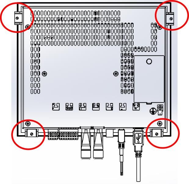
MULTI-TOUCH OPERATING PANEL                    ETT 0833

Multi-Touch Operating Panel                                                 ETT 0833

The Multi-Touch Operating Panel is an intelligent panel for visualizing, operating and moni-
toring automated processes.

A capacitive touch screen serves as the input medium for process data and parameters.
The output is shown on an 8.4" SVGA TFT color display.

With the LSE mask editor, graphics can be created on the PC, then stored and displayed
on the Multi-Touch Operating Panel.

The available interfaces can be used to exchange process data or configure the multi-touch
terminal. A microSD card serves as the storage medium for the operating system, applica-
tion and application data.

02.03.2021                                                                          Page 1
ETT 0833              MULTI-TOUCH OPERATING PANEL

Contents
1    Technical Data ........................................................................ 4
     1.1         Performance Data ......................................................................... 4

     1.2         Electrical Requirements ............................................................... 5

     1.3         Terminal ......................................................................................... 5

     1.4         Environmental Conditions ........................................................... 5

     1.5         8.4" SVGA Display ........................................................................ 6

     1.6         Control Unit ................................................................................... 6

     1.7         Digital Outputs .............................................................................. 8

     1.8         Digital Inputs ................................................................................. 8

     1.9         Miscellaneous ............................................................................... 9

2    Mechanical Dimensions ........................................................10
     2.1         Up to HW Version 2.30 ............................................................... 10

     2.2         Starting from HW Version 2.40 .................................................. 11

3    Connector Layout ..................................................................12
     3.1         Applicable Connectors ............................................................... 16

4    Buffer Battery .........................................................................17
     4.1         Exchanging the Battery .............................................................. 18

5    Cooling ...................................................................................19

6    Mounting Instructions ...........................................................19

Page 2                                                                                               02.03.2021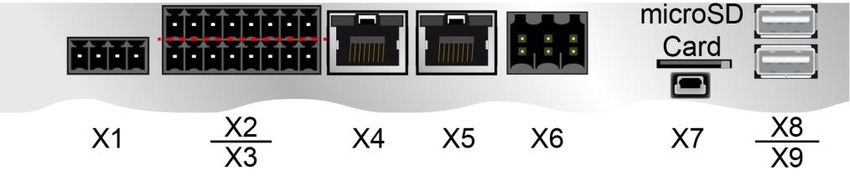
MULTI-TOUCH OPERATING PANEL                                   ETT 0833

7    Wiring Guidelines .................................................................. 22
      7.1        Ground ......................................................................................... 22

      7.2        Shielding ...................................................................................... 22

      7.3        ESD Protection ............................................................................ 22

      7.4        USB Interface Connections ....................................................... 22

8    CAN Bus Setup ...................................................................... 23
      8.1        CAN Bus Station Number .......................................................... 23

      8.2        Number of CAN Bus Participants .............................................. 23

      8.3        CAN Bus Data Transfer Rate ..................................................... 23

9    CAN Bus Termination ........................................................... 24

10   Process Diagram ................................................................... 25

11   Status and Error Messages .................................................. 26

12   Logo Backlighting (optional) ................................................ 34

13   Display „Burn-In“ Effect ....................................................... 34

14   Cleaning the Touch Screen .................................................. 35

15   Disposal ................................................................................. 36

02.03.2021                                                                                               Page 3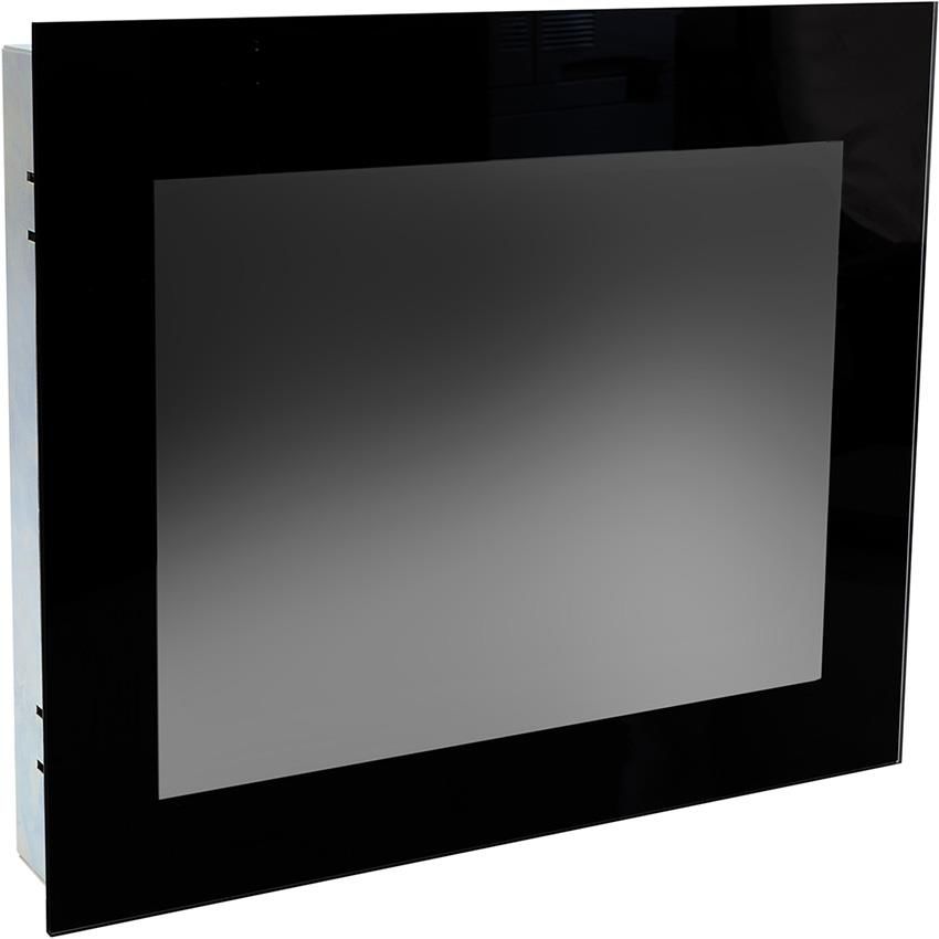
ETT 0833                        MULTI-TOUCH OPERATING PANEL

1         Technical Data
1.1         Performance Data

      Processor                                                     EDGE2 Technology

      Processor cores                                                        21)

      Internal cache                                           32-kbyte L1 Instruction Cache

                                                                  32-kbyte L1 Data Cache

                                                                    512-kbyte L2 Cache

      Internal program and data                                          512-Mbyte
      memory (DDR3 RAM)

      Internal remnant data memory                           512-kbyte SRAM (battery buffered)

      Internal storage device                                       512-Mbyte microSD

      Internal I/O                                                           yes

      Interfaces                                                     2x USB 2.0 Type A

                                                           1x USB-OTG (host/device), type Mini B

                                                                         2x Ethernet

                                                          1x CAN bus (not galvanically separated)

      Internal interface connections and                            1x TFT color display
      devices
                                                                 1x USB (touch connection)

      Display                                                      8.4" TFT color display

      Resolution                                                       800 x 600 Pixel

      Control panel                                         Touch screen (projective capacitive)

      Signal generator                                                       no

      Status LEDs                                                            no

      Logo backlighting                                                if existing: RGB

      Real-time clock                                               yes (battery buffered)

      Cooling                                                         passive (fanless)

1)
     Attention: When programming (with LASAL) on multicore CPUs, particular focus must be placed on thread security!

Page 4                                                                                                02.03.2021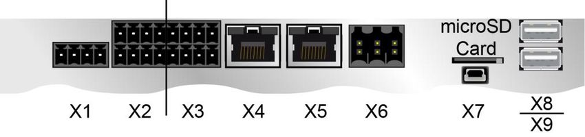
MULTI-TOUCH OPERATING PANEL ETT 0833
1.2 Electrical Requirements
Supply voltage typically +24 V DC (+18-30 V DC)
Current consumption of power typically 350 mA maximum 560 mA
supply at +24 V (without externally connected (with externally connected devices)
devices)
Inrush current maximum 2 A for 10 s
1)
UL standard for UL : must be supplied with SELV / PELV and Limited Energy
Digital output also is SELV / Limited Energy.
1)
In US according to Class 2 UL 1310 or UL 61010-1, 3rd edition, chapter 9.4 or LPS (limited power supply)
UL 60950-1 or Limited Energy UL 1585
1.3 Terminal
Dimensions 230.4 x 200.3 x 45.9 mm (W x H x D)
Material front plate: 4 mm glass on 1 mm aluminium frame
Weight typically 1.8 kg
Due to the glass surface, caution must be taken to ensure that it is not damaged
during mounting via strong impacts on the edges or corners!
1.4 Environmental Conditions
Storage temperature -10 ... +75 °C
Environmental temperature 0 ... +55 °C
Humidity 10-95 %, non-condensing
Operating conditions Pollution degree 2
indoor use
altitude up to 2000 m
EMC resistance in accordance with EN 61000-6-2 (industrial area)
EMC - noise generation in accordance with EN 61000-6-4 (industrial area)
Vibration resistance EN 60068-2-6 2-9 Hz: amplitude 3.5 mm
9-200 Hz: 1 g (10 m/s²)
Shock resistance EN 60068-2-27 15 g (150 m/s²)
duration 11 ms, 18 shocks
Protection type EN 60529 front: IP65 (no UL-rating)
protected through the housing cover: IP20 (no UL-rating)
02.03.2021 Page 5
ETT 0833                      MULTI-TOUCH OPERATING PANEL

1.5        8.4" SVGA Display

  Type                                                                8.4" TFT color display

  Resolution                                                         SVGA 800 x 600 Pixel

  Color depth                                                                 24 Bit RGB

  LCD mode                                                               normally white1)

  LCD Polarizer                                                           transmissive2)

  Pixel size                                                            0.213 x 0.213 mm

  Active surface                                                      170.40 x 127.80 mm

  Backlighting                                                                    LED

  Contrast                                                                    typically 450

  Brightness                                                           typically 330 cd/m²

  Angle CR ≥ 10                                             left and right 65°, above 60° , below 55°

  Lifespan                              by compliance with the ambient conditions, the brightness of the display sinks
                                              after 50,000 operating hours to 50 % of the original brightness

 1)
      If there is no display data, the display is white (LED backlight on).
 2)
      Display technology, with which display backlighting is used.

      Due to the production process of displays defective pixels cannot be excluded
                                       completely.

1.6        Control Unit

  Touch panel                                                   projective capacitive touch panel

  Surface                                                      4 mm front glass with black frame

  Cleaning                                                  see chapter: Cleaning the Touch Screen

      The ETT 0833 has a projective capacitive touch screen built in, with which
 10-finger input, Zoom and gesture functions can be implemented. Data can be input
 using fingers, a projective capacitive touch pen and while wearing thin gloves. The
   device must always have a good ground connection so that the function of the
    touch screen is stable. In addition, it may be necessary to calibrate the touch
                  screen for the respective environmental conditions.

Page 6                                                                                                    02.03.2021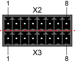
MULTI-TOUCH OPERATING PANEL ETT 0833
L'ETT 0833 dispose d’un écran tactile capacitif projectif avec lequel de gestes avec
10 doigts, multi gestes et fonctions zoom peuvent être réalisées. Les données peu-
vent être saisies en utilisant les doigts, y compris en portant des gants minces, ou
bien un stylo tactile capacitif projectif. Le dispositif doit toujours être correctement
mis à la terre afin d’assurer le fonctionnement stable de l'écran tactile. En outre, il
se pourrait que l'écran tactile doive être calibré pour les conditions environnemen-
tales respectives.
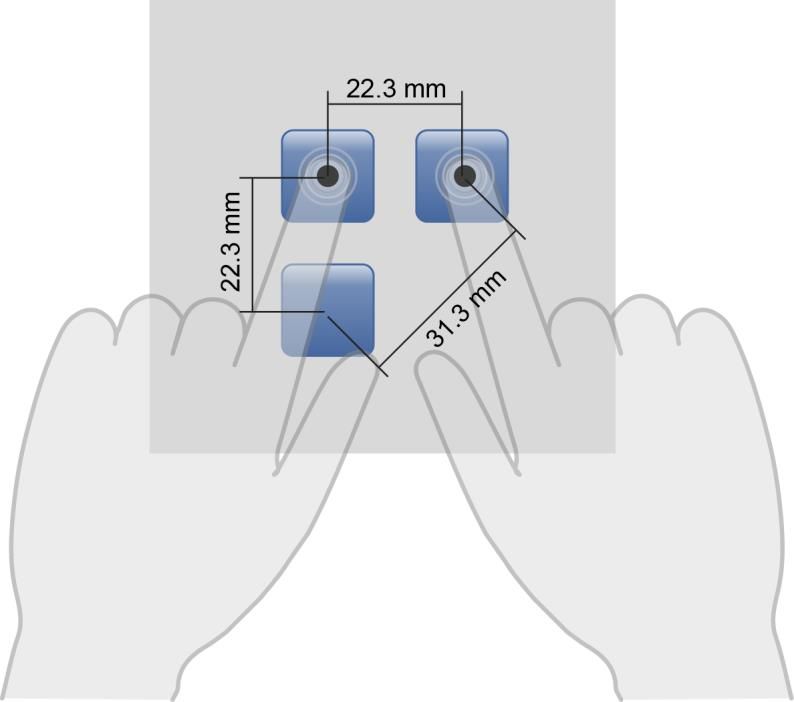
Required distance between operating elements for multi-touch applications:
In order to guarantee smooth operation in multi-touch applications, buttons and control
elements, which should be operated at the same time, must have the minimum distance
shown below (depending on the estimated touch point).
The size of the buttons and control elements directly affects the usability of the
application. So small control elements should be avoided.
02.03.2021 Page 7ETT 0833 MULTI-TOUCH OPERATING PANEL 1.7 Digital Outputs Number 8 Short-circuit proof yes Maximum permitted contin- 0,5 A uous load current / channel Maximum total current (all 2 A (100 % of on time) 8-channels) Voltage drop over power 1V supply (output active) Residual current 12 µA (off) Turn-on delay < 400 s Turn-off delay < 400 s Max. braking energy of 1 channel 0.12 [Joules] inductive loads 1.8 Digital Inputs Number 8 Input voltage typically +24 V maximum +30 V Signal level low: < +4.5 V high: > +14 V Switching threshold typically +11 V Input current typically 5 mA at + 24 V Input delay typically 5 ms Page 8 02.03.2021
MULTI-TOUCH OPERATING PANEL                                ETT 0833

1.9    Miscellaneous

  Article number                                          01-230-0833

  Hardware version                                             2.x

  Operating system                                        Salamander

  Standard IP address                                     10.10.150.1

  Standard                                              UL 61010-2-201

  Approbations                                            UL, cUL, CE

                        Warning to the installer

                        Temperature rating of the cable to be connected to the terminals

                        Temperature resistance of the cable insulation must be above 70 ° C

02.03.2021                                                                                     Page 9
ETT 0833 MULTI-TOUCH OPERATING PANEL 2 Mechanical Dimensions 2.1 Up to HW Version 2.30 Page 10 02.03.2021
MULTI-TOUCH OPERATING PANEL   ETT 0833

2.2   Starting from HW Version 2.40

02.03.2021                                                Page 11
ETT 0833           MULTI-TOUCH OPERATING PANEL

3   Connector Layout
Backside starting with HW 2.20

Backside up to HW 2.10

X1: Supply (4-pin Phoenix RM 3.5)

                                 Pin         Function
                                  1      +24 V DC DIG IOs
                                  2          +24 V DC
                                  3            GND
                                  4            GND

Page 12                                                     02.03.2021
MULTI-TOUCH OPERATING PANEL ETT 0833
X2 and X3: 8 Digital Outputs, 8 Digital Inputs (8-pin Phoenix RM 3.5)
Starting with HW 2.20
X2: Pin Assignment
Pin Function
1 Output 1
2 Output 2
3 Output 3
4 Output 4
5 Input 1
6 Input 2
7 Input 3
8 Input 4
X3: Pin Assignment
Pin Function
1 Output 5
2 Output 6
3 Output 7
4 Output 8
5 Input 5
6 Input 6
7 Input 7
8 Input 8
Up to HW 2.10
X2: Pin Assignment
Pin Function
1 Output 1
2 Output 2
3 Output 3
4 Output 4
5 Output 5
6 Output 6
7 Output 7
8 Output 8
X3: Pin Assignment
Pin Function
1 Input 1
2 Input 2
3 Input 3
4 Input 4
5 Input 5
6 Input 6
7 Input 7
8 Input 8
02.03.2021 Page 13ETT 0833 MULTI-TOUCH OPERATING PANEL
X4, X5: Ethernet 10/100 (RJ45)
Pin Function
1 Rx+
2 Rx-
3 Tx+
4 n.c.
5 n.c.
6 Tx-
7 n.c.
8 n.c.
n.c. = do not use
Problems can arise if a control is connected to an IP network, which contains mod-
ules that do not have a SIGMATEK operating system. With such devices, Ethernet
packets could be sent to the control with such a high frequency (i.e. broadcasts),
that the high interrupt load could cause a real-time runtime error or runtime error.
By configuring the packet filter (Firewall or Router) accordingly however, it is pos-
sible to connect a network with SIGMATEK hardware to a third party network with-
out triggering the error mentioned above.
Des problèmes peuvent survenir si un automate est connecté à un réseau IP con-
tenant des modules qui ne fonctionnent pas sous un système d'exploitation
SIGMATEK. Avec de tels dispositifs, les paquets Ethernet peuvent être envoyés à
l’automate avec une fréquence tellement élevée (càd. diffusion), que les interrup-
tions ainsi générées peuvent provoquer une erreur d'exécution. En configurant
d’une façon appropriée le filtre de paquets (pare-feu ou un routeur) il est toutefois
possible de connecter un réseau avec le matériel SIGMATEK à un réseau tiers sans
déclencher l'erreur mentionnée ci-dessus.
For use in local networks only, not in telecommunication circuits.
Pour une utilisation dans les réseaux locaux uniquement, et non pas dans de cir-
cuits de télécommunications.
Page 14 02.03.2021MULTI-TOUCH OPERATING PANEL ETT 0833
X6: CAN (6-pin Weidmüller RM 3.5 not galvanically separated)
Pin Function
1 CAN A (LOW)
2 CAN B (HIGH)
3 CAN A (LOW)
4 CAN B (HIGH)
5 GND
6 GND
X7: microSD Card
Pin Function
1 DAT2
2 CD/DAT3
3 CMD
4 +3V3
5 CLK
6 GND
7 DAT0
8 DAT1
It is recommended that only storage media provided by SIGMATEK
(CompactFlash cards, microSD cards etc.) be used.
Order number for 512 Mbyte EDGE2: 12-630-055
Il est recommandé de n’utiliser que les supports de stockage approuvés par
SIGMATEK (compact flash, microSD, etc.).
Numéro de commande pour la carte microSD 512 Mo EDGE2 est le: 12-630-055
The microSD card is not meant to be used as a removable media and thus only
should be removed from the card holder for maintenance purposes.
The number of read and write actions have a significant influence on the
lifespan of the storage media.
Le nombre de cycles de lecture et d'écriture a l’influence notable sur la durée de vie
des supports de stockage.
02.03.2021 Page 15ETT 0833 MULTI-TOUCH OPERATING PANEL
X7: USB 2.0 (Type Mini B) (can be used with OTG cable as USB host, otherwise USB
Device for service purposes)
Pin Function
1 +5 V
2 D-
3 D+
4 ID
5 GND
X8, X9: USB 2.0 (Type A)
Pin Function
1 +5 V_USB
2 D-
3 D+
4 GND
It should be noted that many of the USB devices on the market do not comply with
USB specifications; this can lead to device malfunctions. This can lead to malfunc-
tion of the device. It is also possible that these devices will not be detected at the
USB port or function correctly. Therefore, it is recommended that every USB stick
be tested before actual use.
Il faut souligner que la plupart des périphériques USB sur le marché ne sont pas
conformes aux spécifications USB, ce qui peut entraîner des dysfonctionnements
de l'appareil. Il est également possible que ces dispositifs ne seront pas détectés
par le port USB ou qu’ils ne fonctionnent pas correctement. Par conséquent, il est
recommandé que chaque clé USB soit testée avant l'utilisation sur l’automate.
3.1 Applicable Connectors
X1: 4-pin Phoenix plug with spring terminal FK-MCP 1.5/ 4-ST-3.5 (included with deliv-
ery)
X2: 2x 8-pin Phoenix plug with spring terminal FMC 1.5/ 8-ST-3.5 (included with deliv-
ery)
X4, X5: 8-pin RJ45
X6: 6-pin Weidmüller plug B2L3.5/6 (included in delivery)
X7: USB Type Mini B OTG cable (host) or USB Type Mini B to USB Type A cable
(device) (no included with delivery)
X8, X9: USB 4-pin, Type A (downstream connector) (no included with delivery)
Page 16 02.03.2021MULTI-TOUCH OPERATING PANEL ETT 0833
4 Buffer Battery
The exchangeable buffer battery ensures that the clock time (RTC) and zero voltage safe
data are preserved in the absence of a supply voltage. A lithium battery is installed at the
manufacturer.
The battery has enough capacity to preserve data in the absence of a supply voltage for up
to 5 years.
Battery order number: 01-690-055
COMPANY DATA
Lithium battery RENATA 3.0 V/235 mAh
Use batteries from RENATA with the label CR2032 only!
WARNING!
Incorrect use of the batteries could result in fire or explosion! Do not recharge, dis-
assemble or throw batteries into fire!
Utilisez seulement des piles de RENATA CR2032!
ATTENTION!
La pile peut exploser si elle n’est pas manipulée correctement! Ne pas recharger,
démonter ou jeter au feu!
When the battery voltage is in between the supervisor circuit thresholds it may happen that
the battery is detected "good" during operation but "low" after a power cycle. If this happens
it is recommended to replace the battery.
02.03.2021 Page 17ETT 0833 MULTI-TOUCH OPERATING PANEL
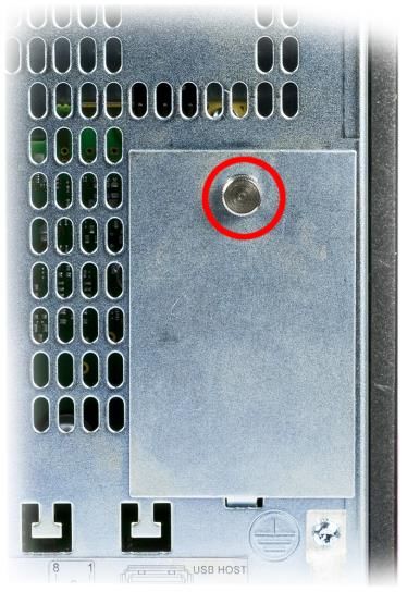
4.1 Exchanging the Battery
1. Switch off the ETT‘s power supply. From
this moment on you have three minutes to
exchange the battery.
2. Open the screws of the battery cover.
3. Take out the battery with the help of the
strap.
4. Insert new battery with the correct polarity
(+ pole at the back, see graphics).
5. Close battery cover.
Page 18 02.03.2021MULTI-TOUCH OPERATING PANEL ETT 0833
5 Cooling
The terminal's power loss can reach up to 13 Watts. To ensure the necessary air circulation
for cooling, the following mounting instructions must be followed!
6 Mounting Instructions
Due to the glass surface, caution must be taken to ensure that it is not damaged
during mounting via strong impacts on the edges or corners!
The following hints should be cares for when mounting the terminal:
- For mounting with the spring clips included in delivery a material thickness of the
wall between min. 1 mm and max. 6 mm is recommended. The spring clips may
be fixed with a maximum torque of 0.15-0.20 Nm. For this a slotted screwdriver
3x0.5 must be used.
- To avoid damages of the glass care for cleanliness (dirt, bumps) of the contact ar-
ea of the wall during mounting. Bumps can lead to tensions in the glass or intru-
sion of dust and water.
Required Cutout for Mounting the Terminal:
Control cabinet cutout width X 215 mm
Control cabinet cutout height Y 182.5 mm
Maximum thickness of control cabinet wall Z 6 mm
02.03.2021 Page 19ETT 0833 MULTI-TOUCH OPERATING PANEL - Only one screw terminal should be used per corner of the device. Page 20 02.03.2021
MULTI-TOUCH OPERATING PANEL                ETT 0833

The following distance from the housing should be maintained:

       - Left and right 5 cm
       - Back side, above and below 10 cm

Section side view:                                   Section top view

The specified mounting distances can be reduced under some circumstances, if appropriate
action and technical precautions are taken to drain the resulting loss.

A mounting position of 60°-120° is also required.

02.03.2021                                                                     Page 21
ETT 0833 MULTI-TOUCH OPERATING PANEL 7 Wiring Guidelines 7.1 Ground The device must be grounded to protective earth (PE) via the blade terminal provided. In addition, ensure that when installing into the control cabinet, a large grounding surface is provided. It is important to establish a low-Ohm connection to ground to ensure error-free function. The ground connection must be made with the maximum wire cross-section and largest (electrical) surface possible. The cable length of the ground connection must also be kept as short as possible. 7.2 Shielding For the Ethernet, CAT5 cables with shielded RJ45 connectors must be used. The shielding on the CAT5 cable is connected to ground via the RJ45 plug connector. Noise signals can therefore be prevented from reaching the electronics and affecting the function. 7.3 ESD Protection Typically, USB devices (keyboard, mouse) are not equipped with shielded cables. These devices are disrupted by ESD and in some instances, no longer function. Before any device is connected to, or disconnected from the terminal, the potential should be equalized (by touching the control cabinet or ground terminal). This will allow the dissipa- tion of electrostatic loads (caused by clothing/shoes). 7.4 USB Interface Connections The terminal has a USB interface. In LASAL, this interface can be used for various USB devices (keyboard, mouse, storage media, hubs, etc.). Using a hub, several USB devices can be connected that are then fully functional in LASAL. Page 22 02.03.2021
MULTI-TOUCH OPERATING PANEL ETT 0833
8 CAN Bus Setup
This section explains how to configure a CAN bus correctly. The following parameters must
first be set: Station number and data transfer rate.
8.1 CAN Bus Station Number
Each CAN bus station is assigned its own station number. With this station number, data
can be exchanged with other stations connected to the bus. In a CAN bus system however,
each station number can only be assigned once!
8.2 Number of CAN Bus Participants
The maximum number of participants on the CAN bus depends on the cable length, termi-
nation resistance, data transfer rate and the drivers used in the participants.
With a termination resistance of 2x 120 , at least 100 bust participants are possible.
8.3 CAN Bus Data Transfer Rate
Various data transfer rates (baud rates) can be set on the CAN bus. The longer the bus line
is, the lower the data transfer rate that must be selected.
Value Baud Rate Maximum Length
0 615 Kbits/s1) 60 m
1 500 kbit/s 80 m
2 250 Kbits/s 160 m
3 125 Kbits/s 320 m
4 100 Kbits/s 400 m
5 50 Kbits/s 800 m
6 20 kbits/s 1200 m
7 1 Mbit/s 30 m
1)
only between devices with EDGE2 technology
These values apply to the following cable: 120 Twisted Pair.
Note: For the CAN bus protocol: 1 kbit/s = 1 kBaud.
02.03.2021 Page 23ETT 0833 MULTI-TOUCH OPERATING PANEL
9 CAN Bus Termination
In a CAN bus system, both end modules must be terminated. This is necessary to avoid
transmission errors caused by reflections in the line.
For the CAN interfaces, the terminal has a 120 switchable termination resistor the can be
turned on and off through the application.
The termination is made by an internal switchable 120 resistor between CAN A
(LOW) and CAN B (HIGH).
Page 24 02.03.2021MULTI-TOUCH OPERATING PANEL ETT 0833 10 Process Diagram 02.03.2021 Page 25
ETT 0833             MULTI-TOUCH OPERATING PANEL

11 Status and Error Messages

Status and error messages are shown in the status test of the LASAL CLASS software.
POINTER or CHKSUM messages can also be shown on the terminal screen.

With missing microSD card or a microSD card with a defective operating system version the
terminal will not boot and the logo is not lighted!

Number     Message          Definition                                 Cause/Solution

   00      RUN RAM          The user program is currently running in   INFO
                            RAM.
                            The display is not affected.
   01      RUN ROM          The user program stored in the program     Info
                            memory module loaded into the RAM is
                            currently running.
                            The display is not affected.
   02      RUNTIME          The total time for all cyclic objects      Optimize the application's cyclic
                            exceeds the maximum time; the time         task.
                            can be configured using two system
                                                                       Use higher capacity CPU
                            variables:
                                                                       Configure preset value
                            -     - Runtime: Remaining time
                            -     SWRuntime: Preset value for
                                  runtime counter
   03      POINTER          Incorrect program pointers were detect-    Possible Causes:
                            ed before running the user program
                                                                       - The program memory module is
                                                                         missing, not programmed or de-
                                                                         fect.
                                                                       - The program in the user program
                                                                         memory (RAM) is not executa-
                                                                         ble.
                                                                       - The buffering battery has failed.
                                                                       - The user program has overwrit-
                                                                         ten a software error.

                                                                       Solution:
                                                                       - Reprogram the memory module,
                                                                         if the error reoccurs exchange
                                                                         the module.
                                                                       - Exchange the buffering battery
                                                                       - Correct programming error
   04      CHKSUM           An invalid checksum was detected           Cause/solution: s. POINTER
                            before running the user program.

Page 26                                                                                      02.03.2021
MULTI-TOUCH OPERATING PANEL ETT 0833
05 WATCHDOG The program was interrupted via the Possible Causes:
watchdog logic.
- User program interrupts blocked
over a longer period of time (STI
command forgotten)
- Programming error in a hardware
interrupt.
- INB, OUTB, INW, OUTW instruc-
tions used incorrectly.
- The processor is defect.
Solution:
- Correct programming error.
- Exchange CPU.
06 GENERAL ERROR General error The error occurs only during the
development of the operating
An error has occurred while stopping the
system.
application over the online interface.
07 PROM DEFECT An error has occurred while program- Cause:
ming the memory module.
- The program memory module is
defect.
- The user program is too large.
- The program memory module is
missing.
Solution:
- Exchange the program memory
module
08 RESET The CPU has received the reset signal INFO
and is waiting for further instructions.
The user program is not processed.
09 WD DEFEKT The hardware monitoring circuit (watch- Solution:
dog logic) is defective.
- Exchange CPU.
After power-up, the CPU checks the
watchdog logic function. If an error
occurs during this test, the CPU deliber-
ately enters an infinite loop from which
no further instructions are accepted.
10 STOP The program was stopped by the pro-
gramming system.
11 PROG BUSY Reserved
12 PROGRAM LENGTH Reserved
13 PROG END A memory module was successfully Info
programmed.
14 PROG MEMO The CPU is currently programming the INFO
memory module.
02.03.2021 Page 27ETT 0833 MULTI-TOUCH OPERATING PANEL
15 STOP BRKPT The CPU was stopped by a breakpoint INFO
in the program.
16 CPU STOP The CPU was stopped by the program- INFO
ming software.
17 INT ERROR The CPU has triggered a false interrupt Causes:
and stopped the user program or has
encountered an unknown instruction - A nonexistent operating system
while running the program. was used.
- Stack error (uneven number of
PUSH and POP instructions).
- The user program was interrupt-
ed by a software error.
Solution:
- Correct programming error.
18 SINGLE STEP The CPU is in single step mode and is INFO
waiting for further instructions.
19 READY A module or project has been sent to the INFO
CPU and it is ready to run the program.
20 LOAD The program is stopped and the CPU is INFO
currently receiving a new module or
project.
21 UNZUL. MODULE The CPU has received a module that Solution:
does not belong to the project.
- Recompile and download the
entire project
22 MEMORY FULL The operating system memory /Heap) is Cause:
too small. No memory could be reserved
while calling an internal or interface - Memory is only allocated bun not
function is called from the application. released.
Solution:
- Clear memory
23 NOT LINKED When starting the CPU, a missing Solution:
module or a module that does not
belong to the project was detected. - Recompile and download the
entire project
24 DIV BY 0 A division error has occurred. Possible Causes:
- Division by 0.
- The result of a division does not
fit in the result register.
Solution:
- Correct programming error.
25 DIAS ERROR While accessing a DIAS module, an Hardware problem
error has occurred.
26 WAIT The CPU is busy. INFO
Page 28 02.03.2021MULTI-TOUCH OPERATING PANEL ETT 0833
27 OP PROG The operating system is currently being INFO
reprogrammed.
28 OP INSTALLED The operating system has been rein- INFO
stalled.
29 OS TOO LONG The operating system cannot be loaded; Restart; report error to SIGMATEK.
too little memory.
30 NO OPERATING Boot loader message. Restart; report error to SIGMATEK.
SYSTEM
No operating system found in RAM.
31 SEARCH FOR OS The boot loader is searching for the Restart; report error to SIGMATEK.
operating system in RAM.
32 NO DEVICE Reserved
33 UNUSED CODE Reserved
34 MEM ERROR The operating system loaded does not Solution:
match the hardware configuration.
- Use the correct operating system
version
35 MAX IO Reserved
36 MODULE LOAD The LASAL Module or project cannot be Solution:
ERROR loaded.
- Recompile and download the
entire project
37 BOOTIMAGE FAIL- A general error has occurred while Contact SIGMATEK
URE loading the operating system.
38 APPLMEM ERROR An error has occurred in the application Solution:
memory (user heap).
- Correct allocated memory access
error
39 OFFLINE This error does not occur in the control. This error code is used in the
programming system to show that
there is no connection to the
control.
40 APPL LOAD Reserved
41 APPL SAVE Reserved
44 VARAN MANAGER An error number was entered In the Solution:
ERROR VARAN manager and stopped the
program. - Read log file
45 VARAN ERROR A required VARAN client was discon- Solution:
nected or communication error has
occurred. - Read LogFile
- Error Tree
02.03.2021 Page 29ETT 0833 MULTI-TOUCH OPERATING PANEL
46 APPL-LOAD-ERROR An error has occurred while loading the Cause:
application.
- Application was deleted.
Solution:
- Reload the application into the
control.
47 APPL-SAVE-ERROR An error has occurred while attempting
to save the application.
50 ACCESS- Read or write access of a restricted Solution:
EXCEPTION-ERROR memory area. (I.e. writing to the NULL
pointer). - Correct application errors
51 BOUND EXCEEDED An exception error has occurred when Solution:
accessing arrays. The memory area was
overwritten through accessing an invalid - Correct application errors
element.
52 PRIVILEDGED An unauthorized instruction for the Cause:
INSTRUCTION current CPU level was given. For exam-
ple, setting the segment register. - The application has overwritten
the application program code.
Solution:
- Correct application errors
53 FLOATING POINT An error has occurred during a floating-
ERROR point operation.
60 DIAS-RISC-ERROR Error from the Intelligent DIAS Master. Restart; report error to SIGMATEK.
64 INTERNAL ERROR An internal error has occurred, all appli- Restart; report error to SIGMATEK.
cations are stopped.
65 FILE ERROR An error has occurred during a file
operation.
66 DEBUG ASSERTION Internal error. Restart; report error to SIGMATEK.
FAILED
67 REALTIME RUNTIME The total duration of all real-time objects Solution:
exceeds the maximum time; the time
cannot be configured. - Optimize the application's real-
time task (RtWork).
2 ms for 386 CPUs
- Reduce the clock time for the
1 ms for all other CPUs real-time task of all objects.
- Correct application errors
- CPU is overloaded in real-time
=> use a higher capacity CPU.
68 BACKGROUND The total time for all background objects Solution:
RUNTIME exceeds the maximum time; the time
can be configured using two system - Optimize the application's back-
variables: ground task (background)
-BTRuntime: Remaining time - Use higher capacity CPU
-SWBTRuntime: Preset value for runtime - Set SWBTRuntime correctly
counter
Page 30 02.03.2021MULTI-TOUCH OPERATING PANEL ETT 0833
70 C-DIAS ERROR A connection error with a C-DIAS mod- Cause:
ule has occurred.
- The cause of the error is docu-
mented in the log file
Solution:
- This depends on the cause
72 S-DIAS ERROR A connection error with an S-DIAS Possible Causes:
module has occurred.
- real network does not match the
project
- S-DIAS client is defective
Solution:
- analyze log file
75 SRAM ERROR An error occurred while initializing, Possible Causes:
reading or writing SRam data.
- SRam configured incorrectly
- Battery fort he internal program
memory supply is empty
Solution:
- Analyze log file (Event00.log,
Event19.log)
- Check configuration
- Change internal program
memory supply battery
95 USER DEFINED 0 User-definable code.
96 USER DEFINED 1 User-definable code.
97 USER DEFINED 2 User-definable code.
98 USER DEFINED 3 User-definable code.
99 USER DEFINED 4 User-definable code.
100 C_INIT Initialization start; the configuration is
run.
101 C_RUNRAM The LASAL project was successfully
started from RAM.
102 C_RUNROM The LASAL project was successfully
started from ROM.
103 C_RUNTIME
104 C_READY The CPU is ready for operation.
105 C_OK The CPU is ready for operation.
02.03.2021 Page 31ETT 0833 MULTI-TOUCH OPERATING PANEL
106 C_UNKNOWN_CID An unknown object from a stand-alone
or embedded object, or an unknown
base class was detected.
107 C_UNKNOWN_CONSTR The operating system class cannot be
created; the operating system is proba-
bly wrong.
108 C_UNKNOWN_OBJECT Indicates an unknown object in an
interpreter program; more the one
DCC080 object.
109 C_UNKNOWN_CHNL The hardware module number is greater
than 60.
110 C_WRONG_CONNECT No connection to the required channels.
111 C_WRONG_ATTR Wrong server attributes.
112 C_SYNTAX_ERROR Non-specific error. Recompile and
download all project sections.
113 C_NO_FILE_OPEN An attempt was made to open an un-
known table.
114 C_OUTOF_NEAR Memory allocation error
115 C_OUT OF_FAR Memory allocation error
116 C_INCOMAPTIBLE An object with the same name already
exists but has a different class.
117 C_COMPATIBLE An object with the same name and class
exists but must be updated.
224 LINKING The application is currently linking.
225 LINKING ERROR An error has occurred while linking. An
error messaged is generated in the
LASAL status window.
226 LINKING DONE Linking is complete.
230 OP BURN The operating system is burned into the
Flash memory
231 OP BURN FAIL An error has occurred while burning the
operating system.
232 OP INSTALL The operating system is currently being
installed.
240 USV-WAIT The power supply was disconnected; the
UPS is active.
The system is shutdown.
241 REBOOT The operating system is restarted.
242 LSL SAVE
Page 32 02.03.2021MULTI-TOUCH OPERATING PANEL ETT 0833 243 LSL LOAD 252 CONTINUE 253 PRERUN The application is started. 254 PRERESET The application is ended. 255 CONNECTION BREAK 02.03.2021 Page 33
ETT 0833              MULTI-TOUCH OPERATING PANEL

12 Logo Backlighting (optional)
The application can control the color and intensity of the logo backlighting. This is imple-
mented with the three primary colors (red, green, blue) in a value range between 0 and 100.

Activation of the supply until processing of the autoexec.lsl       Logo lights (white)

In the CLI, while processing the autoexec.lsl until the applica-    Logo blinks (white)
tion is started

While the application is running                                    Logo lights (white)

                                                                    (except differently con-
                                                                    trolled by the applica-
                                                                    tion)

13 Display „Burn-In“ Effect
The “Burn-In” effect means the burning in of a pattern in the display after a longer display of
the same contents (e.g. one screen).

This effect often is also called “image sticking”, “memory effect/sticking” or “ghost image”.

A temporary and a permanent effect is distinguished here. The temporary effect disappears
after a longer switching off of the display or when dynamic contents is displayed. The per-
manent effect can lead to permanent damage of the display.

This effect can occur because of the following reasons:
-   Operation without screen saver
-   Longer display of the same contents (e.g. one screen)
-   Operation with high ambient temperatures
-   Operation outside the specifications

The effect can be avoided/reduced by the following actions:
-   Using a screen saver
-   Deactivating the display when not using it
-   Continuous change of contents (e.g. video)

Page 34                                                                            02.03.2021
MULTI-TOUCH OPERATING PANEL ETT 0833
14 Cleaning the Touch Screen
CAUTION!
Before cleaning the touch screen, the terminal must first be turned off to avoid unin-
tentionally triggering functions or commands!
ATTENTION!
Avant de nettoyer l'écran tactile, le terminal doit d'abord être éteint afin d’éviter un
déclanchement involontaire des commandes!
Never spot-clean the glass surface, but always over broad surface with a moist cloth when
possible. This prevents scratches that could occur while cleaning, which is caused by dust,
sand or other contaminants on the glass surface.
When removing grease (finger prints, etc.) use a commercially available glass cleanser over
a broad surface. Foam cleanser has proven to be best suited this cleaning process. Wipe
the applied cleanser with a soft, clean, colorless (white) cotton cloth. When cleaning, do not
apply pressure to the glass surface. Continue wiping, until the cleanser dries evenly. If
necessary repeat the process until the staining is removed.
The cleaning solution or water should be prevented from reaching the terminal electronics,
for example, through the ventilation slots.
No alkaline cleansers or hard objects that can scratch or damage the touch screen may be
used.
If the terminal comes in contact with toxic or erosive chemicals, clean the terminal immedi-
ately and with caution to prevent acid damage.
To ensure the optimal function of the terminal, the touch screen should be cleaned
at regular intervals!
Pour garantir le fonctionnement optimal du terminal, l'écran tactile doit être nettoyé
régulièrement!
To extend the lifespan of the touch screen as much as possible, using the fingers
to operate the terminal is recommended.
Pour prolonger la durée de vie de l'écran tactile on recommande d’utiliser les
doigts pour l’opérer.
02.03.2021 Page 35ETT 0833 MULTI-TOUCH OPERATING PANEL 15 Disposal To dispose of the product, the respective, possibly country-dependent, guidelines must be met and followed. Page 36 02.03.2021
MULTI-TOUCH OPERATING PANEL                    ETT 0833

Documentation Changes

Change date   Affected   Chapter                   Note
              page(s)

24.08.2015                                         Label

12.10.2015    13         3.1 Backside              Pin 4 changed

06.11.2015    14         4 Buffer Battery          Zero voltage safe data

23.11.2015    7          1.6 Control Unit          Multi-touch distance added

11.12.2015    23         8.3 CAN bus connection    120 Ω instead of 150 Ω

23.12.2015    20         8 CAN Bus Setup           Updated

22.02.2016    4          1.5 Display               Pixel error note added

              16         4. Exchanging the         Battery cover
                         Battery

              17         6 Mounting Instructions   Note added

                         13 Display “Burn-In”
              31         Effect                    Chapter added

19.04.2016    4          1.1 Performance Data      Table updated

20.06.2016    1                                    Photo

              4          1.1 Performance Data      Logo backlighting

              7          1.6 Control Unit          Size of control elements

              9          2 Mechanical Dimen-       Graphics
                         sions

              32         12 Logo Backlighting      optional

23.09.2016    5          1.4 Environmental         Shock resistances specifications
                         Conditions

              6          1.5 Display               Lifespand added, Note LCD

              13         3.1 Backside              Note microSD card

              14                                   X7 USB 2.0,

              14                                   X8, X9 speed

              34         15 Disposal               Chapter added

07.11.2016    29         11 Status and Error       Error code 75 added
                         Messages

02.03.2021                                                                            Page 37
ETT 0833 MULTI-TOUCH OPERATING PANEL
01.12.2016 Changed description to "Multi-Touch Operating Panel"
4 1.1 Performance data Processor cores added
8 1.7 Digital Outputs Changed values of Maximum continuous current load
and Maximum total current
15 4 Buffer Battery Battery surveillance added
10.03.2017 5 1.2 Electrical require- Added ULstandard
ments
1.4 Environmental Added operating conditions
conditions changed protection type
9 1.9 Miscellaneous Changed standard, added approbations
Added cable insulation temperature resistance
21.06.2017 19 6 Mounting Instructions Note mounting distances added
07.01.2019 9 1.9 Miscellaneous Added the Standard IP address
19.06.2019 12 3 Connector Layout HW versions added
21.10.2020 5 1.3 Terminal For Material on 1 mm aluminum frame inserted
11 2 Mechanical Dimen- 2.2 Starting from HW Version 2.40 added
sions
19 6 Mounting Instructions Graphic added
24.11.2020 4 1.1 Performance Data Footnote cores (programming) added
02.03.2021 19 6 Mounting Instructions Torque of spring clips changed to 0.15-0.20 Nm
Graphic + table inserted
22 7.1 Ground Text block reworded
Page 38 02.03.2021You can also read