Chevrolet Aveo
 Model Introduction Training For
 Approved Motor Body Repairers
←
→
Page content transcription
If your browser does not render page correctly, please read the page content below

Chevrolet Aveo Model Introduction Training For Approved Motor Body Repairers

General Motors has become a serious contender with the new
Chevrolet Aveo. All that is carried over from the old model is the
windscreen, roof dome, outer door panels, dash and a few interior
parts.
CONTENTS

   GENERAL                                                                                   4

   BODY                                                                                      11

   MECHANICAL                                                                                30

   ELECTRICAL                                                                                35

   RESTRAINT SYSTEM                                                                          39

This self-study programme highlights the design and function of new vehicle models,
new automotive components or new technologies.
                                                                                      Note
The self-study programme is not a repair manual!
All values given are intended as a guideline only.

For maintenance and repair work, always refer to the current technical literature.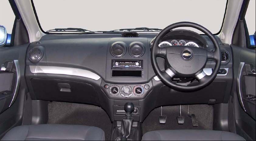
TRAINING                                             General

      Models

     Aveo Hatch
     Aveo         1.6                     L                                       A/C 5DR

     Aveo         1.6                     LS                                         5DR

     Aveo         1.6                     LS                                      A/T 5DR

     Aveo         1.6                     LT                                         5DR

     Aveo Sedan
     Aveo         1.6                    LS                                           4DR

     Aveo         1.6                    LS                                       A/T 4DR

     Aveo         1.6                    LT                                           4DR

 4

                        © 2008 General Motors Corporation. All rights reserved.
General                                TRAINING

Body Styling Changes

For the aveo hatch a facelift has been introduced.
Below are examples of the newly adopted facelift.

                                      Front View

    Noticible changes from the outside of the vehicle are as follows:
●   Honecomb grille replaces lattice grille
●   Aggresively styled front headlight grille assembly
●   Newly adopted gold bowtie badge on front bumper assembly

                                                                                  5

                      © 2008 General Motors Corporation. All rights reserved.
TRAINING                                   General

                                             Rear View

     ●   On the rear bumper you will find a new lower facia insert
     ●   Roof mounted spoiler
     ●   Redesigned taillights to compliment the eye-catching headlight design

 6

                        © 2008 General Motors Corporation. All rights reserved.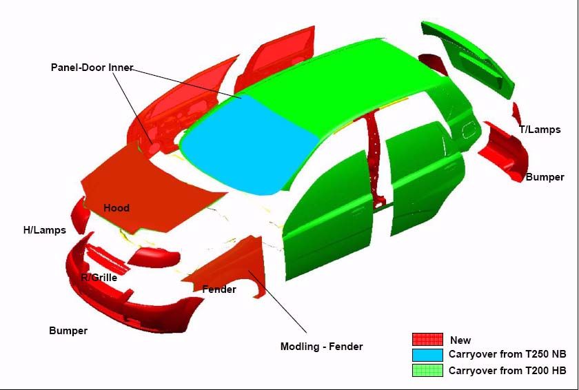
General                                TRAINING

The diagram below indicates the new body panels on the Aveo hatch
and those carried over from the previous model

Changes are as follows:
●   New dashboard fitted across the range
●   Newly designed vent and cluster layout

                                                                                7

                    © 2008 General Motors Corporation. All rights reserved.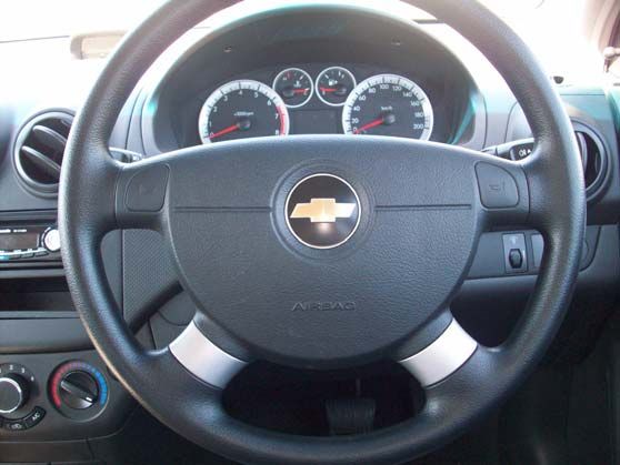
TRAINING General
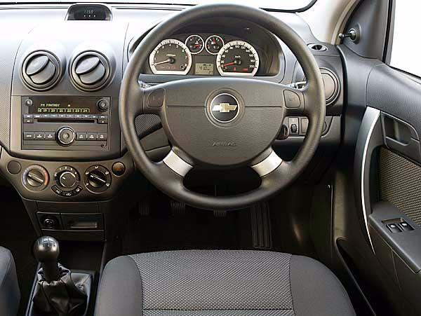
Interior
Some of the key features on the interior:
● Split cupholder on the centre console
● 60/40 rear split seats
● Large pockets behind front seats and side pockets for smaller items
The “new look” instrument cluster incorporates a trip computer indicating the
range for the remaining fuel,the outside temperature, the average fuel econ-
omy and the driving time elapsed.
8
© 2008 General Motors Corporation. All rights reserved.
General                                                                    TRAINING

ENGINE
AVEO HATCH                                  L                    LS                     LS A/T                  LT
Type                                        4 Cyl Transverse     4 Cyl Transverse       4 Cyl Transverse        4 Cyl Transverse
Valve gear/Cylinder Head                    16V DOHC             16V DOHC               16V DOHC                16V DOHC
Bore & Stroke (mm)                          79 x 81,5            79 x 81,5              79 x 81,5               79 x 81,5
Capacity cm³                                1598                 1598                   1598                    1598
Cylinder head material                      Cast Aluminium       Cast Aluminium         Cast Aluminium          Cast Aluminium
Compression Ratio                           9,5 : 1              9,5 : 1                9,5 : 1                 9,5 : 1
Power (kW at r/min)                         77@5800              77@5800                77@5800                 77@5800
Torque (Nm at r/min)                        145@ 3600            145@ 3600              145@ 3600               145@ 3600
Fuel supply                                 (DSI)                (DSI)                  (DSI)                   (DSI)
Fuel requirement                            Unleaded             Unleaded               Unleaded                Unleaded
Emission controls                           Euro II              Euro II                Euro II                 Euro II

TRANSMISSION
AVEO HATCH                                  L                    LS                     LS A/T                  LT
Type                                        5 Speed Manual       5 Speed Manual         4 Speed Auto            5 Speed Manual
Gear Ratios: First                          3,545                3,545                  2,875                   3,545
Second                                      1,952                1,952                  1,568                   1,952
Third                                       1,276                1,276                  1,000                   1,276
Fourth                                      0,971                0,971                  0,697                   0,971
Fifth                                       0,763                0,763                  -                       0,763
Reverse                                     3,333                3,333                  2,300                   3,333
Final drive ratio                           3,944                3,944                  3,836                   3,944

CHASSIS/SUSPENSION
AVEO HATCH                                  L                    LS                      LS A/T                  LT
                                            Independent          Independent McPherson Independent McPherson Independent
Front Suspension
                                            McPhersonStruts      Struts                  Struts                  McPherson Struts
                                            Semi-independent     Semi-independent TorsionSemi-independent TorsionSemi-independent
Rear Suspension
                                            Torsion Beam Axle    Beam Axle               Beam Axle               Torsion Beam Axle

STEERING
AVEO HATCH                                  L                    LS                     LS A/T                  LT
Type                                        Power Assisted       Power Assisted         Power Assisted          Power Assisted
Turning Circle: Wall to Wall (m)            10.06                10.06                  10.06                   10.06
Steering wheel turns, lock-to-lock          3.0                  3.0                    3.0                     3.0

BRAKES
AVEO HATCH                                  L                    LS                     LS A/T                  LT
Front brakes                                Disc vented, 254mm   Disc vented, 254mm     Disc vented, 254mm      Disc vented, 254mm
Rear brakes                                 Drums, 201mm         Drums, 201mm           Drums, 201mm            Drums, 201mm

WHEELS & TYRES
AVEO HATCH                                  L                    LS                     LS A/T                  LT
Rim size                                    14" steel            14" steel              14" steel               14" alloy
Wheel covers                                Standard             Standard               Standard
Size                                        185/60R14            185/60R14              185/60R14               185/60R14
Full size spare wheel                       Standard             Standard               Standard                Standard

DIMENSIONS
AVEO HATCH                                  L                    LS                     LS A/T                  LT
Exterior:Wheelbase (mm)                     2480                 2480                   2480                    2480
Length/ width (mm)                          3920/1680            3920/1680              3920/1680               3920/1680
Height (mm)                                 1505                 1505                   1505                    1505
Interior:Seating capacity                   5                    5                      5                       5
Head room front/ rear                       996/ 955             996/ 955               996/ 955                996/ 955
Legroom front/ rear                         1046/ 897            1046/ 897              1046/ 897               1046/ 897
Shoulder room front/ rear                   1361/ 1339           1361/ 1339             1361/ 1339              1361/ 1339
Ground Clearance (mm)                       150                  150                    150                     150
Tare weight (kg)                            1090                 1100                   1105                    1105
Towing Capacity (kg) (unbraked trailer)     545                  550                    553                     553

CAPACITIES
AVEO HATCH                                  L                    LS                     LS A/T                  LT
Luggage capacity dm³                        198 - 1189           198 - 1189             198 - 1189              198 - 1189
Fuel Tank (litres)                          45                   45                     45                      45

EXTERIOR
AVEO HATCH                                  L                    LS                     LS A/T                  LT
Colour coded bumpers                        Standard             Standard               Standard                Standard
Roof mounted aerial                         Standard             Standard               Standard                Standard
Colour coded exterior mirrors                                    Standard               Standard                Standard
Power exterior mirrors (heated)                                                                                 Standard
Roof spoiler                                                     Standard               Standard                Standard

INTERIOR

                                                                                                                                      _
                                                                                                                                          9

                                     © 2008 General Motors Corporation. All rights reserved.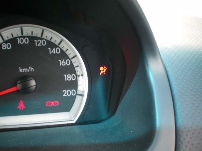
TRAINING                                                          General

  AVEO HATCH                                  L                     LS                         LS A/T                     LT
  Height adjustable driver's seat                                   Standard                   Standard                   Standard
  Adjustable front seat headrests             Standard              Standard                   Standard                   Standard
  Seat back shopping hook                     Standard              Standard                   Standard                   Standard
  Seat fabric, woven standard                 Standard              Standard                   Standard
  Seat fabric, leather                                                                                                    Standard
  60/40 split rear seats                      Standard              Standard                   Standard                   Standard

  STORAGE
  AVEO HATCH                                 L                    LS                         LS A/T                    LT
  Seat back pocket - driver and passenger    Standard             Standard                   Standard                  Standard
  Side pocket in passenger seat              Standard             Standard                   Standard                  Standard
  Dual front cupholders                      Standard             Standard                   Standard                  Standard
  Rear cupholder                             Standard             Standard                   Standard                  Standard
  Folding tray table behind passenger seat                                                                             Standard

  INSTRUMENT CLUSTER
  AVEO HATCH                                 L                     LS                        LS A/T                    LT
  Odometer and trip meter                    Standard              Standard                  Standard                  Standard
  Tachometer                                 Standard              Standard                  Standard                  Standard
  Service indicator                          Standard              Standard                  Standard                  Standard
  Low fuel warning light                     Standard              Standard                  Standard                  Standard
  Door ajar warning light                    Standard              Standard                  Standard                  Standard

  COMFORT & CONVENIENCE
  AVEO HATCH                                 L                     LS                        LS A/T                    LT
  Air conditioner                            Standard              Standard                  Standard                  Standard
  Power steering                             Standard              Standard                  Standard                  Standard
  Radio / SCD                                                      Standard                  Standard                  Standard
  MP3 compatible                                                   Standard                  Standard                  Standard
  Number of speakers                                               4                         4                         6
  Auxiliary Input (Adaptor for iPod & MP3
                                                                   Standard                  Standard                  Standard
  player)
  Roof mounted bee sting antenna             Standard             Standard                   Standard                  Standard
  Cable release for trunk-lid & fuel flap    Standard             Standard                   Standard                  Standard
  Manual window operation                    Standard
  Power windows - front                                            Standard                  Standard                  Standard
  Power windows - front & rear                                                                                         Standard
  Digital clock                              Standard              Standard                  Standard                  Standard
  Front interior courtesy light (incl. door
                                             Standard              Standard                  Standard                  Standard
  activation)
  Front windscreen wipers with intermittent
                                             Standard              Standard                  Standard                  Standard
  wipe function
  Tailgate/ back glass defogger              Standard             Standard                   Standard                  Standard
  Tailgate wiper/ washer                     Standard             Standard                   Standard                  Standard
  Driver and Passenger sun visor with vanity
                                             Standard              Standard                  Standard                  Standard
  mirror
  Tiltable steering column                   Standard             Standard                   Standard                  Standard

  SAFETY
  AVEO HATCH                                  L                     LS                         LS A/T                     LT
  ABS brakes                                  Standard              Standard                   Standard                   Standard
  Collapsible steering column                 Standard              Standard                   Standard                   Standard
  Front fog lamps                                                                                                         Standard
  Airbag driver front                         Standard              Standard                   Standard                   Standard
  Airbag passenger front                                            Standard                   Standard                   Standard
  Central high mounted stop light             Standard              Standard                   Standard                   Standard
  Child seat anchorage provision              Standard              Standard                   Standard                   Standard
  Side impact beams                           Standard              Standard                   Standard                   Standard

  SECURITY
  AVEO HATCH                                 L                     LS                        LS A/T                    LT
  Steering column lock                       Standard              Standard                  Standard                  Standard
  Immobiliser                                Standard              Standard                  Standard                  Standard
  Central door locking                                             Standard - Key operated   Standard - Key operated   Standard - Remote
  Car alarm                                                                                                            Standard

  OPTIONS
  AVEO HATCH                                 L                     LS                        LS A/T                    LT
  Metallic paint                             Free                  Free                      Free                      Free

  SERVICE
  AVEO HATCH                                 L                     LS                        LS A/T                    LT
  Interval                                   15000km/1year         15000km/1year             15000km/1year             15000km/1year
  Warranty                                   3year/100 000km       3year/100 000km           3year/100 000km           3year/100 000km
  Corrosion warranty                         3 Year                3 Year                    3 Year                    3 Year
  Roadside Assistance                        3 Year/ 100 000 km    3 Year/ 100 000 km        3 Year/ 100 000 km        3 Year/ 100 000 km

                                                    _
 10

                                         © 2008 General Motors Corporation. All rights reserved.
Body TRAINING
General Body Construction
Body Safety
Modern stressed-skin bodies are designed so as to have a sturdy passenger cell
protected by front and rear crumple zones
● In an accident the crumple zones are designed to convert impact energy into
deformation work.
● The shape,material and metal thickness must all be precisely matched.
● Many years of experience, refined computational methods and expensive
series of crash tests mean that General Motors now build bodies giving
optimum deformation in the crumple zones in frontal or rear impacts
When repairing body damage, it is therefore imperitive to restore the original struc-
ture and strength in order to guarantee the safety zone of the occupants.
11
© 2008 General Motors Corporation. All rights reserved.TRAINING Body
12
© 2008 General Motors Corporation. All rights reserved.Body TRAINING
Front Hinge Pillar Sectioning
Warning: Sectioning should be performed only in the recommended areas. Failure to do so
may compromise the structural integrity of
the vehicle and cause personal injury if the vehicle is in a collision.
The sedan body side outer panel is available either in one piece or in front or rear portions. The front
and the rear halves are cut about half way across the rear door opening. You can perform any one of
these replacement procedures separately or in any combination, depending upon the extent of dam-
age to the vehicle. Sectioning must take place in specified areas only. Stay away from the door and
window opening radius areas. Section only in straight areas of the openings.
1. Disable the SIR system. Refer to SIR Disabling and Enabling.
2. Disconnect the negative battery cable.
3. Remove all related panels and components.
4. Repair as much of the damaged area as possible. Refer to Dimensions - Body.
5. Remove the sealers and anti-corrosion materials from the repair area, as necessary. Refer to Anti-
Corrosion Treatment and Repair.
Important: Sectioning can be done anywhere in the straight areas of the windshield pillar
and along the rocker panel.
6. Locate the area on the panel where sectioning will be performed.
13
© 2008 General Motors Corporation. All rights reserved.TRAINING Body
7. Measure from any trim attachment hole within the recommended sectioning areas. Mark the
location for section cutting on the vehicle at the windshield pillar and rocker panel locations.
Important: Note the number and location of the factory welds for installation of the hinge pillar.
8. Locate and drill out all factory welds.
Important: Do NOT damage any other panels or reinforcements when cutting at the marked
locations.
9. Cut the panel at the location laid out in the previous steps.
10. Remove the damaged hinge pillar.
14
© 2008 General Motors Corporation. All rights reserved.Body TRAINING
Installation Procedure
1. Locate the area on the service panel where you will perform sectioning.
2. Measure and mark the cut line location on the service part at the same location as on
the vehicle layout.
3. Cut the outer front hinge pillar in corresponding locations to fit the remaining original
panel. The sectioning joint should be trimmed to allow a gap of 1½ times the metal
thickness at the sectioning joint.
4. Create a 50 mm (2 in) backing plate from the unused portion of the service part for the
windshield area.
5. Create a 100 mm (4 in) backing plate from the unused portion of the service part for the
rocker area.
6. Trim the backing plates as necessary to fit behind the panel at the sectioning joint.
Important: If the location of the original plug weld holes can not be determined, space the
plug weld holes every 40 mm (1 1/2 in) apart.
15
© 2008 General Motors Corporation. All rights reserved.TRAINING Body
7. Drill 8 mm (5/16 in) plug weld holes along the sectioning area in the service part, and at
the locations noted from the original panel.
8. Prepare all mating surfaces as necessary.
9. Apply 3M Weld-Thru Coating P/N 05916 or equivalent to all mating surfaces.
10. Fit the backing plates halfway into the sectioning joints, 25 mm (1 in) at the windshield pillar
and 50 mm (2 in) at the rocker panel areas. Clamp the plates in place, and plug weld to the
section joint
11. Position the outer front pillar to the vehicle using 3-dimensional measuring equipment. Clamp
the pillar in place.
12. Plug weld accordingly.
13. Stitch weld the butt weld locations.
14. To create a solid weld with minimum heat distortion, make a 25 mm (1 in) stitch weld
along the seam with gaps of 25 mm. Go back and complete the stitch weld.
15. Clean and prepare all of the welded surfaces.
16. Apply the sealers and anti-corrosion materials to the repair area, as necessary. Refer to
Anti-Corrosion Treatment and Repair.
17. Paint the repaired area. Refer to Basecoat/Clearcoat Paint Systems.
18. Install all of the related panels and components.
19. Connect the negative battery cable.
20. Enable the SIR system. Refer to SIR Disabling and Enabling.
16
© 2008 General Motors Corporation. All rights reserved.Body TRAINING
Quarter Outer Panel Replacement
Removal Procedure
Important: The side panel outer consists of side outer area and frame door area. The side outer
area is a conspicuous part of the outer appearance of the vehicle. It is especially important for
the body line continuing from door. Therefore, pay particular attention to it when conducting
work. This part must be aligned with the rear door, tailgate and other parts.
Warning: Refer to Approved Equipment for Collision Repair Warning in the Preface section.
Warning: Sectioning should be performed only in the recommended areas. Failure to do so may
compromise the structural integrity of vehicle and cause personal injury if the vehicle is
in a collision.
The body side outer panel is available either in one piece or in front or rear portions. The front
and the rear halves are cut about half way across the rear door opening. You can perform any
one of these replacement procedures separately or in any combination,
depending upon the extent of damage to the vehicle. Sectioning must take place in specified
areas only. Stay away from the door andwindow opening radius areas. Section only in straight
areas of the openings.
1. Disable the SIR sytem. Refer to SIR Disabling and Enabling.
2. Disconnect the negative battery cable.
3. Remove all related panels and components.
4. Repair as much of the damaged area as possible. Refer to Dimensions - Body.
5. Remove the sound deadeners as necessary. Note their location.
6. Remove the sealers and anti-corrosion materials from the repair area, as necessary.
17
© 2008 General Motors Corporation. All rights reserved.TRAINING Body
Important: Perform sectioning only in the recommended areas of the rocker panel, dog
leg, sail panel, and upper roof rail area of the body side panel as necessary.
7. Sectioning can be performed at any of the following locations:
Important: Avoid areas in the radius corners for the rear header attachment locations.
• (a) - The butt joint and the weld backer, located on any straight area along the top of
the rear door opening forward of the header panel and rearward of the center pillar
radius. Use a 100-mm (4-in) welding backer.
• (b) - The overlap and the plug weld joint, located 50 mm (2 in) rearward of the last
upper trim attachment slot. This joint will
be an overlap. Cut the service port 10 mm (3/8 in) rearward of the same upper trim
attachment hole.
• (c) - The butt joint and the weld backer, located 75 mm (3 in) down from the lower
edge of the square hole on the exterior panel attachment of the top quarter panel. Use
a 50-mm (2-in) weld backer.
Important: Avoid areas in the lower radius corners, at the bottom of the center pillar,
and at the bottom of the dogleg in the door opening.
• (d) - The butt joint and the weld backer, located on any straight area along the rocker
panel between the door opening. Use a 100mm weld backer.
8. Within the recommended sectioning areas, mark the location of the sectioning cut
lines on the vehicle.
Important: Note the number and location of the factory welds for installation of the
quarter panel.
9. Locate and drill out all factory welds.
Important: Do NOT damage any other panels or reinforcements when cutting at the
marked locations.
10. Cut the panel at the location laid out in the previous steps.
11. Remove the damaged quarter panel.
18
© 2008 General Motors Corporation. All rights reserved.Body TRAINING
Installation Procedure
Important: To allow proper layout and cutting of the service port, review the
appropriate sectioning area information in the removal procedure.
1. Locate the area on the service panel where you will perform sectioning.
2. Measure and mark the cut line location on the service part.
3. Cut the service panel so it will overlap by 30 mm (1.18 in.) in the frame door opening area.
4. Create backing plates of the specified length from the unused portion of the service part.
5. Trim the backing plates as necessary to fit behind the panel at the sectioning joints.
Important: If the location of the original plug weld holes can not be determined, space the plug
weld holes every 40 mm apart.
6. Drill 8 mm plug weld holes along the sectioning areas in the service part. Drill the plug weld
holes 15 mm from the edges.
7. Drill 8 mm plug weld holes at the locations noted from the original panel.
8. Prepare all mating surfaces as necessary.
9. Apply 3M Weld-Thru Coating P/N 05916 or equivalent to all mating surfaces.
10. Fit the backing plates halfway into the sectioning joints on the vehicle. Clamp the plates in
place, and plug weld to the section joint
11. Weld the plug weld holes on the vehicle half of the backing plates.
19
© 2008 General Motors Corporation. All rights reserved.Body TRAINING
12. Position the quarter panel service part to the vehicle using 3-dimensional measuring
equipment. Clamp the quarter panel in place.
13. Plug weld accordingly.
14. To create a solid weld with minimum heat distortion, make a 25 mm (1 in) stitch
weld along the seam with gaps of 25 mm. Go back and complete the stitch weld.
15. Clean and prepare all of the welded surfaces.
16. Apply the sealers and anti-corrosion materials to the repair area, as necessary. Refer
to Anti-Corrosion Treatment and Repair.
17. Paint the repaired area. Refer to Basecoat/Clearcoat Paint Systems.
18. Install all of the related panels and components.
19. Connect the negative battery cable.
20. Enable the SIR system. Refer to SIR Disabling and Enabling.
20
© 2008 General Motors Corporation. All rights reserved.Body TRAINING
Body Lock Pillar Outer Panel Sectioning
Removal Procedure
Important: The frame door opening consist of frame door area and side outer area. It
forms the base for the front, rear doors and other parts and maintains the rigidity of the
doors and roof. The frame door opening area should, depending on the degree of dam-
age,be repaired as much as possible rather than replaced. (Repair by pulling out)
Warning: Sectioning should be performed only in the recommended areas. Failure to do
so may compromise the structural integrity of the vehicle and cause personal injury if
the vehicle is in a collision.
1. The body side outer panel is available in one piece. The front and the rear halves are
cut about half way across the rear door opening. You can perform any one of these
replacement procedures separately or in any combination, depending upon the
extent of the damage to the vehicle. Sectioning must take place in specified areas
only.
Remove all related panels and components.
2. Disable the SIR system. Refer to SIR Disabling and Enabling.
3. Disconnect the negative battery cable.
4. Remove the sealers and anti-corrosion materials from the repair area, as necessary
and note their location. Refer to Anti-Corrosion Treatment and Repair.
5. Repair as much of the damaged area as possible. Refer to Dimensions - Body.
6. At the top of the center pillar, mark a line (a) through the center of the second outer trim
attachment hole.
21
© 2008 General Motors Corporation. All rights reserved.TRAINING Body
7. Measure down 50 mm (2 in) from the mark created in the previous step.
8.Measure from any key feature in the panel. Lay out the cut line location on the body
side panel.
9.Create cut lines on the rocker panel within the approved sectioning locations as
needed.
10.Cut the panel at the center pillar where the lay out line was previously formed.
22
© 2008 General Motors Corporation. All rights reserved.Body TRAINING
11. Cut the panel at the rocker panel area where sectioning is to be performed, within
the straight sections only.
12. Locate and drill out all factory welds. Note the number and location of welds for
installation of the service part.
13. Remove the damaged center pillar.
23
© 2008 General Motors Corporation. All rights reserved.TRAINING Body
Installation Procedure
1. Cut the outer center pillar in corresponding locations to fit the remaining original panel. The
sectioning joint should be trimmed to allow a gap of 1½ times the metal thickness at the sec
tioning joint.
2. In all the rocker panel areas, create a 100 mm (4 in) backing plate from the unused portion of
the service part. Trim the backing plates as necessary to fit behind the sectioning joint.
3. In the upper center pillar area, cut a 50 mm (4 in) backing plate from the unused portion of
the source part trim as necessary.
Important: If the location of the original plug weld holes can not be determined, space the plug
weld holes every 40 mm.
4. Drill 8 mm along the sectioning cuts on the remaining original part. Locate these holes
13mm from the edge of the part and spaced 40 mm apart.
5. Drill 8 mm plug weld holes in the service part as necessary in the corresponding locations
noted on the original panel.
6. Prepare all mating surfaces for welding as necessary.
7. Apply 3M Weld-Thru Coating P/N 05916 or equivalent to all mating surfaces.
8. Fit the backing plates into the sectioning joints for the following distances:
9. Clamp the backing plates in place. Plug weld the backing plates to the vehicle.
10. Position the outer center pillar to the vehicle using 3-dimensional measuring equipment.
Clamp the pillar in place.
11. Plug weld accordingly
24
© 2008 General Motors Corporation. All rights reserved.TRAINING Body
12. To create a solid weld with minimum heat distortion, make a 25 mm (1 in) stitch
weld along the seam with gaps of 25 mm. Go back and complete the stitch weld.
13. Clean and prepare all of the welded surfaces.
14. Apply sound deadening materials as necessary.
15. Apply the sealers and anti-corrosion materials to the repair area, as necessary. Refer
to Anti-Corrosion Treatment and Repair.
16. Paint the repaired area. Refer to Basecoat/Clearcoat Paint Systems.
17. Install all of the related panels and components.
18. Connect the negative battery cable.
19. Enable the SIR system. Refer to SIR Disabling and Enabling.
25
© 2008 General Motors Corporation. All rights reserved.Body TRAINING
Front Compartment Front Rail Replacement
Removal Procedure
Important:
● The front lower rail is joined to the wheelhouse and radiator support, it forms the base for the
front suspension,engine and transmission. Therefore replacement of the component affects
the front wheel alignment and maintains the rigidity of the front section.
● Sectioning procedures have been developed to simplify the repair of the lower rails, as long as
the damage rearward of the sectioning location can be repaired to factory specifications.
● Failure to follow the instructions may lead to improper rail sectioning, which may compromise
the structual integrity of the vehicle
1. Disable the SIR system. Refer to SIR Disabling and Enabling.
2. Disconnect the negative battery cable.
3. Remove all of the related panels and components.
4. Repair as much of the damage as possible to factory specifications.
5. Note the location and remove the sealers and anti-corrosion materials from the repair
area, as necessary. Refer to Anti-Corrosion Treatment and Repair.
6. Perform the necessary procedures to gain access to the repair.
Important: Note the number and location of the factory welds for installation of the full
rail service part.
7. Locate and drill out all the necessary factory welds.
8. Remove the damaged frame rail section (1) from the vehicle.
26
© 2008 General Motors Corporation. All rights reserved.TRAINING Body
Installation Procedure
1. Cut the new frame rail assembly where it will be sectioned align it with the body, then
set the wheelhouse panel.
2. Drill 6 8 mm (5/16 in) plug weld holes in the rail.
3. Clean and prepare all of the welded surfaces.
4. Apply weld-thru coating as necessary. Refer to Anti-Corrosion Treatment and Repair.
5. Inspect the frame measurements 3-dimensional to ensure proper position of the ser
vice rail section.
6. Plug weld accordingly at each plug weld location.
7. Stitch weld along the entire sectioning joint. Make 25 mm (1 in) welds along the seam
with 25 mm (1 in) gaps between.
8. Complete the stitch weld.
9. Clean and prepare all of the welded surfaces.
10. Install all of the related panels and components.
11. Apply the sealers and anti-corrosion materials to the repair area, as necessary. Refer to Anti-
Corrosion Treatment and Repair.
12. Paint the repaired area. Refer to Basecoat/Clearcoat Paint Systems.
13. Connect the negative battery cable.
14. Enable the SIR system. Refer to SIR Disabling and Enabling.
27
© 2008 General Motors Corporation. All rights reserved.Body TRAINING
Anti-Corrosion Treatment and Repair
Warning: When applying sound deadeners, or anti-corrosion materials due care and preventative
measures must be exercised to prevent any material from being sprayed into door and quarter
panel mechanisms such as door locks, window run channels, window regulators and seat belt
retractors, as well as any moving or rotating mechanical or suspension parts on the underbody,
particularly the parking brake cable. After material application, be sure that all body drain holes
are open. Improper application may increase chance of corrosion damage or limit the operation
of moving parts, resulting in personal injury.
Anti-corrosion materials providing rust resistance are used on the interior and the exte-
rior surfaces of the metal panels. These materials include the following metals:
• One-sided galvanized zinc
• Two-sided galvanized zinc
• Zinc-iron alloy steels
These treated metals are
used on the following com-
ponents:
● The fenders
● The doors
● The quarter panels
● The rocker panels
● The lids
● The floor pans
● The wheelhousings
● Other critical part
28
© 2008 General Motors Corporation. All rights reserved.Body TRAINING
Metal conditioners and primers are used on interior and exterior surfaces, along with protective
waxes on the interior surfaces, in the areas where moisture might accumulate. Sealers are
applied along the exposed joints and the moisture-repelling asphaltic sound deadeners are
applied inside the wheel wells, the doors, and on some underbody components.
Any procedure that disturbs these special treatments, such as panel replacement or collision
damage repair operations, may leave the metal unprotected and result in corrosion. Proper
recoating of these surfaces with service-type anti-corrosion material is essential.
Metal conditioners and primer coatings are applied to all metal panels at the time of vehicle man-
ufacture. After repair and/or replacement parts are installed, all accessible bare metal surfaces
must be treated with metal conditioner and reprimed. Refer to the
GM Approved Refinish Materials book GM P/N GM4901M-D which identifies the paint systems
you may use. Always refer to the latest revision of the 4901M-D book. This operation is to be
performed prior to the application of sealers, waxes, deadeners, and anti-rust compounds.
29
© 2008 General Motors Corporation. All rights reserved.Mechanical TRAINING
Engine
The new Chevrolet Aveo boasts an all new 1.6L engine which now uses twin camshafts.
Putting out 77KW of power at 5800RPM and 145 NM of torque at 3400RPM, the 16 valve
engine uses variable valve timing.
It also uses a variable geometry induction system (VGIS) which boasts allround torque.
Variable Geometry Induction System
With a conventional intake manifold if the manifold is longer, low RPM torque goes up and high
RPM torque goes down.The reverse is true if the intake manifold is shorter.A reasonable compro-
mise between the above two cases is the VGIS. In case of low RPM, the intake manifold path
becomes longer and the torque increases. In case of high RPM, the intake manifold path
becomes shorter and the torque increases.
1. High RPM
2. Low RPM
30
© 2008 General Motors Corporation. All rights reserved.TRAINING Mechanical
Transmission
Transmission choice for the new Aveo is a five speed maual gearbox or a four speed automatic
gearbox.
Manual Transmission
Automatic Transmission
31
© 2008 General Motors Corporation. All rights reserved.Mechanical TRAINING
Brake Transmission Shift Interlock
1. The BTSI is a safety device that prevents unintended shift lever movement from th “P”
position into the “R” o “D” range unless the brake pedal is depressed. It functions in all
ignition switch positions.
2. The TCM unlocks the shift lever when the brake ON signal is received.
3. If the BTSI system malfunctions, the shift lever can be moved by inserting the ignition key
into the slot located in the shift console.
32
© 2008 General Motors Corporation. All rights reserved.Mechanical TRAINING
Engine Management System
The Engine Management System makes use of a Engine Control Module (ECM).
This control module is located on the left hand side of the engine compartment, close to the
battery.
33
© 2008 General Motors Corporation. All rights reserved.TRAINING Mechanical
Steering
The power steering system consists of 3 components: the power steering pump, the power
steering fluid reservoir, and the power steering rack and pinion gear. The power steering pump is
a vane-type pump providing hydraulic pressure for the system and is powered by the engine. It
draws on the power steering fluid reservoir, which in turn is connected to the power steering
gear. A pressure-relief valve inside the flow control valve limits the pump pressure.
The energy-absorbing steering column is designed to compress in a front-end collision to lessen
the chance of driver injury.
Caution: The wheels of the vehicle must be straight ahead and the steering column in the LOCK
position before disconnecting the steering column or intermediate shaft from the steering gear.
Failure to do so will cause the coil assembly in the steering column to
become uncentered which will cause damage to the coil assembly.
34
© 2008 General Motors Corporation. All rights reserved.Electrical TRAINING
Data Link Comunications
Data Link Connector(DLC)
Regulations and agreements among the automobile manufacturers have resulted in the stand-
ardization of the data link connector(DLC). The connector is used for the scan tool to access
all vehicle and communications systems. Through it all vehicle system programming is carried
out. The connector can be found under the lower steering wheel panel.
CAN Communication (controller area network)
New Chevrolet Aveo also uses a CAN Bus wiring harness.
The ECM shares some driving information with the TCM for better shifting feels and shifting
points.
ECM TCM
1. Engine RPM 1. Oil Temperature
2. Engine Torque 2.Torque reduction
3. Ignition Timing 3.Gear position
4. A/C ON
35
© 2008 General Motors Corporation. All rights reserved.Electrical TRAINING
Transmission Electrical
Control Driving Mode
The automatic transmission utilizes various shifting modes to control shifting precisely (called
FUZZY CONTROL). Amongst them, “HOLD” mode is selected by pushing the “HOLD” button.
This function holds a certain gear while the shift lever is in drive(D) mode.
FUZZY CONTROL
FUZZY logic is a kind of software program, which assesses driving conditions and decides
which is the proper shifting mode for that condition. Once the logic selected a shifting mode, the
tramsmission would just follow the pre-set shifting schedule. Afterward if driving condition changes,
the fuzzy logic assesses the condition again.It changes the shifting mode accordingly.
Transmission Control Module (TCM)
The TCM primarily controls shift points and lock-up engagement. It has 52 pins with “A,B”
connectors and is located under the instrument panel on the right hand side. Shifting occurs
when solenoids are activated by the TCM.
36
© 2008 General Motors Corporation. All rights reserved.TRAINING Electrical
Diagnostic Lamp (Hold Lamp)
The TCM constantly monitors operation of senors, solenoids and other installed electronic parts.
If a malfunction occurs with any of these parts the hold lamp in the IP will blink. When HOLD
mode is selected by the driver, the HOLD lamp will be ON.
When the ignition switch is turned ON, the HOLD lamp will light for 4 seconds and then go out if
there is no malfunction.If the TCM detects any malfunction of the automatic transmission, the
hold lamp will blink immediately.
Security Indicator
The security indicator is located inside the digital clock on the instrument panel. Once the
system enters the armed mode, the indicator will flash. The indicator cycles by turning on for
0.125 sec and off for0.875 sec. until the control module/receiver is disarmed.
Alarm status
37
© 2008 General Motors Corporation. All rights reserved.TRAINING Electrical
Siren
The alarm is sounded by means of the vehicle’s horn, which is located on the left hand side at
the front of the vehicle, behind the grille. If equipped with a siren, it would be located beside
th ECM in the engine compartment.
Keyless entry control module/Receiver
The remote keyless entry control module/ receiver is located in the middle, under the dash board. The con-
trol module/ receiver activates the alarm if an intrusion is detected.
The control module also has a self-diagnostic function. In order to display trouble codes, the scan tool must
be connected to the Data Link Connector. The control module will not communicate with transmitters
from other vehicles because there are over four billion possible electronic password combinations and
the passwords cannot be duplicated.
The control module has an attached antenna to detect signals from the transmitter.
38
© 2008 General Motors Corporation. All rights reserved.Restraint System TRAINING
Supplemental Restraint System (SRS)
The Supplemental Restraint System (SRS) is a safety device used in conjunction with the seat
belts.Passengers must fasten their seat belts and adjust them for safety. The SRS is
designed to protect the passengers in the event of the significant frontal or side impact to
the vehicle.
Generally, the SRS consists of:
● Front airbag modules
● Side airbag modules
● Sensing and diagnostic module (SDM)
● Side impact sensors
● Seat belt pretensioner
● Steering wheel coil module
● Wiring harness
● Airbag warning lamp
Operation in a frontal impact
Inside the SDM there are two sensors for front airbag deployment triggering.One is the elec-
tronic accelerometer. The other is the mechanical safing sensor. The accelerometer continu-
ously measures the vehicle’s acceleration, and delivers the signals to the microprocessor of
the SDM. The sophisticated crash signal processing algorithms in the microprocessor deter-
mine whether deployment is needed or not.If deployment is needed, the microprocessor acti-
vates the firing circuits. Even if the microprocessor determines that deployment of the airbag
is necessary and sends the firing signal to the airbag modules, the airbag modules will not
deploy until the safing sensor closes the firing circuit switch by mechanical impact.
Application Description
Deployment Time >20 ms
Detection Time >5 ms
Airbag Replacement interval Every 10 years after installation
Voltage range 8-16 V
Acceleration Range +/- 50 G
Energy Reserve Duration 150 ms after battery disconnection
Airbag Warning Lamp On Time 7 sec
39
© 2008 General Motors Corporation. All rights reserved.Restraint System TRAINING
Component Location
40
© 2008 General Motors Corporation. All rights reserved.TRAINING Restraint System
Sensing and Diagnostic Module
The SDM intergrates the following components:
● Crash sensor & safing sensor:Detects the impact (crash event)
● Control circuit: Analyzes the impact input and determines air bag deployment.
● Power reserve circuit: Backs up the power supply in case of power loss.
● Voltage modulation circuit: Increases the voltage needed for the deployment.
● Air bag warning lamp circuit: Alert the driver of the malfunction.
● Diagnostic interface: Communicates with the Scan tool
Location
The SDM is located under the center console in front of the hand brake assembly.
41
© 2008 General Motors Corporation. All rights reserved.Restraint System TRAINING
Frontal Airbags
The front airbags include:
● The driver side airbag module: 60 L
● The passenger side airbag module: 120 L
Location
● Driver side airbag module: Under the center pad of the steering wheel.
● Passenger side airbag module: On the passenger side of the instrument Panel.
42
© 2008 General Motors Corporation. All rights reserved.TRAINING Restraint System
Side Airbags
Seperate left and right side impact sensors, which are external parts of the SDM, trigger the
inflation of side airbags by left or right side impacts respectively.The safing sensor that mechani-
cally intervenes in frontal airbag operation is not related to the side airbag inflation.
Location: Inside th front seat backrest
Airbag Volume: 21L
Side Impact sensors
The side impact sensors are installed at the bottom, inside the B pillars.They provide side impact
signals to the SDM
43
© 2008 General Motors Corporation. All rights reserved.Restraint System TRAINING
Seatbelt Pretensioners
The left and right front seat belt pretensioners are assembled as part of the front seat belt
retractor. They retract the seat belt webbing during a frontal collision. The seat belt preten-
sioners are optional systems controlled by the SDM.
Location: Inside the centre Pillars
The seat belt pretensioners also contains an igniter charge and a gas generator, which tight-
ens the seat belt webbing. The seat belt pretensioner must be replaced after any activa-
tion.
44
© 2008 General Motors Corporation. All rights reserved.TRAINING Restraint System
Steering Wheel Coil Module
The Steering Wheel Coil Module is installed between the steering column and the steering wheel.
It is a wiring harness connecting the air bag module and the air bag wiring harness. While the
steering wheel rotates left and right, the internal wire of the steering wheel coil Module winds
and unwinds so that it connects the airbag and the horn switch to the wiring harness. The neu-
tral position should be set before installing the Steering Wheel Coil Module, because its rota-
tion is restricted to +- 3 turns.The Steering Wheel Coil Module should not be disassembled. It
should be replaced if the airbag has been deployed.
Installing the Steering Wheel Coil Module
● Align the vehicle wheels straight ahead.
● Turn the contact coil clockwise fully.
● Turn the contact coil counter - clockwise 3 turns and align “arrow” marks.
Notice: Do not rotate the steering wheel or move the position of the steering gear once the
intermediate shaft is disconnected. This will uncenter the inflatable Restraint coil in the steer-
ing column. If the inflatable restraint coil becomes uncentered, it may be damaged during vehi-
cle operation.
45
© 2008 General Motors Corporation. All rights reserved.TRAINING
SRS Trouble Codes
If the SDM detects any problem, it will illuminate the airbag - lamp and store diagnostic trouble
codes. The stored trouble codes can be read by the Scan Tool and is the only way to check
these codes. The trouble codes should be erased by the Scan Tool after the problem has been
solved.
1. Trouble code are classified according to whether they are currently active or previously active.
● Active codes: Trouble codes currently exist
● History codes: Trouble codes were present earlier but do not exist currently.
2. Trouble codes are also classified as follows:
● SDM internal troubles
● SDM external troubles
● Airbag inflation records
3. The SDM should be replaced when the stored trouble codes can not be erased.
Once the frontal airbag is inflated, the SDM should be replaced. The SDM can be re-used after the side air-
bags and seatbelt pretensioners have deployed up to 5 times.
However, it is recommended that the SDMbe replaced in the case of serious collisions, because the SDM
could be damaged internally.
46
© 2008 General Motors Corporation. All rights reserved.Body TRAINING
Airbag Warning Lamp
The airbag warning lamp is located in the instrument cluster and alerts the driver of system
malfunctions.
When the ignition key is turned on , the warning lamp flashes 7 times for 7 seconds. If the
system is normal it goes OFF. If there is a malfunction it will stay ON continuously.
47
© 2008 General Motors Corporation. All rights reserved.TRAINING Notes
....................................................................................................................................................
.....................................................................................................................................................
....................................................................................................................................................
.....................................................................................................................................................
....................................................................................................................................................
.....................................................................................................................................................
....................................................................................................................................................
.....................................................................................................................................................
....................................................................................................................................................
.....................................................................................................................................................
....................................................................................................................................................
.....................................................................................................................................................
....................................................................................................................................................
.....................................................................................................................................................
....................................................................................................................................................
.....................................................................................................................................................
....................................................................................................................................................
.....................................................................................................................................................
....................................................................................................................................................
.....................................................................................................................................................
....................................................................................................................................................
.....................................................................................................................................................
48
© 2008 General Motors Corporation. All rights reserved.You can also read