R&SRTE Digital Oscilloscope Scope of the art

Page created by Stanley Casey
 
CONTINUE READING
R&SRTE Digital Oscilloscope Scope of the art
R&S®RTE
      Digital Oscilloscope
      Scope of the art

                                         Test & Measurement

                                                              Product Brochure | 01.00

RTE_bro_en_3606-9033-12.indd 1   03.03.2014 08:57:33
R&SRTE Digital Oscilloscope Scope of the art
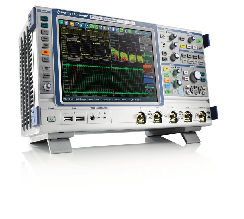
R&S®RTE                                                       Besides the cursor functions and automated measure-
                                                                   ments, the R&S®RTE offers even more analysis tools that
                                                                   help users to complete tasks quickly. At the push of a but-

     Digital Oscilloscope                                          ton, for example, the QuickMeas function simultaneously
                                                                   displays the results of multiple measurement functions for
                                                                   the signal that is currently active. The FFT analysis is also

     At a glance                                                   unique. It gives the impression of a live spectrum on the
                                                                   screen and reliably detects sporadic signals.

                                                                   A broad range of dedicated application solutions is also
      More reliable measurements, more tools and fast              available, including trigger and decode options for serial
      results, more fun to use – that’s the R&S®RTE                buses such as I2C, SPI and CAN, and a power analysis op-
                                                                   tion. The logic analysis capability offered by the R&S®RTE
      oscilloscope. From embedded design development
                                                                   is essential for analyzing digital components of embed-
      to power electronics analysis to general debugging,          ded designs. The R&S®RTE-B1 mixed signal option can
      the R&S®RTE offers quick solutions for everyday              be added to any base unit and offers 16 additional digital
      T & M tasks.                                                 channels. It is possible to decode up to four parallel buses
                                                                   simultaneously.

      The R&S®RTE oscilloscopes are available with two or          The wide variety of measurement and analysis functions
      four channels and a bandwidth of 200 MHz, 350 MHz,           can be easily operated via the high-resolution 10.4" XGA
      500 MHz or 1 GHz. With a sampling rate of 5 Gsample/s        touchscreen. Transparent dialog boxes ensure that the
      and a memory depth of 10 Msample per channel (can be         measurement diagrams always maintain their original size.
      optionally expanded to 50 Msample per channel), the in-      Signal flow diagrams in the dialog boxes simplify naviga-
      struments provide excellent performance parameters.          tion. Signal icons with realtime preview on the edge of the
                                                                   screen clearly show what is currently happening.
      An acquisition rate of more than one million waveforms
      per second ensures that signal faults are found quickly.     The R&S®RTE handles challenges quickly, accurately and
      A highly accurate digital trigger system and the excellent   easily, providing time domain, logic, protocol and fre-
      dynamic range of the A/D converter with its more than        quency analysis in a single box. The R&S®RTE expands the
      seven effective bits provide precise results.                Rohde & Schwarz scope-of-the-art oscilloscope family.

      2

RTE_bro_en_3606-9033-12.indd 2                                                                                                03.03.2014 08:57:35
R&SRTE Digital Oscilloscope Scope of the art
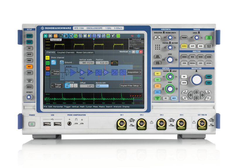
R&S®RTE                                                     Logic analysis with the MSO option
                                                                         ❙❙ More signal details thanks to high time resolution across
                                                                            the entire memory depth

             Digital Oscilloscope                                        ❙❙ Precise triggering on signal events
                                                                         ❙❙ High acquisition and analysis rate for fast fault finding
                                                                         ❙❙ Straightforward display of digital signals

             Benefits and                                                ❙❙ Analysis functions
                                                                         ❙❙ Analysis of serial protocols, even with digital channels
                                                                         ❙❙ Low test point loading due to active probe solution

             key features                                                ▷▷ page 10

                                                                         Serial protocols: easy triggering and decoding
                                                                         ❙❙ Fast measurement configuration
              More confidence in measurement results                     ❙❙ Isolating protocol events
              ❙❙ High time resolution combined with deep memory          ❙❙ Clear display of data
              ❙❙ Finding rare signal faults quickly                      ❙❙ High acquisition rate for finding errors quickly
              ❙❙ Accurate triggering using a digital trigger system      ▷▷ page 12
              ❙❙ Precise measurements due to single-core A/D converter
              ❙❙ Full measurement bandwidth, even at 1 mV/div            Power analysis
              ▷▷ page 4                                                  ❙❙ Special measurement functions and measurement wizard
                                                                            for fast results
              More functions and faster results                          ❙❙ Standards for limiting the harmonic current
              ❙❙ High measurement speed, even for complex analysis       ❙❙ Easy, clear documentation of measurement results
                 functions                                               ❙❙ Extensive accessories for contacting and delay
              ❙❙ Wide selection of measurement functions                    compensation
              ❙❙ QuickMeas: key measurement results at the push of a     ▷▷ page 14
                 button
              ❙❙ History function: looking back in time                  EMI debugging with oscilloscopes
              ❙❙ Mask test: settings in only seconds                     ❙❙ EMI tests during development
              ❙❙ FFT: the easy way to analyze the signal spectrum        ❙❙ High dynamic range and sensitivity
              ▷▷ page 6                                                  ❙❙ Visualizing sporadic emissions
                                                                         ❙❙ Correlation between frequency and time
              More fun to use                                            ▷▷ page 16
              ❙❙ Straightforward, smart user guidance
              ❙❙ Fully customizable display                              High-performance probes with extensive
              ❙❙ High-resolution touchscreen                             accessories
              ❙❙ Fast access to important tools                          ❙❙ The Rohde & Schwarz probe family
              ❙❙ Signal details at your fingertip                        ❙❙ High signal fidelity due to excellent specifications
              ▷▷ page 8                                                  ❙❙ Easy operation: rugged and ergonomical
                                                                         ❙❙ Micro button for convenient instrument control
                                                                         ❙❙ R&S®ProbeMeter: integrated voltmeter for precise DC
                                                                            measurements
                                                                         ▷▷ page 18

                                                                         Secure investment thanks to easy extensibility
                                                                         ❙❙ On-site installation of hardware options
               Models                                                    ❙❙ Software applications on demand
               Base unit          Bandwidth             Channels
                                                                         ❙❙ Free firmware updates
               R&S®RTE1104        1 GHz                 4
                                                                         ❙❙ Bandwidth upgrades, including calibration
               R&S®RTE1102        1 GHz                 2
                                                                         ▷▷ page 21
               R&S®RTE1054        500 MHz               4
               R&S®RTE1052        500 MHz               2
               R&S®RTE1034        350 MHz               4
               R&S®RTE1032        350 MHz               2
               R&S®RTE1024        200 MHz               4
               R&S®RTE1022        200 MHz               2

                                                                                            Rohde & Schwarz R&S®RTE Digital Oscilloscope 3

RTE_bro_en_3606-9033-12.indd 3                                                                                                  03.03.2014 08:57:36
R&SRTE Digital Oscilloscope Scope of the art
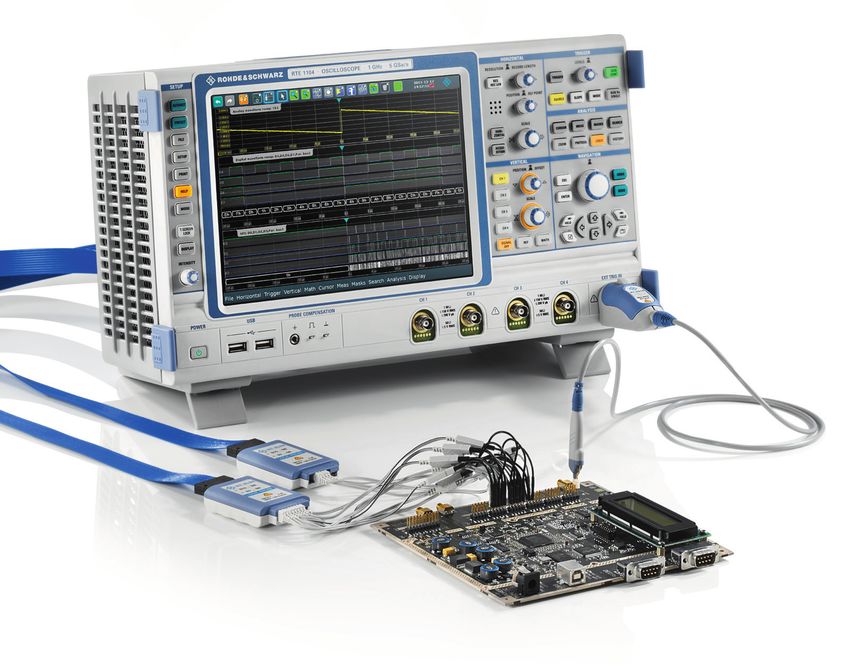
More confidence                                                    The R&S®RTE offers a combination of sampling rate and
                                                                        memory depth that is unique in this class. A sampling
                                                                        rate of 5 Gsample/s at a memory depth of 10 Msample

     in measurement                                                     is available per channel (can be optionally expanded to
                                                                        50 Msample per channel).

     results                                                            Finding rare signal faults quickly
                                                                        The acquisition cycle of a digital oscilloscope consists of
                                                                        two steps. First, the oscilloscope samples the signal and
                                                                        stores the samples. In a second step, it processes these
      Rohde & Schwarz has many years of experience                      samples and displays the waveform on the screen. During
      in the development of precision test and                          this period, the oscilloscope is “blind” to the signal. Sig-
                                                                        nal faults that occur during this blind time remain hidden
      measurement equipment, which also benefits the
                                                                        to the user. The less often signal faults occur, the longer
      R&S®RTE oscilloscopes. They offer tried and tested                it can take to detect them. This makes high acquisition
      Rohde & Schwarz quality for meeting stringent                     rate and short blind time critical. The core of the R&S®RTE
      requirements.                                                     oscilloscope is an ASIC that was especially designed for
                                                                        parallel processing. As a result, the R&S®RTE can acquire,
                                                                        analyze and display more than one million waveforms per
      High time resolution combined with deep memory                    second without a special acquisition mode. The high ac-
      The more details an oscilloscope can show, the higher the         quisition rate makes it possible to find signal faults faster
      probability that the user will be able to analyze signal faults   and more reliably, effectively shortening debugging time.
      or important events. As a prerequisite, the oscilloscope
      must have a high time resolution that is based on a high
      sampling rate. In addition, many applications also require
      long record lengths, for instance for analyzing the tran-
      sients of switched-mode power supplies or the data con-
      tent of serial protocols. In order to maintain a high sam-
      pling rate even for long signal sequences, the oscilloscope
      requires a deep memory.

                                                                                             Due to the high acquisition rate of
                                                                                             one m
                                                                                                 ­ illion waveforms per second, the
                                                                                             R&S®RTE oscilloscopes find rare signal faults
                                                                                             very quickly.

      4

RTE_bro_en_3606-9033-12.indd 4                                                                                                               03.03.2014 08:57:36
R&SRTE Digital Oscilloscope Scope of the art
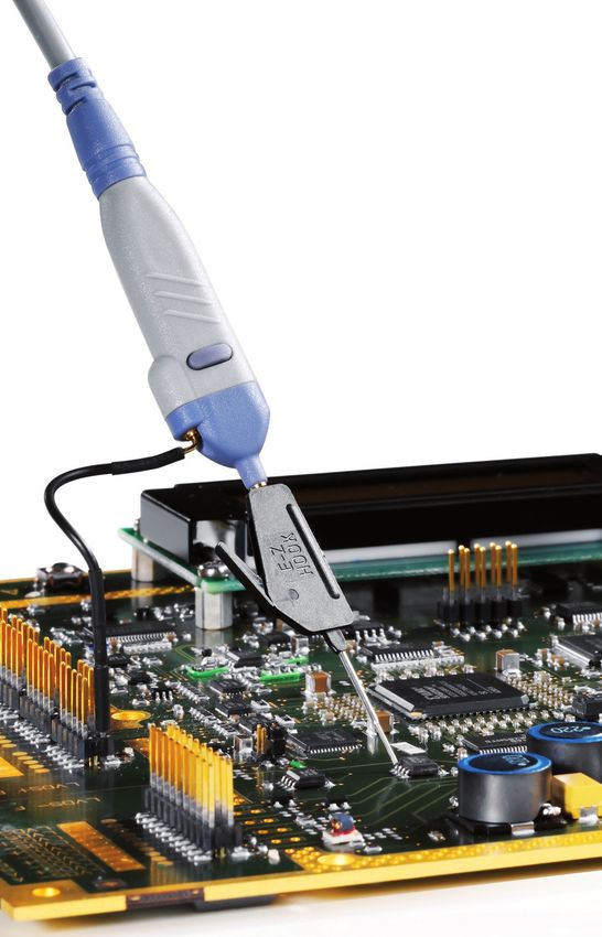
Accurate triggering using a digital trigger system                                              Precise measurements due to single-core A/D
              The unique Rohde & Schwarz digital trigger system is also                                       converter
              used in the R&S®RTE oscilloscopes. It consists of only one                                      The accuracy of signal digitization depends on the A/D
              common path for acquisition signal and trigger signal. The                                      converter's effective number of bits (ENOB). Especially the
              instruments determine if the trigger condition has been                                         small signal amplitudes of high-speed digital interfaces, or
              met by directly analyzing the digitized signal independently                                    signal analysis in the frequency domain, place more strin-
              of the current sampling rate. As a result, Rohde & Schwarz                                      gent requirements on the dynamic range.
              oscilloscopes have an extremely low trigger jitter and a
              high measurement accuracy.                                                                      Traditionally, 8-bit A/D converters have been used in digital
                                                                                                              oscilloscopes. These converters consist of multiple slow
              The digital trigger increases the oscilloscope's trigger                                        time-interleaved converters that are connected. However,
              sensitivity because it can validate every acquired sample                                       the higher the number of components that are combined,
              against the trigger definition. The R&S®RTE is able to trig-                                    the larger the errors that arise due to the fact that the be-
              ger on even the smallest signal amplitudes.                                                     havior of the individual converters is not uniform.

              In addition, the digital trigger system permits the user to                                     Rohde & Schwarz developed a monolithic A/D converter.
              adjust the trigger hysteresis to the signal quality, ensuring                                   This chip's single-core architecture minimizes signal distor-
              consistently reliable and stable triggering.                                                    tion and achieves more than seven effective bits (ENOB).

              Another innovation is the flexible adjustment of the cut-                                       Full measurement bandwidth, even at 1 mV/div
              off frequency of the digital lowpass filter. The same filter                                    With their input sensitivity of up to 1 mV/div, the R&S®RTE
              settings can be used for both the trigger signal and the                                        oscilloscopes offer high vertical resolution. Other oscillo-
              measurement signal. As a result, RF noise on the trigger                                        scopes attain such high input sensitivity only by employ-
              signal can be suppressed, for instance, while simultane-                                        ing software-based zooming or by limiting the bandwidth.
              ously capturing and displaying the unfiltered measurement                                       The R&S®RTE oscilloscopes, however, show a signal's real
              signal.                                                                                         sampling points even at 1 mV/div, at full measurement
                                                                                                              bandwidth. This high measurement accuracy is particularly
                                                                                                              beneficial when measuring small signal amplitudes.

               Comparison of digital and analog triggering architecture

                                                                                                                                      Memory

                       Channel input                 Vertical system                 A/D converter                   Acquisition                     Processing           Display

                                                                                    Analog trigger                                 Digital trigger

                   The analog triggering architecture consists of two separate signal paths for the acquisition signal and the trigger.
                   However, these different signal paths cause time and amplitude offset, which results in measurement inaccuracies.
                   The digital trigger concept of the R&S®RTE oscilloscopes with only one path keeps trigger jitter at very low levels.

                                                                                                                                           Rohde & Schwarz R&S®RTE Digital Oscilloscope 5

RTE_bro_en_3606-9033-12.indd 5                                                                                                                                                  03.03.2014 08:57:36
R&SRTE Digital Oscilloscope Scope of the art
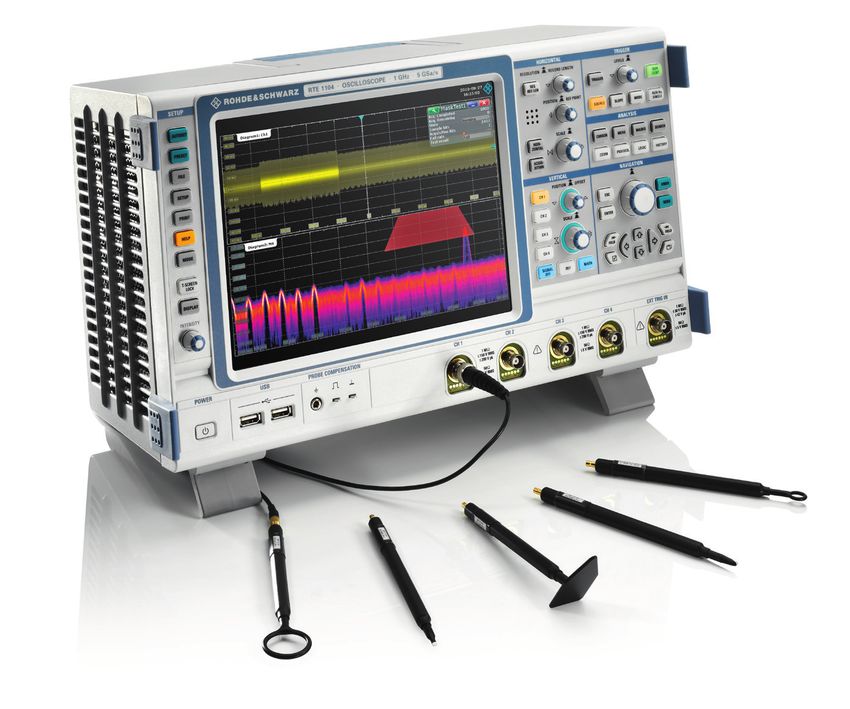
More functions and                                                      High measurement speed, even for complex
                                                                             analysis functions
                                                                             In the R&S®RTE oscilloscopes, many measurement func-

     faster results                                                          tions are hardware-implemented:
                                                                             ❙❙ Histogram
                                                                             ❙❙ Spectrum display
                                                                             ❙❙ Mask test
      The R&S®RTE includes many integrated                                   ❙❙ Cursor measurements
      measurement tools for detailed signal analysis. They                   ❙❙ Selected automatic measurement functions
                                                                             ❙❙ Selected mathematical operations
      range from simple cursor functions to mask tests to
      complex mathematical operations. The results are                       As a result, the acquisition and processing rate remains
      available quickly and are based on a large number                      high, even when analysis functions are active. The oscil-
      of waveforms that provide statistically meaningful                     loscope enables smooth work, and even complex test se-
      information.                                                           quences are available quickly, making a statistically mean-
                                                                             ingful analysis possible.

                                                                             Wide selection of measurement functions
                                                                             A key feature of digital oscilloscopes are automatic mea-
                                                                             surements. They permit users to determine the charac-
                                                                             teristics of a signal quickly and easily. This can be simple
                                                                             measurement of signal characteristics such as frequency
                                                                             and rise and fall times or complex analysis such as deter-
                                                                             mining the switching loss of a switched-mode power sup-
                                                                             ply. The R&S®RTE displays the results of up to eight mea-
                                                                             surements simultaneously. Automated measurements are
                                                                             divided into four different categories: amplitude and time
                                                                             measurements, histogram measurements, eye diagram
                                                                             measurements and spectral measurements. A total of 78
                                                                             measurement functions are available. The gating function
                                                                             can be used to limit these functions to a specific signal
                                                                             range. The user can easily define this range on the screen
                                                                             using a finger or the mouse, or link it to existing cursor or
                                                                             zoom ranges.

                                                                             QuickMeas: key measurement results at the push
                                                                             of a button
                                                                             The QuickMeas function offered by the R&S®RTE oscillo-
                                                                             scopes is unique in this class. The results of multiple mea-
                                                                             surement functions are simultaneously displayed for the
                                                                             currently active signal. Depending on the requirements,
      In the R&S®RTE oscilloscopes, up to eight automatic measurements can   the set of functions can be individually defined with up
      be configured and activated simultaneously.                            to eight measurements and saved for later analysis. The
                                                                             QuickMeas function is quickly and easily accessed via the
                                                                             toolbar.

      6

RTE_bro_en_3606-9033-12.indd 6                                                                                                          03.03.2014 08:57:36
R&SRTE Digital Oscilloscope Scope of the art
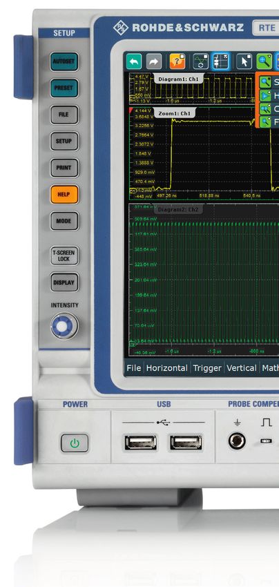
History function: looking back in time                                         The history function can also be used in ultra-segmented
              Where does the interference pulse in the signal come                           mode. The oscilloscope performs a predefined number
              from? What caused the loss of a data bit? Finding the real                     of acquisitions without interruption. The waveforms are
              cause of a problem is often only possible by looking at the                    displayed on the screen only after the last acquisition has
              history of a signal sequence.                                                  been captured. The history player can be used to analyze
                                                                                             the individual acquisitions. This mode has the advantage
              The R&S®RTE history function always provides access                            of an even shorter blind time (< 300 ns) between the indi-
              to previously acquired waveforms. This enables the user                        vidual acquisitions.
              to immediately analyze the measurement data stored in
              memory. Users can scroll through the individual acqui-                         Mask test: settings in only seconds
              sitions with the history player or display them in super-                      Mask tests quickly reveal whether a specific signal lies
              imposed form in persistence mode. One timestamp per                            within defined tolerance limits and use statistical pass/fail
              waveform makes it possible to clearly identify when the                        evaluation to assess the quality and stability of a device
              event took place. All analysis tools offered by the R&S®RTE                    under test. Signal anomalies and unexpected results are
              are available for analyzing past acquisitions.                                 easy to identify by stopping the measurement if the mask
                                                                                             is violated.

                                                                                             Defining masks is easy and flexible with the R&S®RTE.
                                                                                             With just a few keystrokes, the user can generate a mask
                                                                                             from a reference signal or define masks consisting of up
                                                                                             to 16 segments. To get started quickly, the mask segments
              The R&S®RTE masks consist of up to 16 segments. Hardware implementa-           can be generated on the screen using the mouse or a fin-
              tion keeps the acquisition rate high, and mask violations are quickly found.   ger. Later on, the positions of the mask points can be opti-
                                                                                             mized in the mask test dialog box.

                                                                                             FFT: the easy way to analyze the signal spectrum
                                                                                             Thanks to hardware implementation, the FFT in the
                                                                                             R&S®RTE is very fast. The high acquisition and postpro-
                                                                                             cessing rate conveys the impression of a live spectrum.
                                                                                             Using the persistence mode, rapid signal changes, sporad-
                                                                                             ic signal interference and weak superimposed signals can
                                                                                             easily be made visible. The ability to overlap FFT frames
                                                                                             enables the R&S®RTE to detect intermittent signals such as
                                                                                             pulsed interferers.

                                                                                             Just like in spectrum analyzers, FFT operation is based on
                                                                                             entering the center frequency, span and resolution band-
                                                                                             width. The labeled axial scaling is especially user-friendly.

              The R&S®RTE FFT function offers accuracy, speed, functionality and ease
              of use.

                                                                                                                Rohde & Schwarz R&S®RTE Digital Oscilloscope 7

RTE_bro_en_3606-9033-12.indd 7                                                                                                                      03.03.2014 08:57:37
R&SRTE Digital Oscilloscope Scope of the art
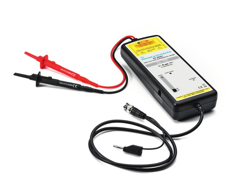
More fun to use                                                               Fully customizable display
                                                                                   When working with multiple signals, the screen becomes
                                                                                   easily cluttered. R&S®RTE oscilloscopes are different:
                                                                                   They display the waveforms and measurement results
      The R&S®RTE oscilloscopes unite established                                  in realtime in the form of signal icons on the edge of
      concepts with new features and turn user wishes                              the screen. These miniature views can be dragged and
                                                                                   dropped onto the main screen. When multiple waveforms
      into reality: Just unpack the instrument, switch it on
                                                                                   are to be displayed simultaneously, the Rohde & Schwarz
      – and measure.                                                               SmartGrid function helps the user to keep the screen well
                                                                                   organized by flexibly dividing it into several diagrams.
                                                                                   ­Individual waveforms can be displayed in a clear, well-
      Straightforward, smart user guidance                                          structured manner. The A/D converter range is optimally
      Different tools make operation of the R&S®RTE fast and                        used for highest accuracy.
      easy, leading quickly to the desired measurement results.

      The controls for vertical settings and the trigger are color-
      coded. Multicolor LEDs around the rotary knobs visualize
      the channel that is currently in focus. This color-coding
      corresponds to the signal display on the screen. This clear
      mapping allows smooth work, even during complex test
      and measurement tasks.                                                       Control elements of the R&S®RTE oscilloscopes

      Signal flow diagrams in the dialog boxes visualize signal
      processing; crosslinks lead directly to logically related set-
      tings. Forward and back buttons help to navigate quickly                      Toolbar for
                                                                                    fast access to
      between dialog boxes.
                                                                                    frequently used functions

      Semi-transparent dialog boxes are an elegant way to keep                      Tools that have a
                                                                                    similar function are grouped
      everything in view. The measurement diagrams always
                                                                                    together
      maintain their original size. The level of transparency can
      be set via the intensity button. In addition, users are able
      to scale the dialog boxes and position them anywhere on                       Clear numeric grid
                                                                                    annotation for easy
      the screen.                                                                   reading of measured values

                                                                                    Rohde & Schwarz
                                                                                    SmartGrid function for
                                                                                    quickly positioning the
                                                                                    waveforms

                                                                                    Knob for setting the level of
                                                                                    transparency of the
                                                                                    dialog boxes or the intensity
                                                                                    of the waveforms

                                                                                    Menu bar on the
                                                                                    bottom edge of the screen
                                                                                    – even visible during
                                                                                    ­touchscreen operation

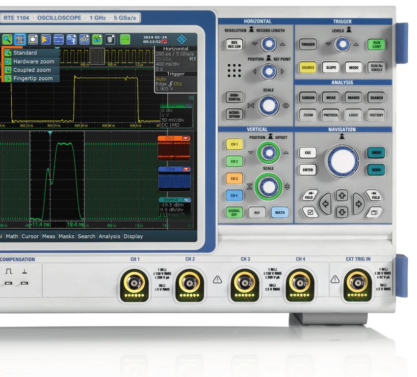
                                 Depending on user preferences, the R&S®RTE
                                 oscilloscopes can be operated via buttons, the                                               USB interfaces for mouse,
                                 mouse or the touchscreen. When activating                                                    keyboard, data exchange,
                                                                                                                              documentation or firmware
                                 multiple diagrams, the SmartGrid function helps                                               updates
                                 the user to optimally set up the screen.

      8

RTE_bro_en_3606-9033-12.indd 8                                                                                                                  03.03.2014 08:57:38
R&SRTE Digital Oscilloscope Scope of the art
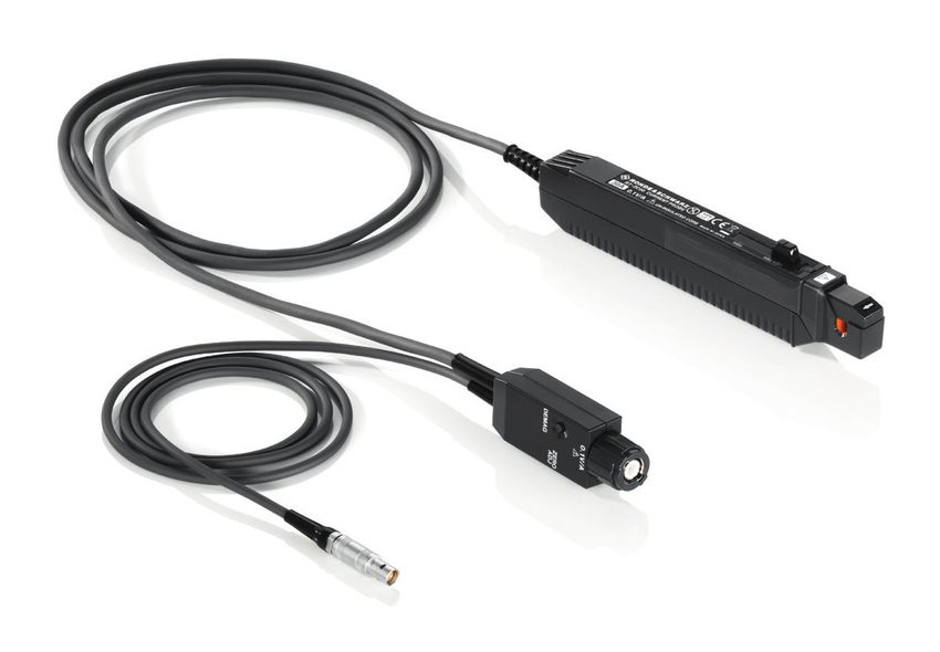
High-resolution touchscreen                                              Signal details at your fingertip
              The high-resolution 10.4" XGA touchscreen is one of the                  Zoom is a standard tool of digital oscilloscopes for ana-
              highlights of the R&S®RTE oscilloscope. It supports touch                lyzing the details of a captured signal. In addition to the
              operation for all functions. Signals can be dragged and                  standard zoom function, the R&S®RTE offers an additional
              dropped onto the screen, the measurement range can be                    highlight, the fingertip zoom. If this function is selected,
              defined using a finger, and dialog boxes can be scaled and               a single click on the screen opens a horizontal zoom for
              positioned on the screen as required.                                    the signal. By moving the zoom window along the signal
                                                                                       using the fingertip or the mouse, the user obtains a quick
              Fast access to important tools                                           overview of the signal characteristics. A normal zoom can
              A toolbar at the upper edge of the screen provides ac-                   be opened for detailed analysis of anomalies.
              cess to frequently used functions such as measurements,
              zoom, FFT and recycle bin. The toolbar can be custom-
              ized to contain the user’s favorite tools. There are just two
              steps involved in using a function: selecting the tool and
              applying it to the waveform.

                                                                                                                               Standard zoom for horizontal
                                                                                                                               and vertical zooming

                                                                                                                               Direct access to
                                                                                                                               frequently required
                                                                                                                               analysis functions

                                                                                                                               Signal icons show
                                                                                                                               ­important settings or a
                                                                                                                                miniature view of the real
                                                                                                                                signal

                                                                                                                               Multilevel undo/redo
                                                                                                                               function for easily reverting
                                                                                                                               to previous settings

       Fingertip zoom: Move the finger                           Color-coded elements for
       along the signal to get a quick                           visualizing the channel that is
       overview of signal details                                currently selected

                                                                                                         Rohde & Schwarz R&S®RTE Digital Oscilloscope 9

RTE_bro_en_3606-9033-12.indd 9                                                                                                                     03.03.2014 08:57:41
R&SRTE Digital Oscilloscope Scope of the art
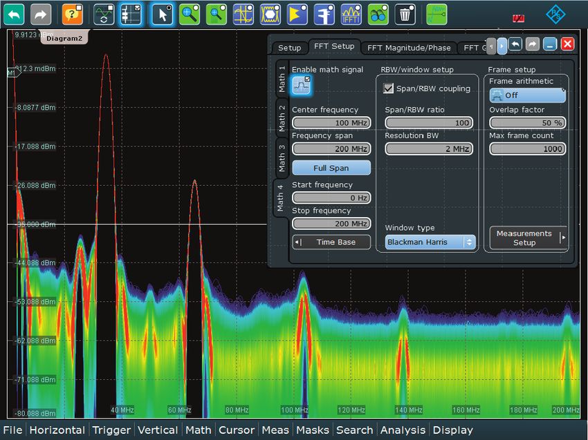
Logic analysis with                                             High acquisition and analysis rate for fast fault
                                                                     finding
                                                                     Signal processing of the digital waveforms is done in

     the MSO option                                                  hardware. This extends from acquisition and triggering to
                                                                     analysis functions such as cursor functions and measure-
                                                                     ments, and even includes the visualization of the results.
                                                                     This allows an acquisition and analysis rate of more than
      Fast and precise testing of embedded designs: The              200 000 waveforms per second, ensuring that rare events
      R&S®RTE-B1 mixed signal option turns the R&S®RTE               are detected quickly and reliably.
      into an easy-to-use mixed signal oscilloscope (MSO)
                                                                     Straightforward display of digital signals
      with 16 digital channels.                                      The R&S®RTE-B1 option supports 16 digital channels and
                                                                     decoding of up to 4 parallel buses simultaneously. Each
                                                                     bus is represented by an icon on the edge of the screen.
      More signal details thanks to high time resolution             The icons can be dragged and dropped onto the screen.
      across the entire memory depth                                 The Rohde & Schwarz SmartGrid function supports flexible
      With a sampling rate of 5 Gsample/s, the R&S®RTE-B1 op-        placement of the relevant signals in a suitable diagram.
      tion provides a maximum time resolution of 200 ps for all      The icon clearly shows the current status of all activated
      digital channels. This sampling rate is available across the   logic channels (high, low, toggle) regardless of the other
      entire memory depth of 100 Msample per channel. As a           oscilloscope settings.
      result, the MSO option is even capable of detecting critical
      events such as narrow or widely separated glitches.            The user configures the parallel buses according to the ac-
                                                                     tual bus topology and defines which digital channels are
      Precise triggering on signal events                            part of the bus, where the binarization decision threshold
      The R&S®RTE-B1 offers numerous trigger types for debug-        is placed and whether it is a clocked or unclocked bus. The
      ging and analysis, such as edge, width, pattern and se-        decoded buses are displayed in a bus format or as an ana-
      rial pattern. These triggers can be combined with holdoff      log waveform. For clocked buses, the decoded contents
      conditions. For the trigger source, the user can choose be-    can also be displayed in tabular format.
      tween individual digital channels or bus signals.

                                                                                                    The R&S®RTE-B1 option turns
                                                                                                    the R&S®RTE into a mixed ­signal
                                                                                                    ­oscilloscope. The logic button
                                                                                                    ­provides direct access to the d
                                                                                                                                   ­ igital
                                                                                                    channels.

      10

RTE_bro_en_3606-9033-12.indd 10                                                                                                        03.03.2014 08:57:43
Analysis functions                                                        Analysis of serial protocols, even with digital
              To allow efficient analysis of the measurement waveforms,                 channels
              the R&S®RTE-B1 MSO option offers a wide selection of                      The protocols of serial interfaces such as I2C, SPI, UART/
              automatic time measurements, including statistical evalu-                 RS-232, CAN, LIN, FlexRay™ and I2S can also be triggered
              ation. Automatic measurements can be performed on all                     and decoded using the digital channels of the R&S®RTE-B1
              digital channels and their logical combinations.                          option and the appropriate serial protocol options.

              In addition to time measurements, the cursor also sup-                    Low test point loading due to active probe
              ports the decoding of the bus value at the cursor position.               solution
                                                                                        The 16 digital inputs are grouped into two logic probes
              The history function enables the user to access specific                  with eight channels each. High input impedance com-
              measurement waveforms in the acquisition memory and                       bined with low input capacitance of 100 kΩ || 4 pF ensures
              to apply analysis functions to them.                                      high signal fidelity and low loading of the test points.

                                                            The signal activity of the digital channels is dis-
                                                            played in the signal icon independently of the
                                                            oscilloscope settings.

                                                                                                                     Ramp signal of a 4-bit ADC with analog and
                                                                                                                     ­digital channels as well as SPI bus signal with
                                                                                                                     digital channels.

               MSO option         Digital            Input impedance              Max. signal                 Max. sampling              Max. acquisition
                                  channels                                        frequency                   rate                       memory
               R&S®RTE-B1         16 channels        100 kΩ || 4 pF               400 MHz                     5 Gsample/s per            100 Msample per channel
                                  (2 logic probes)                                                            channel

                                                                                                                  Rohde & Schwarz R&S®RTE Digital Oscilloscope 11

RTE_bro_en_3606-9033-12.indd 11                                                                                                                              03.03.2014 08:57:44
Serial protocols:                                                              Fast measurement configuration
                                                                                    In addition to the user data, serial bus signals include con-
                                                                                    trol and address information that is embedded in a frame.

     easy triggering and                                                            Consequently, additional software support is typically re-
                                                                                    quired for debugging systems that use serial data buses.
                                                                                    Isolating protocol-specific events becomes easier if the os-

     decoding                                                                       cilloscope can trigger on the content of the serial protocol
                                                                                    that is being used and display the decoded message.

                                                                                    The R&S®RTE provides versatile tools for analyzing serial
      As an option, the R&S®RTE oscilloscopes support                               interfaces such as I2C, SPI, UART/RS-232, CAN/LIN and
      triggering and decoding of the protocols for common                           I2S. Measurements can be configured quickly, and naviga-
                                                                                    tion between the individual dialog boxes is smooth and
      serial interfaces such as I2C, SPI, CAN and I2S. The
                                                                                    fast thanks to crosslinks. The Find Reference Levels func-
      options operate at high acquisition rates, offer                              tion makes it particularly easy to define the decision level
      a wide array of functions and are easy to use –                               for the logical signals.
      making R&S®RTE oscilloscopes excellent tools for
      verifying and debugging embedded designs.                                     Isolating protocol events
                                                                                    Protocol-specific definition of the trigger conditions is very
                                                                                    important for tracking down protocol errors. The R&S®RTE
                                                                                    enables triggering on specific protocol content, e.g. ad-
                                                                                    dresses or data, as well as on protocol errors.

       Options for triggering and decoding
       Serial standard                      Option
       I2C/SPI                              R&S®RTE-K1
       UART/RS-232                          R&S®RTE-K2
       CAN/LIN                              R&S®RTE-K3
       FlexRay™                             R&S®RTE-K4
       I S/LJ/RJ/TDM
        2
                                            R&S®RTE-K5

      The user conveniently configures the serial buses according to the protocol topology.

      12

RTE_bro_en_3606-9033-12.indd 12                                                                                                                03.03.2014 08:57:44
Clear display of data
                                                                                             When displaying decoded data, the individual protocol
                                                                                             areas within the logical signals are marked with different
                                                                                             colors, and address and data content can be displayed
                                                                                             in hex, bin or ASCII format. The signal lines can either be
                                                                                             displayed individually or as a group. The Rohde & Schwarz
                                                                                             SmartGrid function supports flexible placement of the sig-
                                                                                             nals in a suitable diagram. The protocol packets can also
                                                                                             be displayed in a table, and the user can configure the
                                                                                             table format as needed.

                                                                                             High acquisition rate for finding errors quickly
                                                                                             Data errors at serial interfaces are frequently the result of
                                                                                             sporadic signal faults caused by timing of logic compo-
                                                                                             nents at the limits. High acquisition rates are a key prereq-
                                                                                             uisite for detecting such faults quickly. Rohde & Schwarz
                                                                                             oscilloscopes are ideal for these tasks because they de-
                                                                                             code the protocol-specific trigger results using hardware.
                                                                                             Consequently, errors are found reliably and quickly and
                                                                                             displayed immediately.

              The individual areas of the decoded protocol frame are marked with different colors to provide a clear
              overview.

                                                                                                                  Rohde & Schwarz R&S®RTE Digital Oscilloscope 13

RTE_bro_en_3606-9033-12.indd 13                                                                                                                        03.03.2014 08:57:44
Power analysis                                                               Special measurement functions and measurement
                                                                                  wizard for fast results
                                                                                  When analyzing power electronics, the input and output
                                                                                  and the internal transfer function of the component have
      Power electronics can be found in all electronic                            to be characterized. The R&S®RTE-K31 power analysis
      and electrical devices, in consumer goods such                              option provides the necessary measurement functions,
                                                                                  including inrush current, output spectrum and safe operat-
      as mobile phones as well as in drive controls for
                                                                                  ing area (SOA).
      industrial equipment. For characterizing the power
      components, the R&S®RTE-K31 power analysis                                  After a measurement function is selected, the measure-
      option provides automated measurement functions,                            ment wizard guides the user through the test setup.
      guides the user through the test sequence and                               Detailed illustrations help the user to make the correct
                                                                                  connections. The oscilloscope then configures itself auto-
      documents the measurement results.                                          matically and delivers quick results. The configuration can
                                                                                  be modified or the oscilloscope can be fully manually con-
                                                                                  figured in order to document specific signal details.

                                                                                  Standards for limiting the harmonic current
                                                                                  Depending on the application, different standards for limit-
                                                                                  ing the harmonic current must be met when ­developing
                                                                                  switched-mode power supplies. The R&S®RTE-K31 sup-
                                                                                  ports the user during testing of all conventional standards:
                                                                                  EN 61000-3-2 classes A, B, C, D, MIL-STD-1399 and
                                                                                  RTCA DO-160.
       Measurement functions of the R&S®RTE-K31
       ­software option
       Measurement                  Measurement functions
       Input                        Power quality, inrush current, harmonic
                                    current

       Power converter control      Modulation analysis, internal impedance
                                    in the power-on state, slew rate

       Power path                   Safe operating area (SOA),
                                    power on/off, switching losses, efficiency

       Output                       Residual ripple, transient response, output
                                    spectrum

      Measurement wizard for easy and fast testing.

      14

RTE_bro_en_3606-9033-12.indd 14                                                                                                            03.03.2014 08:57:44
Easy, clear documentation of measurement
                                                results
                                                Each result can be added to the test report simply by
                                                pressing a button. The test report documents the current
                                                setup and configuration. Users can flexibly define the level
                                                of detail for the report and customize the layout, for ex-
                                                ample, by adding a company logo. The available output
                                                formats are PDF and RTF.

                                                Extensive accessories for contacting and delay
                                                compensation
                                                A wide range of passive and active probes permits mea-
                                                surements in common voltage and current ranges. The
                                                R&S®RT-ZF20 deskew fixture can be used to synchronize
                                                the measurement signals from the current and voltage
                                                probes. The R&S®RTE-K31 power analysis option automati-
                                                cally deskews the current probe and voltage probe signals
                                                at the push of a button.

              Extensive result documentation.

                                                                 Rohde & Schwarz R&S®RTE Digital Oscilloscope 15

RTE_bro_en_3606-9033-12.indd 15                                                                       03.03.2014 08:57:44
EMI debugging with                                                         EMI tests during development
                                                                                When debugging EMI problems in electronic circuits,
                                                                                development engineers face the challenging problem of

     oscilloscopes                                                              identifying and eliminating the sources of unwanted emis-
                                                                                sions quickly and accurately. One of the most important
                                                                                test instruments during circuit development is the oscillo-
                                                                                scope. Many problems can be eliminated during develop-
      The R&S®RTE oscilloscope is a valuable tool for                           ment by using oscilloscopes for EMI debugging.
      analyzing EMI problems in electronic circuits. High
                                                                                High dynamic range and sensitivity
      input sensitivity, high dynamic range and a powerful
                                                                                The R&S®RTE oscilloscope is a powerful tool for EMI de-
      FFT implementation are key features for capturing                         bugging. Its high dynamic range and input sensitivity of
      and analyzing unwanted emissions.                                         1 mV/div at full measurement bandwidth make it possible
                                                                                to detect even weak emissions. The powerful FFT imple-
                                                                                mentation is well-suited for the required analysis in the
                                                                                frequency domain thanks to its easy operation, high acqui-
                                                                                sition rate and functions such as color-coding of the spec-
                                                                                tral display according to the frequency of occurrence. In
                                                                                combination with a near-field probe, EMI problems can be
                                                                                quickly located and analyzed.

                                                                                Visualizing sporadic emissions
                                                                                One special feature is overlap FFT. The oscilloscope splits
                                                                                the captured time domain signal into overlapping seg-
                                                                                ments and calculates an individual spectrum for each seg-
                                                                                ment. These spectra are then color-coded according to
                                                                                their frequency of occurrence and combined to a complete
                                                                                spectrum. The complete spectrum provides a very good
                                                                                overview of the type and frequency of occurrence of EMI
                                                                                emissions. Even sporadic signals are visible.

                                                                                Another highlight is the flexible definition of masks in the
                                                                                frequency domain using the mask function. The stop-on-
                                                                                violation condition stops the acquisition exactly at the sig-
      Together with the R&S®HZ-15 near-field probe set, R&S®RTE oscilloscopes   nal that violated the frequency mask. This solves the most
      are ideal for EMI tests during development.                               challenging EMI problem – detecting and analyzing spo-
                                                                                radic emissions.

      16

RTE_bro_en_3606-9033-12.indd 16                                                                                                            03.03.2014 08:57:46
Correlation between frequency and time
                                                                                                     The gated FFT function of the R&S®RTE oscilloscopes
                                                                                                     makes it possible to restrict FFT analysis to a user-defined
                                                                                                     region of the acquired time domain signal. Users can
                                                                                                     move this time window across the entire signal to deter-
               Overlap FFT processing                                                                mine which segments of the time domain signal corre-
                                                                                                     late to which events in the spectrum. This makes it pos-
                    Conventional, nonoverlapping FFT processing without pulse peaks that cause
                                                                                                     sible, for example, to correlate unwanted emissions from
                    broadband interference                                                           switched-mode power supplies with overshoots from the
                  s(t)                                                                               switching transistor.
                                                                 S(f)
                                                     t
                                   windowing             FFT
                  s(t)
                                                     t                                           f

                    The R&S®RTE overlaps the FFT, captures small pulse peaks and uses
                    color-coding to display them
                  s(t)
                                                     t
                  s(t)                                           S(f)
                                     t                                         +                 f
                     s(t)                                        S(f)
                                         t               FFT                   +                 f
                         s(t)                                    S(f)
                                             t                                                   f
                                                                               +
                            s(t)                                 S(f)
                                                 t                                               f
                                                                 S(f)          =

                                                                                                 f

              Gated FFT displays the spectrum for defined time segments of the acquired signal. The two time
              segments that have undergone FFT processing are highlighted in gray (the resulting spectra are
              displayed on the left and right below). Gated FFT makes it possible to correlate intermittent EMI
              emissions to the time domain signal. The red box shows the part of the spectrum caused by an
              ­unwanted emission, and the green boxes show a part of the spectrum that is constant and therefore
              present in both spectra.

                                                                                                                      Rohde & Schwarz R&S®RTE Digital Oscilloscope 17

RTE_bro_en_3606-9033-12.indd 17                                                                                                                            03.03.2014 08:57:47
High-performance                                                             The Rohde & Schwarz probe family
                                                                                  Passive probes are suited for general measurements on
                                                                                  low-frequency signals with less stringent accuracy require-

     probes with                                                                  ments. The R&S®RTE comes with one passive probe per
                                                                                  oscilloscope channel. The R&S®RT‑ZH10/-ZH11 passive
                                                                                  high-voltage probes are used for voltages over 400 V.

     extensive                                                                    Active probes are used whenever the load on the device
                                                                                  under test must be low, or when the measurement signal

     accessories                                                                  contains high-frequency components that must not be
                                                                                  distorted. Even signals in the kilohertz range can contain
                                                                                  high-frequency components of well over 100 MHz on their
                                                                                  edges. Rohde & Schwarz offers an entire family of high-end
      High-quality active and passive probes complete                             active probes, both single-ended and differential. The table
      the R&S®RTE oscilloscopes. They measure with high                           on page 20 shows which of these are especially suited
                                                                                  for the R&S®RTE.
      accuracy, are reliable and easy to use.
                                                                                  High signal fidelity due to excellent specifications
                                                                                  Besides bandwidth, the crucial parameters for probes are
                                                                                  input impedance and dynamic range. With their high in-
                                                                                  put impedance, the active probes put only a minimal load
                                                                                  on a signal source. The very large vertical dynamic range
                                                                                  prevents signal distortion especially at high frequencies.
      Practical design: micro button for convenient instrument control. Diverse   Measurements are not interrupted for compensation pro-
      probe tips and ground leads are included in the equipment supplied.         cesses since the probes' offset and gain errors are nearly
                                                                                  independent of temperature (e.g. zero drift < 90 μV/°C for
                                                                                  single-ended probes).

                                                                                  Easy operation: rugged and ergonomical
                                                                                  What do users expect from a good probe? Reliable con-
                                                                                  nection with the test point and the oscilloscope, mechani-
                                                                                  cal robustness, electrical reliability, as well as a practical
                                                                                  design for easy operation. That is exactly what all probes
                                                                                  for Rohde & Schwarz oscilloscopes offer.

                                                                                  Micro button for convenient instrument control
                                                                                  The situation is all too familiar: The user has carefully posi-
                                                                                  tioned the probes on the device under test and now wants
                                                                                  to start the measurements – but does not have a hand
                                                                                  free. This will not happen with the Rohde & Schwarz active
                                                                                  probes. The micro button is situated on the probe tip, and
                                                                                  different functions such as Run/Stop, Autoset or Adjust
                                                                                  Offset can be assigned to this button.

                                                                                                                   Menu for configuring the micro
                                                                                                                   button.

      18

RTE_bro_en_3606-9033-12.indd 18                                                                                                                     03.03.2014 08:57:47
R&S®ProbeMeter: integrated voltmeter for precise
              DC measurements
              Is the supply voltage correct? Is DC voltage superim-
              posed? These questions from everyday practice are
              answered by the active probes' integrated voltmeter
              (R&S®ProbeMeter). It always shows the DC value of a         R&S®ProbeMeter: high DC measurement ac-
              measurement signal with the full dynamic range – regard-    curacy regardless of instrument settings and in
              less of the other instrument settings. Compared to a tra-   parallel with the measurement channel.
              ditional oscilloscope channel, the R&S®ProbeMeter offers
              a much higher DC measurement accuracy. The following
              advantages simplify everyday measurement tasks:
              ❙❙ Fast verification of supply voltages and signal levels
                 without changing the oscilloscope's settings
              ❙❙ Automatic compensation of the DC component for
                 AC measurements with optimal dynamic range
              ❙❙ DC value of a measurement signal as a reference for
                 trigger level setting

                                         R&S®RT-ZC20 current probe        R&S®RT-ZD01 high-voltage
                                         (100 MHz, 30 A (RMS)).           differential probe (100 MHz,
                                                                          1 kV (RMS)).

                                                     Rohde & Schwarz
                                                     active probes.       R&S®RT-ZD10/20.                        R&S®RT-ZS10/20.

                                                                                               Rohde & Schwarz R&S®RTE Digital Oscilloscope 19

RTE_bro_en_3606-9033-12.indd 19                                                                                                     03.03.2014 08:57:53
Probe                      Bandwidth   Attenuation    Input       Input              Dynamic           Extras
                                              factor         impedance   capacitance        range
       Passive probes
       R&S®RT-ZP10                500 MHz     10:1           10 MΩ       ~ 10 pF            400 V (RMS)
       R&S®RT-ZH10                400 MHz     100:1          50 MΩ       7.5 pF             1 kV (RMS)
       R&S®RT-ZH11                400 MHz     1000:1
       Active probes
       R&S®RT-ZS10E               1.0 GHz     10:1           1 MΩ        0.8 pF             ±8 V
       R&S®RT-ZS10        1.0 GHz                                                                             R&S®ProbeMeter and micro
       R&S®RT-ZS20        1.5 GHz                                                                             button for instrument control
       Differential probes
       R&S®RT-ZD01                100 MHz     100:1/1000:1   8 MΩ        3.5 pF             ±140 V/±1400 V
       R&S®RT-ZD10                1.0 GHz     10:1           1 MΩ        0.6 pF             ±5 V              R&S®ProbeMeter and micro
                                              100:1                      1.3 pF             70 V DC,          button for instrument control
                                                                                            46 V AC (peak)
       R&S®RT-ZD20                1.5 GHz     10:1                       0.6 pF             ±5 V

       Probe                      Bandwidth   Max. current Rise time     Sensitivity        Max. input        Extras
                                              (RMS/peak)                 error              voltage

       Current probes
       R&S®RT-ZC10                10 MHz      150 A/±300 A   35 ns       ±1 % up to 150 A   600 V (CAT II),   External power supply
                                                                         (RMS)              300 V (CAT III)   ­required, e.g. R&S®RT-ZA13

       R&S®RT-ZC20                100 MHz     30 A/±50 A     3.5 ns      ±1 % up to 30 A    300 V (CAT I)
                                                                         (RMS)

      20

RTE_bro_en_3606-9033-12.indd 20                                                                                                          03.03.2014 08:57:53
Secure investment                                             On-site installation of hardware options
                                                                           The R&S®RTE can be quickly adapted to new require-
                                                                           ments. Its unique plug & play concept makes upgrading

             thanks to easy                                                and retrofitting of options easy. All hardware options, such
                                                                           as the digital channels for logic analysis, can be inserted
                                                                           into the slot on the rear panel without opening the oscillo-

             extensibility                                                 scope. This approach has many advantages:
                                                                           ❙❙ Installation of new options for new tasks within minutes
                                                                           ❙❙ Instrument immediately ready for continued use
                                                                           ❙❙ No additional installation costs
              Rohde & Schwarz oscilloscopes are a safe                     ❙❙ No additional expense for alignment or recalibration after
              investment because they handle current                          installation of options
              requirements and future challenges. With their
                                                                           Software applications on demand
              numerous software and hardware options as well as            The base unit includes the complete functionality of an ad-
              bandwidth upgrades, they enable custom solutions             vanced oscilloscope but is also extensible in steps. For ex-
              for a wide variety of measurement tasks.                     ample, analysis options are available for serial buses or for
                                                                           power measurements on switched-mode power supplies.
                                                                           The R&S®RTE keeps pace with the challenges.

                                                                           Free firmware updates
                                                                           The oscilloscope's firmware can be updated using a USB
                                                                           storage device or the LAN port. Free firmware updates can
                                                                           be simply downloaded from the Internet at
                                                                           www.rohde-schwarz.com.

                                                                           Bandwidth upgrades, including calibration
                                                                           Sometimes investment budgets are limited, or not all fu-
                                                                           ture bandwidth requirements are known at the time of
                                                                           purchase. Options are available for upgrading the band-
                                                                           width of all R&S®RTE oscilloscopes. An R&S®RTE1024 os-
                                                                           cilloscope with 200 MHz bandwidth, for example, can be
                                                                           upgraded to 1 GHz.

                                                                           All upgrade options include a complete check of the in-
                                                                           strument and calibration at a Rohde & Schwarz service
                                                                           center.

               Additional functionality

                                          One slot for options,
                                          e.g. the R&S®RTE-B1 MSO option

                                                                                            Rohde & Schwarz R&S®RTE Digital Oscilloscope 21

RTE_bro_en_3606-9033-12.indd 21                                                                                                  03.03.2014 08:57:54
Specifications in brief
       Specifications in brief
       Vertical system
       Number of channels                   R&S®RTE1022/RTE1032/RTE1052/RTE1102             2
                                            R&S®RTE1024/RTE1034/RTE1054/RTE1104             4
       Analog bandwidth (–3 dB) at 50 Ω     R&S®RTE1022/RTE1024                             ≥ 200 MHz
                                            R&S®RTE1032/RTE1034                             ≥ 350 MHz
                                            R&S®RTE1052/RTE1054                             ≥ 500 MHz
                                            R&S®RTE1102/RTE1104                             ≥ 1 GHz
       Rise time                            R&S®RTE1022/RTE1024                             < 1.75 ns
                                            R&S®RTE1032/RTE1034                             < 1 ns
                                            R&S®RTE1052/RTE1054                             < 700 ps
                                            R&S®RTE1102/RTE1104                             < 350 ps
       Impedance                                                                            50 Ω ± 1.5 %, 1 MΩ ± 1 % || 16 pF ± 1 pF (meas.)
       Input sensitivity                    max. bandwidth in all ranges                    50 Ω: 1 mV/div to 1 V/div
                                                                                            1 MΩ: 1 mV/div to 10 V/div
       ENOB of A/D converter                full-scale sine wave, < –3 dB frequency         > 7 bit (meas.)
                                            bandwidth
       Acquisition system
       Realtime sampling rate                                                               max. 5 Gsample/s on each channel
       Acquisition memory                   standard configuration, per channel/1 channel   R&S®RTE 2-channel model: 10/20 Msample
                                            active                                          R&S®RTE 4-channel model: 10/40 Msample
                                            max. upgrade (R&S®RTE-B102 option),             R&S®RTE 2-channel model: 50/100 Msample
                                            per channel/1 channel active                    R&S®RTE 4-channel model: 50/200 Msample
       Acquisition rate                                                                     > 1 000 000 waveforms/s
       Decimation modes                     any combination of decimation mode and          sample, peak detect, high resolution, root mean
                                            ­waveform arithmetics                           square
       Waveform arithmetics                                                                 off, envelope, average
       Interpolation modes                                                                  linear, sin(x)/x, sample & hold
       Horizontal system
       Timebase range                                                                       50 ps/div to 50 s/div
       Timebase accuracy                    after delivery/calibration                      ±5 ppm
       Channel deskew                                                                       ±100 ns
       Trigger system
       Trigger types                                                                        edge, glitch, width, runt, window, timeout, inter-
                                                                                            val, slew rate, data2clock, pattern, state, serial
                                                                                            pattern, TV/video, serial bus trigger (optional)
       Sensitivity                          definition of trigger hysteresis                can be set automatically or manually from
                                                                                            0 div to 5 div
       Analysis and measurement functions
       Automated measurements                                                               78 measurement functions
       Cursor measurements                                                                  2 cursor sets, each consisting of two horizontal
                                                                                            and two vertical cursors
       Waveform mathematics                                                                 4 math waveforms;
                                                                                            mathematics, logical operations, comparison,
                                                                                            FIR filter, FFT
       MSO option
       Digital channels                                                                     16 (2 logic probes)
       Input impedance                                                                      100 k || 4 pF
       Sampling rate                                                                        5 Gsample/s per channel
       Acquisition memory                                                                   100 Msample per channel
       Parallel buses                                                                       up to 4

      22

RTE_bro_en_3606-9033-12.indd 22                                                                                                             03.03.2014 08:57:54
Specifications in brief
               General data
               Dimensions                      W×H×D                            427 mm × 249 mm × 204 mm
                                                                                (16.81 in × 9.8 in × 8.03 in)
               Weight                          without options, nominal         8.8 kg (19.4 lb)
               Screen                                                           10.4" LC TFT color touchscreen,
                                                                                1024 × 728 pixel (XGA)
               Interfaces                                                       1 Gbps LAN, 4 × USB 2.0,
                                                                                GPIB (optional), DVI for external monitor, external
                                                                                trigger, trigger output

              For data sheet, see PD 3606.9033.22 and www.rohde-schwarz.com

                                                                              Rohde & Schwarz R&S®RTE Digital Oscilloscope 23

RTE_bro_en_3606-9033-12.indd 23                                                                                          03.03.2014 08:57:54
Ordering information
           Designation                                                                                                    Type                Order No.
           Base unit (including standard accessories: per channel: R&S®RT-ZP10, accessories bag, quick start guide, CD with manual, power cord)
           Digital Oscilloscope
           200 MHz, 5 Gsample/s, 10/20 Msample, 2 channels                                                                R&S®RTE1022         1317.2500.22
           200 MHz, 5 Gsample/s, 10/40 Msample, 4 channels                                                                R&S®RTE1024         1317.2500.24
           350 MHz, 5 Gsample/s, 10/20 Msample, 2 channels                                                                R&S®RTE1032         1317.2500.32
           350 MHz, 5 Gsample/s, 10/40 Msample, 4 channels                                                                R&S®RTE1034         1317.2500.34
           500 MHz, 5 Gsample/s, 10/20 Msample, 2 channels                                                                R&S®RTE1052         1317.2500.52
           500 MHz, 5 Gsample/s, 10/40 Msample, 4 channels                                                                R&S®RTE1054         1317.2500.54
           1 GHz, 5 Gsample/s, 10/20 Msample, 2 channels                                                                  R&S®RTE1102         1317.2500.02
           1 GHz, 5 Gsample/s, 10/40 Msample, 4 channels                                                                  R&S®RTE1104         1317.2500.04
           Hardware options (plug-in)
           Mixed Signal, 400 MHz, 5 Gsample/s, 16 channels, 100 Msample per channel                                       R&S®RTE-B1          1317.4961.02
           GPIB Interface                                                                                                 R&S®RTE-B10         1317.4978.02
           Replacement SSD Hard Disk, incl. firmware                                                                      R&S®RTE-B18         1317.7002.02
           Replacement Hard Disk, incl. firmware                                                                          R&S®RTE-B19         1317.7019.02
           Memory Upgrade, 20 Msample per channel                                                                         R&S®RTE-B101        1317.7331.02
           Memory Upgrade, 50 Msample per channel                                                                         R&S®RTE-B102        1317.7348.02
           Bandwidth upgrades 1)
            Upgrade of the R&S®RTE1022/4 to 350 MHz bandwidth, incl. calibration                                          R&S®RTE-B200        1317.7254.02
            Upgrade of the R&S®RTE1022/4 to 500 MHz bandwidth, incl. calibration                                          R&S®RTE-B201        1317.7260.02
            Upgrade of the R&S®RTE1022/4 to 1 GHz bandwidth, incl. calibration                                            R&S®RTE-B202        1317.7277.02
            Upgrade of the R&S®RTE1032/4 to 500 MHz bandwidth, incl. calibration                                          R&S®RTE-B204        1317.7283.02
            Upgrade of the R&S®RTE1032/4 to 1 GHz bandwidth, incl. calibration                                            R&S®RTE-B205        1317.7290.02
            Upgrade of the R&S®RTE1052/4 to 1 GHz bandwidth, incl. calibration                                            R&S®RTE-B207        1317.7302.02
           Software options
           I2C/SPI Serial Triggering and Decoding                                                                         R&S®RTE-K1          1317.7125.02
           UART/RS-232 Serial Triggering and Decoding                                                                     R&S®RTE-K2          1317.7131.02
           CAN/LIN Serial Triggering and Decoding                                                                         R&S®RTE-K3          1317.7148.02
           FlexRay™ Serial Triggering and Decoding                                                                        R&S®RTE-K4          1317.7154.02
           I2S/LJ/RJ/TDM Serial Triggering and Decoding                                                                   R&S®RTE-K5          1317.7160.02
           Power Analysis                                                                                                 R&S®RTE-K31         1317.7177.02
           Probes
           500 MHz, passive, 10:1, 10 MΩ || 9.5 pF, max. 400 V                                                            R&S®RT-ZP10         1409.7550.00
           400 MHz, passive, high-voltage, 100:1, 50 MΩ || 7.5 pF, 1 kV (RMS)                                             R&S®RT-ZH10         1409.7720.02
           400 MHz, passive, high-voltage, 1000:1, 50 MΩ || 7.5 pF, 1 kV (RMS)                                            R&S®RT-ZH11         1409.7737.02
           1.0 GHz, active, 1 MΩ || 0.8 pF                                                                                R&S®RT-ZS10E        1418.7007.02
           1.0 GHz, active, 1 MΩ || 0.8 pF, R&S®ProbeMeter, micro button                                                  R&S®RT-ZS10         1410.4080.02
           1.5 GHz, active, 1 MΩ || 0.8 pF, R&S®ProbeMeter, micro button                                                  R&S®RT-ZS20         1410.3502.02
           100 MHz, high-voltage, active, differential, 8 MΩ || 3.5 pF, 1 kV (RMS) (CAT III)                              R&S®RT-ZD01         1422.0703.02
           1.0 GHz, active, differential, 1 MΩ || 0.6 pF, R&S®ProbeMeter, micro button, incl. 10:1 external               R&S®RT-ZD10         1410.4715.02
           ­attenuator, 1.3 pF, 70 V DC, 46 V AC (peak)
            1.5 GHz, active, differential, 1 MΩ || 0.6 pF, R&S®ProbeMeter, micro button                                   R&S®RT-ZD20         1410.4409.02
           10 MHz, current, AC/DC, 0.01 V/A, 150 A (RMS)                                                                  R&S®RT-ZC10         1409.7750.02
           100 MHz, current, AC/DC, 0.1 V/A, 30 A (RMS)                                                                   R&S®RT-ZC20         1409.7766.02

      1)
            The bandwidth upgrade is performed at a Rohde & Schwarz service center, where the oscilloscope will also be calibrated.

                                                                                                                       Rohde & Schwarz R&S®RTE Digital Oscilloscope 24

RTE_bro_en_3606-9033-12.indd 24                                                                                                                                    03.03.2014 08:57:55
Designation                                                           Type                  Order No.
               Probe accessories
               Accessory Set for R&S®RT-ZP10 passive probe (2.5 mm probe tip)        R&S®RT-ZA1            1409.7566.00
               Spare Accessory Set for R&S®RT-ZS10/10E/20                            R&S®RT-ZA2            1416.0405.02
               Pin Set for R&S®RT-ZS10/10E/20                                        R&S®RT-ZA3            1416.0411.02
               Mini Clips                                                            R&S®RT-ZA4            1416.0428.02
               Micro Clips                                                           R&S®RT-ZA5            1416.0434.02
               Lead Set                                                              R&S®RT-ZA6            1416.0440.02
               Pin Set for R&S®RT-ZD10/20/30                                         R&S®RT-ZA7            1417.0609.02
               SMA Adapter                                                           R&S®RT-ZA10           1416.0457.02
               Probe Power Supply                                                    R&S®RT-ZA13           1409.7789.02
               External Attenuator, 10:1, 2.0 GHz, 70 V DC, 46 V AC (peak)           R&S®RT-ZA15           1410.4744.02
               Accessories
               Front Cover for R&S®RTO/RTE digital oscilloscopes                     R&S®RTO-Z1            1317.6970.02
               Soft Case for R&S®RTO/RTE digital oscilloscopes and accessories       R&S®RTO-Z3            1304.9118.02
               Probe Pouch for R&S®RTO/RTE digital oscilloscopes                     R&S®RTO-Z5            1317.7031.02
               Probe Deskew and Calibration Test Fixture                             R&S®RT-ZF20           1800.0004.02
               19" Rackmount Kit for R&S®RTO/RTE digital oscilloscopes with 6 HU     R&S®ZZA-RTO           1304.8286.00

               Service options
               Extended Warranty, one year                                           R&S®WE1               Please contact your local
               Extended Warranty, two years                                          R&S®WE2               Rohde & Schwarz sales
                                                                                                           office.
               Extended Warranty, three years                                        R&S®WE3
               Extended Warranty, four years                                         R&S®WE4
               Extended Warranty with Calibration Coverage, one year                 R&S®CW1
               Extended Warranty with Calibration Coverage, two years                R&S®CW2
               Extended Warranty with Calibration Coverage, three years              R&S®CW3
               Extended Warranty with Calibration Coverage, four years               R&S®CW4

                                                                                   Rohde & Schwarz R&S®RTE Digital Oscilloscope 25

RTE_bro_en_3606-9033-12.indd 25                                                                                           03.03.2014 08:57:55
About Rohde & Schwarz
Service that adds value           The Rohde & Schwarz electronics group is a leading
❙   Worldwide                     ­supplier of solutions in the fields of test and measurement,
❙   Local and personalized         broadcasting, secure communications, and radiomonitor-
❙   Customized and flexible         ing and radiolocation. Founded more than 80 years ago,
❙   Uncompromising quality
❙   Long-term dependability        this independent global company has an extensive sales
                                   network and is present in more than 70 countries.
                                   The company is headquartered in Munich, Germany.

                                  Sustainable product design
                                  ❙❙ Environmental compatibility and eco-footprint
                                  ❙❙ Energy efficiency and low emissions
                                  ❙❙ Longevity and optimized total cost of ownership

                                     Certified Quality Management      Certified Environmental Management

                                     ISO 9001                          ISO 14001

                                  Rohde & Schwarz GmbH & Co. KG
                                  www.rohde-schwarz.com

                                  Regional contact
                                  ❙❙ Europe, Africa, Middle East | +49 89 4129 12345
                                     customersupport@rohde-schwarz.com
                                  ❙❙ North America | 1 888 TEST RSA (1 888 837 87 72)
                                     customer.support@rsa.rohde-schwarz.com
                                  ❙❙ Latin America | +1 410 910 79 88
                                     customersupport.la@rohde-schwarz.com
                                  ❙❙ Asia/Pacific | +65 65 13 04 88
                                     customersupport.asia@rohde-schwarz.com
                                  ❙❙ China | +86 800 810 8228/+86 400 650 5896
                                     customersupport.china@rohde-schwarz.com

                                  R&S® is a registered trademark of Rohde & Schwarz GmbH & Co. KG
                                                                                                                              3606.9033.12 01.01 PDP 1 en

                                  Trade names are trademarks of the owners
                                  PD 3606.9033.12 | Version 01.00 | February 2014 (sk)
                                  R&S®RTE Digital Oscilloscope
                                  Data without tolerance limits is not binding | Subject to change
                                  © 2014 Rohde & Schwarz GmbH & Co. KG | 81671 Munich, Germany

                                  3606903312

RTE_bro_en_3606-9033-12.indd 26                                                                             03.03.2014 08:57:55
You can also read