Vibro-acoustic analysis of a domestic product based on experimental measurement and hybrid modelling
←
→
Page content transcription
If your browser does not render page correctly, please read the page content below
Vibro-acoustic analysis of a domestic
           product based on experimental
         measurement and hybrid modelling
        Meggitt, JWR, Banwell, G, Elliott, AS, Moorhouse, AT and Langley, RS
                     http://dx.doi.org/10.1016/j.apacoust.2021.108144

Title                   Vibro-acoustic analysis of a domestic product based on experimental
                        measurement and hybrid modelling
Authors                 Meggitt, JWR, Banwell, G, Elliott, AS, Moorhouse, AT and Langley, RS
Type                    Article
URL                     This version is available at: http://usir.salford.ac.uk/id/eprint/60107/
Published Date          2021

USIR is a digital collection of the research output of the University of Salford. Where copyright
permits, full text material held in the repository is made freely available online and can be read,
downloaded and copied for non-commercial private study or research purposes. Please check the
manuscript for any further copyright restrictions.

For more information, including our policy and submission procedure, please
contact the Repository Team at: usir@salford.ac.uk.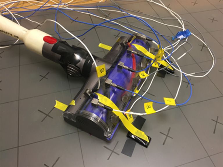
Applied Acoustics 182 (2021) 108144

                                                               Contents lists available at ScienceDirect

                                                                    Applied Acoustics
                                             journal homepage: www.elsevier.com/locate/apacoust

Vibro-acoustic analysis of a domestic product based on experimental
measurement and hybrid modelling
J.W.R Meggitt a, A. Clot b,d, G. Banwell c, A.S. Elliott a, A.T. Moorhouse a, R.S. Langley b
a
  Acoustics Research Centre, University of Salford, UK
b
  Department of Engineering, University of Cambridge, UK
c
  Dyson Technology LTD, Malmesbury, UK
d
  Acoustical and Mechanical Engineering Laboratory (LEAM), Universitat Politécnica de Catalunya (UPC), Spain

a r t i c l e        i n f o                           a b s t r a c t

Article history:                                       The purpose of this paper is to present a case study whereby a hybrid experimental–numerical model is
Received 23 November 2020                              used to analyse the structure-borne radiation from a domestic product (vacuum cleaner head). The pas-
Received in revised form 19 April 2021                 sive (including radiative) properties of the structure are modelled using the hybrid FE-SEA method. The
Accepted 22 April 2021
                                                       product’s operational activity, which lies beyond the capabilities of conventional modelling methods, is
Available online 1 June 2021
                                                       characterised experimentally using inverse force identification. The identified forces and passive model
                                                       are combined to form a so called hybrid FE-SEA-eXperimental model of the assembly. The FE-SEA-X
Keyword:
                                                       model is then used to identify dominant contributions from the assembly’s sub-components.
Hybrid modelling
FE-SEA
                                                       Ó 2021 The Authors. Published by Elsevier Ltd. This is an open access article under the CC BY license (http://
Experimental                                                                                                              creativecommons.org/licenses/by/4.0/).
Blocked forces
Domestic product

1. Introduction                                                                            design tool should incorporate both experimental and numerical
                                                                                           approaches, gaining from their respective advantages. In the pre-
    Domestic products such as vacuum cleaners, refrigerators, etc.                         sent paper we consider a case study whereby the combined appli-
are a major source of disturbance in the home. This is true to the                         cation of experimental and numerical methods (i.e. a hybrid
extent that manufactures are legally required to provide appli-                            model) are used to analyse the radiated sound pressure from a
ance noise ratings (sound power), and sales may be prohibited                              domestic product.
if set levels are exceeded [1]. Poor acoustic design may even go                               The appliance considered is a Dyson cordless vacuum cleaner
as far as causing reputation damage [2]. On the other hand, the                            (see Fig. 1a). In particular, we are interested in the sound radi-
rewards for good acoustic design are high, with increased sales                            ated from its cleaner head (see Fig. 1b). The cleaner head is a
and brand differentiation [2]. As such, it is no surprise that                             shell like structure with an integrated rotating brush bar which
vibro-acoustic attributes are afforded a very high priority in pro-                        is in contact with the floor. A (numerical) hybrid FE-SEA model
duct design.                                                                               is set up to describe the propagation and radiation, whilst
    Clearly, an appropriate understanding of a product’s vibro-                            experimental inverse force identification is used to obtain oper-
acoustic performance would benefit its manufacturer, enabling                              ational characteristics (which are too complex to model numer-
design modifications that reduce product sound level (or perhaps                           ically). These approaches are then combined to form a hybrid
improve sound quality) whilst retaining an expected performance.                           FE-SEA-X model [3], capable of predicting the radiated sound
This issue is often tackled through physical prototyping. This is not                      pressure from the cleaner head and the floor that it is in con-
only time consuming but expensive. For this reason computational                           tact with.
approaches are in favour. However, the complexities of a product’s                             Having outlined the context of this paper, its content will be
operation often render standard numerical methods (e.g. the finite                         organised as follows. Section 2 will begin by describing the prob-
element method) unsuitable. These operational features are, how-                           lem and detailing the modelling strategy adopted. Section 3 then
ever, amenable to experimental characterisation. Hence, a robust                           introduces the key methods used in this paper (including hybrid
                                                                                           FE-SEA, blocked forces and pseudo forces). The case study results
                                                                                           are then presented in Section 4. Finally, some concluding remarks
    E-mail address: j.w.r.meggitt1@salford.ac.uk (J.W.R Meggitt)                           are drawn in Section 5.

https://doi.org/10.1016/j.apacoust.2021.108144
0003-682X/Ó 2021 The Authors. Published by Elsevier Ltd.
This is an open access article under the CC BY license (http://creativecommons.org/licenses/by/4.0/).
J.W.R Meggitt, A. Clot, G. Banwell et al. Applied Acoustics 182 (2021) 108144
Fig. 3. Schematic of the hybrid FE-SEA-X model.
Fig. 1. Dyson vacuum cleaner.
cleaner head and floor sub-systems have a negligible influence
on one another. Hence, this interface is not considered in the cur-
rent hybrid model.
2. Problem description Owing to their high modal densities, the room and floor are rep-
resented by SEA sub-systems, whilst the cleaner head structure is
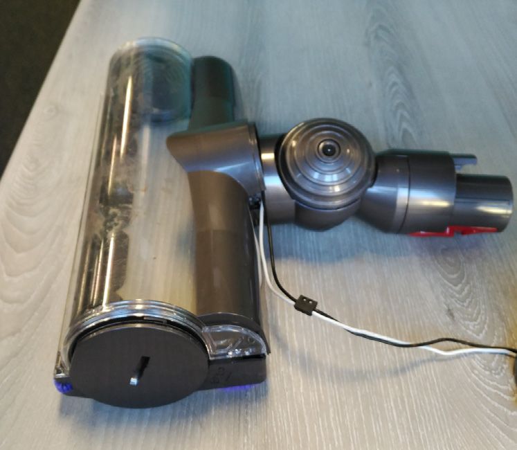
The cleaner head in question has an integrated brush-bar with modelled using a simplified finite element shell model.
carbon fibre and stiff nylon bristles that rotates at approx. 3600 The operation activity of the cleaner head can similarly be sub-
RPM. The stiff bristles agitate debris embedded into carpets while divided into two parts: the cleaner head (inc. brush bar)-floor
the carbon fibre filaments sweep up fine dust on hard-floor sur- interaction, and the brush bar-cleaner head interaction. The clea-
faces. Although previous work [4] indicates that the noise emitted ner head-floor interaction occurs at their separating interface,
by brush-bars of this type is predominantly driven by vibro- illustrated in Fig. 4a by a series of green markers. In the present
acoustic radiation from the housing of the assembly, it is thought paper this interaction will be represented by a series of experimen-
that on lightweight hard floors, the brush bar may be able to excite tal blocked/contact forces (see Section 3.2). The brush bar-cleaner
the floor which could then radiate acoustic energy to the far field head interaction occurs over a more complex interface within the
(see Fig. 2). To investigate this possibility, a hybrid FE-SEA-X model cleaner head structure. For experimental convenience a pseudo
has been used to determine vibro-acoustic contributions of the force-based approach will be adopted, where the underlying inter-
housing and floor to the total structurally radiated sound pressure face forces are instead represented by a series of external point-like
level. (pseudo) forces (see Section 3.3). These pseudo forces will be
determined using a mixed experimental/numerical method. Some
2.1. Modelling strategy preliminary external force locations considered are shown in
Fig. 4b and c by red markers.
The strategy adopted within this work was devised to further The operational (blocked/contact and pseudo) forces are deter-
understand the sources and transfer paths primarily responsible mined by inverse force identification methods, as detailed in Sec-
for emitting the sound associated with vacuum cleaner heads of tion 3.2 and 3.3, respectively. They will be used to excite the
this type. A schematic of the hybrid FE-SEA-X model considered hybrid FE-SEA-X model, as illustrated in Fig. 3 and shown in
here is shown in Fig. 3. The problem has been subdivided into 3 Section 4.
distinct domains, or sub-systems: the cleaner head/shell, the
floor/plate, and the surrounding room/cavity. These sub-systems 3. Methods
are separated by 3 interfaces (orange links in Fig. 3); the cleaner
head-room (structural–acoustic) interface, the cleaner head-floor This section will provide a brief summary of the methods used
(structural-structural) interface, and floor-room (structural–acous- to construct the hybrid FE-SEA-X model and characterise the struc-
tic) interface. Note that the cleaner head-floor interface, as repre- ture’s operational activity. Where necessary references will be
sented by the dashed link, provides only weak coupling; the given to more detailed articles on the respective methods.
Fig. 2. Diagram of the vibro-acoustic transfer paths considered.
2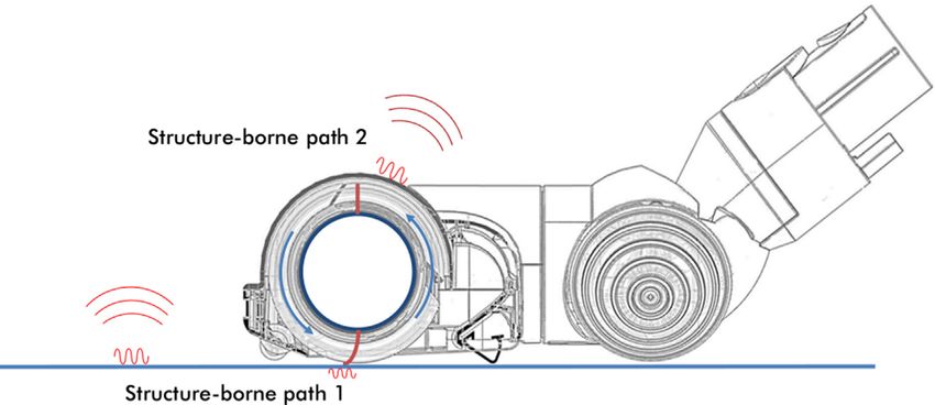
J.W.R Meggitt, A. Clot, G. Banwell et al.                                                                                              Applied Acoustics 182 (2021) 108144

                                            (a)

                                                                                                   Fig. 5. FE model representing the cleaner head’s outer shell.

                                                                                          fields: the response due to the initially generated waves (termed
                                                                                          the direct field), and the contribution from all waves reflected by
                      (b)                                  (c)
                                                                                          the sub-system boundaries (termed the reverberant field). These
Fig. 4. Location of forces used to represent cleaner head operation. a) Position of       boundaries are considered unknown, and so the reverberant field
blocked/contact forces at the cleaner head-floor interface. b/c) Positions of the         is considered random (in an ensemble sense). Based on this sepa-
external pseudo forces used to represent the brush bar-shell interaction.                 ration, a direct field dynamic stiffness matrix Ddir is defined for
                                                                                          each statistical sub-system. This is the dynamic stiffness of the
3.1. Hybrid FE-SEA-X model                                                                sub-system in the absence of any reflections, i.e. the infinite sub-
                                                                                          system response. Analytical solutions for Ddir are available for
    Finite Element (FE) and Statistical Energy Analysis (SEA) are                         many simple cases. For the floor/plate and room/cavity considered
suitable, respectively, for the analysis of long and short wavelength                     here, formulations of the direct field stiffness matrices are
(sub-) systems. However, the components that comprise complex                             described, respectively, in [3,12,13].
engineering structures often have widely varying characteristic                               The contribution of the kth statistical sub-system to the total
wavelengths. In this case neither FE nor SEA are appropriate to                           system response q is modelled by first adding its direct field
model the complete system.                                                                                       ðkÞ
                                                                                          dynamic stiffness Ddir to that of the deterministic stiffness matrix
    Based on a diffuse field reciprocity relation [5,6], a general
                                                                                          Dd (here representing the cleaner head structure), and then apply-
wave-based approach for coupling both theories into a single                                                                           ðkÞ
model has been proposed by Shorter and Langley [7]. Termed the                            ing an appropriate reverberant force f rev to the connecting degrees
‘hybrid FE-SEA’ method, this approach has since been validated                            of freedom (DoFs). This force describes the loading that arises due
both numerically and experimentally [8], and has proven itself as                         to the reverberant field in the statistical sub-system. For the vibro-
a valuable vibro-acoustic prediction tool. The method has been fur-                       acoustic system considered here, the governing equations of
ther extended to predict the variance of a response due to both                           motion are [7],
non-parametric (i.e. arising from SEA sub-systems) [9] and para-                                                        X
                                                                                                                        2
                                                                                                                            ðkÞ
metric (i.e. arising from FE components) [10,11] uncertainties.                           Dtot ðxÞqðxÞ ¼ f d ðxÞ þ        f rev ðxÞ                                   ð1Þ
The use of experimental data to represent complex sub-systems                                                            k¼1
that cannot be modelled directly was recently proposed in [3]. In
                                                                                          where f d represents an external forcing applied directly to the
the present paper we will apply this FE-SEA-X methodology to
                                                                                          deterministic part, and
the vibro-acoustic analysis of a domestic product, namely, a Dyson
cordless vacuum cleaner.                                                                                        X
                                                                                                                2
                                                                                          Dtot ðxÞ ¼ Dd ðxÞ þ     Ddir ðxÞ
                                                                                                                   ðkÞ
    The hybrid equations introduced below are done so in the con-                                                                                                     ð2Þ
                                                                                                                k¼1
text of the current case study. For a more general treatment of the
hybird FE-SEA(-X) method the reader is referred to [7,3].                                 is the total stiffness matrix. In Eq. (2), Dd represents the dynamic
    The hybrid FE-SEA method requires each component of the                               stiffness matrix of the deterministic cleaner head structure, whilst
vibro-acoustic system under study (see Section 2) to be identified                         ð1Þ      ð2Þ
                                                                                          Ddir and Ddir represent, respectively, the direct field stiffness matri-
as either deterministic or statistical. The deterministic part is rep-
                                                                                          ces of the statistical floor (plate) and room (cavity) sub-systems.
resented by a finite set of DoFs q, and the statistical part by a set of                                               ð1Þ      ð2Þ
sub-systems, each represented by a single DoF, their vibrational (or                      Similarly, in Eq. (1), f rev and f rev represent the reverberant forces
acoustical) energy E. As discussed in Section 2.1, in the present case                    applied to the cleaner head by, respectively, the floor and room
study the cleaner head structure is considered deterministic, owing                       sub-systems.
to its low modal density. In contrast, given their high modal densi-                          The hybrid FE-SEA-X methodology considers the case whereby
ties, the floor and room (plate and cavity) sub-systems are consid-                       certain components of a system cannot be modelled numerically,
ered statistical.                                                                         so are instead represented by experimental sub-systems. Gener-
    Treatment of the deterministic part follows standard Finite Ele-                      ally, in the presence of j experimental sub-systems the determinis-
ment procedure; the cleaner head is represented by the simplified                         tic dynamic stiffness matrix Dd is modified as so,
shell model shown in Fig. 5. Whilst simplified geometrically, it is
                                                                                                          X ðjÞ
                                                                                          Dd ¼ Dd;FE þ     Dd;exp                                                     ð3Þ
expected that this FE model will suitably describe the radiative                                           j
properties of the cleaner head.
                                                                                                                ðjÞ
    For the statistical sub-systems (i.e. the floor and room), we con-                    where Dd;FE and Dd;exp represent the dynamic stiffness matrices
sider the contained wave fields as combinations of two separate                           of the numerical part and the jth experimental sub-system,
                                                                                      3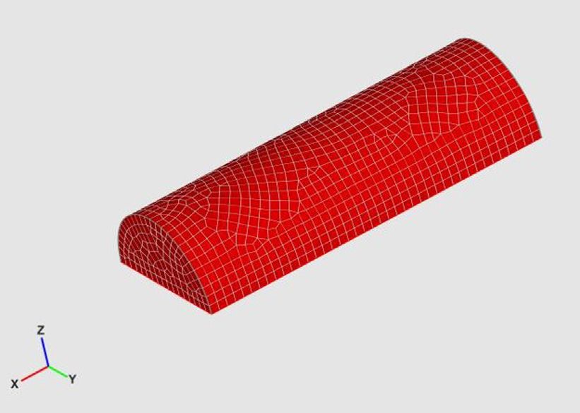
J.W.R Meggitt, A. Clot, G. Banwell et al.                                                                                                  Applied Acoustics 182 (2021) 108144

respectively. In the presence of j active experimental sub-systems                             Eqs. (6)–(8) form the basis of the hybrid FE-SEA-X model con-
(i.e. vibration sources) the deterministic force vector f d is also mod-                    sidered here. What is left to consider is the experimental determi-
ified as,                                                                                   nation of the cross-spectral force matrices Sext        exp
                                                                                                                                           ff and Sf f .
                   X
f d ¼ f ext þ       f ðjÞ                                                        ð4Þ          It is noted that for the present case study the hybrid equations
                       exp
                      j                                                                     presented above are solved using the commercial software wave6
                                                                                            [15], hence some more detailed aspects of the model’s construction
where f ext represents an external force applied directly to the                            are omitted.
numerical part, and f exp the blocked force of the jth experimental
                       ðjÞ

sub-system. If the jth experimental sub-system is purely passive,                           3.2. Inverse (blocked) force identification
then f ¼ 0.
       ðjÞ
           exp
      In the present case study the dynamic stiffness of the cleaner                           To include an experimental description of a vibration source
 head structure is modelled numerically, so no experimental stiff-                          within a hybrid FE-SEA-X model its operational activity must be
 ness matrices are required. As discussed in Section 2, the cleaner                         characterised independently, i.e. in such a way that it is invariant
 head’s operational activity is separated into two parts. The cleaner                       to the receiver structure. An appropriate characterisation can be
 head-floor interaction is characterised by a blocked/contact force                         achieved using the blocked force [16].
f ð1Þ (see Section 3.2) at the separating interface. The brush bar-                           With reference to Fig. 6, the blocked force describes the force
 exp
                                                                                            required to constrain the interface DoFs (c) of a vibration source
cleaner head interaction is instead represented by a set of external
                                                                                            such that their velocity (also displacement and acceleration) is
pseudo forces f ext (see Section 3.3) applied directly to the numerical
                                                                                            zero,
part.
    To obtain a hybrid FE-SEA(-X) model the above equations are                             f Sc ¼ f Cc j                                                                 ð9Þ
                                                                                                           vCc ¼0
not enough. The energetic properties of the statistical sub-
systems must be related to their reverberant forces and direct field                        where capitalised sub-scripts S and C denote the source and the
dynamic stiffness matrices. This is achieved by means of the diffuse                        coupled source-receiver assembly, respectively. The rigid constraint
field reciprocity relation [5], an identity that relates the cross-                         of the interface DoFs c removes the dynamic influence of the recei-
spectral matrix of a statistical sub-system’s reverberant force,                            ver structure, and so the blocked force is an independent property
 ðkÞ;rev             ðkÞ   ðkÞ T                                                           of the vibration source. As such, it remains a valid source character-
Sff        ¼ E½f rev f rev          , where E½     denotes the ensemble average, to
                                                                                            isation even if the receiver structure is modified or replaced.
                                                                    ðkÞ
its energy Ek and direct field dynamic stiffness Ddir . This relation-                          Direct measurement of the blocked force is complicated by the
ship, valid when the ensemble response constitutes a diffuse wave                           requirement of rigid constraints at the source interface. Fortu-
field [6], can be expressed as,                                                             nately, an indirect approach is available. It has been shown that
                                                                                            the blocked force can be obtained from in-situ measurements with
 ðkÞ;rev         4ak Ek              ðkÞ
Sff        ¼               ImfDdir g                                              ð5Þ       the source installed on an arbitrary receiver structure [16]. The
                 pxnk                                                                       equation of note is given by,
where Ek and nk are, respectively, the ensemble averaged vibra-
tional energy and modal density of sub-system k, and ak is a term
                                                                                            vCc ¼ YCccf Sc                                                              ð10Þ
that takes into account local concentrations in the wave field [14,9].                      where v Cc is an operational velocity measured at the interface DoFs
   Converting Eq. (1) into a quadratic form such that Sqq ¼ E½qqT ,                       c; YCcc is a mobility matrix measured at and between the interface
                                                                                            DoFs, and f Sc is the unknown blocked force (f
and substituting the diffuse field reciprocity relation, leads to,                                                                           ðjÞ
                                                                                                                                                 in Eq. (4)). The
                                                                                                                                                       exp
                 "                                      #
                            X
                            2
                              4ak Ek              ðkÞ
Sqq ¼ D1
       tot Sff þ                           ImfDdir g D1T                        ð6Þ
                             k¼1
                                    pxnk              tot

where, for the present case study, the cross-spectral force matrix is
given by,

Sff ¼ Sext    exp
       ff þ Sf f :                                                              ð7Þ

       In the above; Sqq represents the cross-spectral matrix of the sys-
tem response q; Sext      exp
                 ff and Sf f are the cross-spectral force matrices

corresponding to the brush bar-cleaner head pseudo force and
the cleaner head-floor blocked force, respectively, and E1 and E2
represent the vibrational and acoustical energy in the floor and
room sub-systems, respectively.
   To solve Eq. (6) the energy Ek of each sub-system must first be
determined. This is done by solving a power balance equation of
the form [7],
   ^ ¼ P þ Pext
C0 E                                                                              ð8Þ
            in

where E ^ is a vector of ensemble averaged modal energies such that
^
Ek ¼ Ek =nk ; P and Pext are vectors of input powers due to external
                                    in
forces, and C0 is a matrix of coupling loss factors. For further details
the reader is referred to [7]. Once computed, the sub-system ener-
gies can be related to spatially averaged variables, for example E2
can be used to compute the sound pressure level in the surrounding
acoustic space/room.                                                                            Fig. 6. Representation of a source-receiver (SR) assembly and blocked force.

                                                                                        4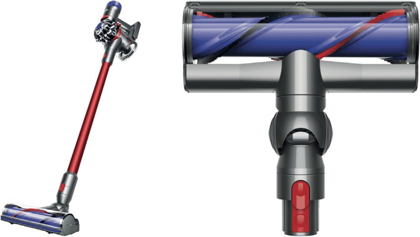
J.W.R Meggitt, A. Clot, G. Banwell et al.                                                                                             Applied Acoustics 182 (2021) 108144

blocked force is obtained by inversion of the measured mobility                            mobility matrix YRcc measured at the interface. Validation results
matrix,                                                                                    are presented in Section 4.1.1. The cross-spectral force matrix
f Sc ¼ Y1 v Cc :                                                                         Sexp
                                                                                             f f
                                                                                                  is then obtained by,
         Ccc                                                                  ð11Þ
   Once obtained, the blocked force can be used to predict the                             Sexp
                                                                                             f f
                                                                                                  ¼ f Sc f T
                                                                                                             Sc :                                                  ð14Þ
operational response at the remote receiver position b as per,
                                                                                              This cross-spectral force matrix will be used in the hybrid FE-
v Cb ¼ YCbc f Sc :                                                           ð12Þ         SEA-X model to represent the cleaner head-floor interaction.

    The in-situ blocked force characterisation requires a two part                         3.3. Pseudo forces
measurement procedure. In part one the source is turned off and
the mobility matrix YCcc is measured. Then, in part two, the source                           Often the interface between a source and receiver is unclear, or
is operated and the operation velocity v Cc is measured. For further                       perhaps inaccessible. In this situation, it is not straightforward to
details regarding practical considerations the reader is referred to                       obtain the (independent) blocked force as described above. An
[17,18].                                                                                   alternative approach is available however, given some limiting
    To correctly represent a vibration source within a hybrid FE-                          restrictions [19,20].
SEA-X model, it is important that the blocked force is accompanied                            Suppose some internal forces f So are developed within a vibra-
by a description of the passive source properties. This is achieved                        tion source. These forces will excite the source, which will in turn
                                                                               ðjÞ
as per Eq. (3), by adding its dynamic stiffness matrix DScc (Dd;exp                        excite the connected receiver through some set of interface DoFs c.
in Eq. (3)) to that of the numerical part. Experimentally, the                             The response at this interface is given by,
dynamic stiffness can be obtained by inversion of the free source
                                                                                           vCc ¼ YCco f So :                                                       ð15Þ
mobility, YScc , according to,
                                                                                              The internal forces are generally in accessible for characterisa-
DScc ¼ ixY1
          Scc :                                                               ð13Þ         tion. However, it is possible to define a new set of external pseudo
   Alternatively, it can be modelled numerically using standard FE                         forces f Ca that, in place of f So , generate an identical response field at
methods. In the present case study the blocked force approach is                           the interface c,
used to characterise operational activity at the cleaner head-floor                        vCc ¼ YCca f Ca ;                                                       ð16Þ
interface, as described in Section 2. Following a preliminary test it
was observed that, due to weak coupling between the floor and clea-                        and hence in the receiver structure also,
ner head, the coupled mobility YCcc was approximately equal to                             vCb ¼ YCba f Ca :                                                       ð17Þ
uncoupled floor (receiver) mobility YRcc (see Fig. 7). Importantly, this
weak coupling introduces an equivalence between the blocked force                             An exact reproduction of v Cc (and v Cb ) would require the num-
and contact force. Furthermore, it suggests that the floor and cleaner                     ber of external forces (i.e. DoFs a) to be equal to the number of
head can be treated independently, i.e. their coupling can be                              interface DoFs c. The position of these new pseudo forces are arbi-
neglected in the hybrid model. Hence, the cleaner head and floor                           trary (they can be chosen for convenience), provided that they
sub-system in Fig. 3 are not connected. This is of course unique to                        excite a sufficient number of modes. Hence, they provide a conve-
the present case study, and in a more general FE-SEA-X model cou-                          nient alternative to the in-situ blocked force method when the
pling between all sub-systems should be considered.                                        interface is inaccessible.
   For experimental convenience, the receiver mobility is used in                             The pseudo forces f Ca are obtained by inversion of the measured
place of the coupled mobility to characterise the cleaner head-                            mobility matrix YCca (or YCba ), as per a standard inverse force
floor interaction. Hence, the forces determined, strictly speaking,                        identification,

                                                                                                   Cca v Cc ¼ YCba v Cb :
are contact forces. Nevertheless, given their equivalence to the                           f Ca ¼ Y1          1
                                                                                                                                                                   ð18Þ
blocked force in the presence of weak coupling, the term blocked
force will continue to be used.                                                               Whilst the pseudo forces will reproduce the interface and recei-
   Upon discretising the cleaner head-floor interface (see Fig. 4a) a                      ver response fields, they are not unique. Different pseudo force
set of 9 blocked forces are determined by inverting the 9  9                              positions will yield different pseudo forces. Nor are they transfer-
                                                                                           able between assemblies (like the blocked force). Nevertheless,
                                                                                           they will reproduce the velocity field across a receiver structure,
                                                                                           providing they are sufficient in number.
                                                                                              In the present case study the pseudo force method is used to
                                                                                           characterise the excitation of the cleaner head’s shell-like structure
                                                                                           by the operating brush bar. The brush bar-cleaner head interface is
                                                                                           complex and hard to define, hence the use of the pseudo force.
                                                                                           Given their arbitrary positioning, different sets of excitation DoFs
                                                                                           can be considered. As part of a preliminary experimental study
                                                                                           two sets of pseudo force locations are considered. These are shown
                                                                                           in Fig. 4b and c by red markers, with results presented in
                                                                                           Section 4.1.2.
                                                                                              Whilst pseudo forces are typically obtained by experimental
                                                                                           means, where both the operational response and mobility matrix
                                                                                           are measured, the pseudo forces used to excite the hybrid model
                                                                                           considered here are instead determined using a combined experi-
                                                                                           mental/numerical approach. Experimental response measure-
Fig. 7. An example interface point mobility with (blue, YCcc ) and without (orange,
                                                                                           ments are combined with a numerical mobility matrix obtained
YRcc ) the cleaner head present. Their similarity demonstrates a) the equivalence of
the contact force and blocked force and b) the lack of direct coupling between             from the FE shell model representing the cleaner head. The
cleaner head and floor sub-systems.                                                        cross-spectral force matrix Sext
                                                                                                                         ff is then obtained by,

                                                                                       5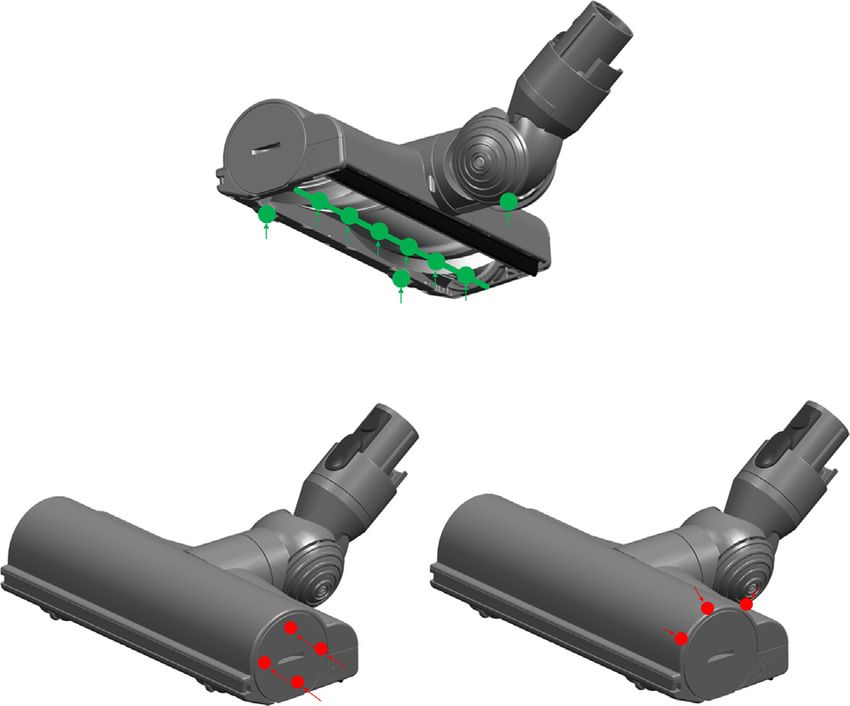
J.W.R Meggitt, A. Clot, G. Banwell et al.                                                                                     Applied Acoustics 182 (2021) 108144

             T
Sext
 ff ¼ f Ca f Ca :                                                ð19Þ

   This cross-spectral force matrix will be used in the hybrid FE-
SEA-X model to represent the brush bar-cleaner head interaction.

4. Results

4.1. Experimental

    In this section we will describe in greater detail the experimen-
tal procedures employed to characterise and validate the opera-
tional activity of the cleaner head assembly. We will further
consider, by experimental means, the radiated structure-borne
sound contributions from the floor (represented here by a plate)
and cleaner-head shell components. This result will serve as a com-
parison for the hybrid FE-SEA-X model to be introduced shortly.
    Elements of the procedures presented below will be used in
Section 4.2 to provide excitation of the hybrid FE-SEA-X model
(see Fig. 3). In summary, the SEA floor sub-system will be excited
by the blocked forces described in Section 4.1.1. The cleaner head
shell will be excited by the set of hybrid experimental/numerical
pseudo forces described in Section 4.2.2. Prior to this the pseudo
force methodology will be validated experimentally in
Section 4.1.2.

4.1.1. Floor response prediction
    To predict the radiated sound pressure from the floor due to the
operational cleaner head, the forces acting at their separating
interface must be determined. These forces, when combined with
appropriate vibro-acoustic transfer functions, should provide an
estimate of the radiated sound pressure due to the interface forces
acting on the floor only, i.e. neglecting radiation from the cleaner         Fig. 8. Experimental set-up for validation of blocked/contact force characterisation.
head’s shell structure.                                                      Green crosses - interface DoFs c, yellow crosses – reference receiver DoFs b. (For
    As is often the case in practical scenarios, the interface between       interpretation of the references to color in this figure legend, the reader is referred
                                                                             to the web version of this article.)
the floor and vacuum head is somewhat unclear. Three point like
DoFs were identified as the two small front wheels and a rear ball
pivot (see Figs. 2 and 4a). The remaining interface is that between
the rotating brush bar and the floor. In reality, this may be viewed         operational response at the two reference positions away from the
as a moving interface; the brush bar bristles are only ever in con-          interface (see Fig. 8) as per Eq. (12).
tact with the floor at two positions as it rotates. To simplify the             For comparison purposes, these reference responses were also
experimental procedure the interface has instead been defined as             measured directly. The on-board validation results are shown in
a series of point-like DoFs (so as to approximate a line junction).          Fig. 9. The predicted velocity response (orange) is in good agree-
Given the rotational speed of the brush bar, all DoFs will experi-           ment with the directly measured response (blue) in both cases.
ence repeated excitation through a single FFT window. Shown in               This result suggests that the interface description used is appropri-
Figs. 4a and 8a are the chosen interface DoFs.                               ate and that the contact forces able to sufficiently characterise the
    Given the weak coupling between the cleaner head and floor, it           cleaner head-floor interaction.
was noted that the presence of the cleaner head had little to no                Having characterised the forces imparted on the floor by the
effect on the dynamics of the interface (i.e. the coupled and uncou-         operational cleaner head, it is possible to perform a contribution
pled mobilities are approximately the same YCcc  YRcc ) above               analysis (also known as Transfer Path Analysis) to investigate the
100 Hz. This result is illustrated in Fig. 7, where the point mobility       dominance of a particular set of DoFs. An example of this is shown
at one interface DoF is shown for the coupled (blue, cleaner head-           in Fig. 10 where the contributions arising from the brush bar, the
floor) and uncoupled (orange, floor only) case. It is clear that from        front wheels, and the rear pivot are separated and compared
approximately 100 Hz the two are in very close agreement. A sim-             against one another. These results indicate that at low frequencies
ilar result was obtained for all remaining interface mobilities.             (below 100 Hz) all DoFs tend to contribute equally, in the mid fre-
Based on this result we may justly use the interface contact force           quency range (between 100 and 1500 Hz) the front wheels tend to
in place of the blocked force.                                               dominate, and at high frequencies (above 1500 Hz) the brush bar
    Shown in Fig. 11a is the experimental set-up used. The cleaner           tends to dominate. This sort of information may prove useful, for
head was placed on a perspex plate (representing the floor), to              example in assessing design changes.
which 11 accelerometers were stuck; 9 at the separating interface               Based on the above results it is deemed that the interface
c, and 2 at remote positions b. The 9  9 interface mobility matrix          description adopted is suitable for characterising the cleaner
YRcc  YCcc was measured using an instrumented force hammer,                 head-floor interaction, and furthermore that the cleaner head
after which the operational response v Cc was recorded. The forces           dynamics may be neglected when considering the floor
were then determined as per Eq. (11).                                        contribution.
    Before considering the radiated sound pressure, the interface               In Section 4.1.3 the above procedure is repeated whilst the clea-
description described above was validated using an on-board vali-            ner head-floor assembly is installed in a semi-anechoic chamber.
dation procedure [21]. The obtained forces were used to predict the          This will enable the prediction of radiated sound pressure by
                                                                         6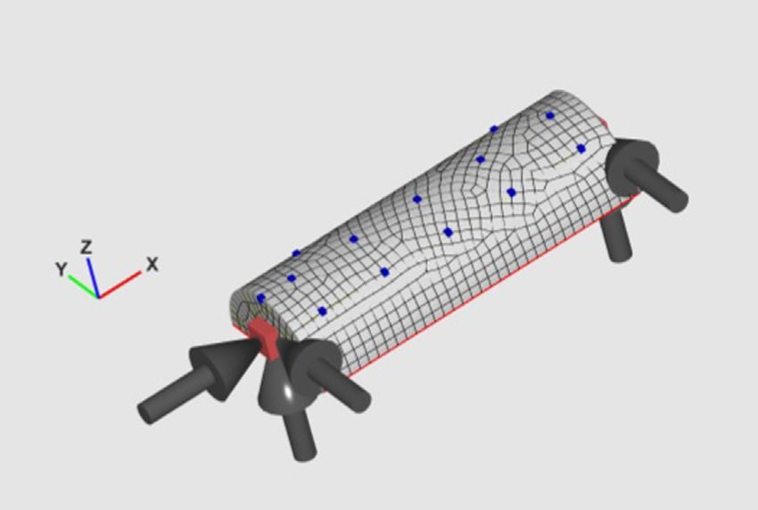
J.W.R Meggitt, A. Clot, G. Banwell et al.                                                                                                 Applied Acoustics 182 (2021) 108144

                                                                                               Fig. 11. Experimental set-up for the validation of the pseudo-force method.

                                                                                            ver structure. An important feature of the pseudo force approach is
                                                                                            the arbitrary nature of their positioning. We are interested in
                                                                                            adopting the pseudo force approach to characterise the mecha-
                                                                                            nisms that cause the cleaner head shell to vibrate, and conse-
Fig. 9. On-board validation of the preliminary floor study. The acquired forces are         quently radiate sound. To validate the pseudo force method, in
used to predict the operational response v Cb at two different reference receiver           this section we consider an entirely experimental application,
positions.
                                                                                            where both mobilities and operational responses are measured.
                                                                                            The pseudo forces used within the hybrid FE-SEA-X model in Sec-
                                                                                            tion 4.2, however, are determined by using transfer mobilities
measuring the vibro-acoustic FRFs from the interface DoFs to a                              obtained from a FE shell model, as described in Section 4.2.2.
microphone hemi-sphere. In Section 4.2.1 the obtained forces will                              Shown in Fig. 8 is the experimental set-up used. The cleaner
be used to excite the floor sub-system of the hybrid FE-SEA-X                               head shell was instrumented with 12 response sensors (accelerom-
model of the assembly.                                                                      eters). Based on the operational responses measured at these posi-
                                                                                            tions, two different sets of pseudo forces are determined. The
                                                                                            number, and position, of these pseudo forces are shown in
4.1.2. Shell response prediction
                                                                                            Figs. 4b and c. Two sets of pseudo forces were considered given
    In Section 4.1.1 we considered the cleaner head-floor interface.
                                                                                            that the brush bar-shell interface is somewhat unclear. The pseudo
In this section we will consider the brush bar-cleaner head (shell)
                                                                                            forces were obtained by first measuring the operational shell
interface, with the intention of predicting its radiated sound pres-
                                                                                            response at each sensor position. Then the transfer mobilities
sure contribution. The approach adopted here will be that of the
                                                                                            between each force position and sensor were measured. The
pseudo force described in Section 3.3.
                                                                                            pseudo forces were then obtained as per Eq. (18). Note that when
    As discussed in Section 3.3, pseudo forces are external forces
                                                                                            calculating the pseudo forces only 11 response measurements are
which, when applied, recreate an identical response field in a recei-
                                                                                            used. The 12th is retained as a reference point for an on-board
                                                                                            validation.
                                                                                               Shown in Fig. 12 are the on-board validation results for the two
                                                                                            sets of pseudo forces. Good agreement is obtained in both cases up
                                                                                            to 1 kHz, beyond which the two predictions begin to deviate from

Fig. 10. Contribution analysis of the operational response v Cb due to the brush bar,       Fig. 12. On-board validation of pseudo forces. The determined pseudo forces are
front wheels and pivot. Upper – narrow band; lower – third octave bands.                    used to predict the operational response v Cb at a remote position on the shell.

                                                                                        7
J.W.R Meggitt, A. Clot, G. Banwell et al.                                                                                                      Applied Acoustics 182 (2021) 108144

the measure response. Nevertheless, the general shape of                           the
response is still predicted quite well. The results suggest that                   the
pseudo forces method is appropriate and able to reproduce                          the
response of the cleaner head shell when subject to the brush                       bar
excitation.

4.1.3. Vibro-acoustic contributions
   Sections 4.1.1 and 4.1.2 focused on predicting the structural
response of the floor and cleaner head, respectively, based on the
obtained blocked/contact and pseudo forces. In this section we will
consider the contribution of these forces to the total radiated
sound.
   To predict the radiated sound pressure the blocked/contact and
pseudo forces are combined with measured vibro-acoustic FRFs.
These FRFs were measured in a semi-anechoic chamber by apply-
ing a known force to each interface DoF/pseudo force location, and                             Fig. 14. Comparison of the floor/plate (blue) and shell (orange) contributions to the
measuring the resultant pressure level over a hemi-spherical                                   spatially averaged radiated sound pressure level. Also shown is the total measured
                                                                                               pressure level (black). (For interpretation of the references to color in this figure
microphone array surrounding the cleaner head-floor assembly.                                  legend, the reader is referred to the web version of this article.)
   Shown in Fig. 13 are the (spatially) averaged FRFs from each
excitation position to a single microphone. Shown in bold is an
averaged FRF across all excitation and response positions. Based                               4.2. Hybrid FE-SEA-X model
on these FRFs the averaged sound pressure contributions of the
floor and cleaner head are shown in Fig. 14, alongside the total                                   In this section, we will develop a hyrbid FE-SEA-X model to rep-
measured response.                                                                             resent the vibro-acoustic behaviour of the vacuum cleaner operat-
   It should be noted only structure-borne contributions are con-                              ing within a room. As for the experimental procedures presented in
sidered here; any air-borne contribution, say due to brush bar-                                Section 4.1, the aim is to use this model to compare the radiated
plate interaction, is neglected. Hence, the predictions are simply                             structure-borne sound contributions from the cleaner head and
intended to provide an indication of the relative contribution of                              floor. In brief, the hybrid model considers the outer shell of the
the cleaner head and floor vibration to the total radiated sound                               cleaner head as the deterministic part of the system, represented
pressure level.                                                                                by an FE model, and both the room volume and the floor as statis-
   From Fig. 14 it is clear that the relative contribution of floor and                        tical sub-systems. As discussed in the following subsections, the
cleaner head varies considerably with frequency. At low frequen-                               operational activity of the cleaner head is characterised using the
cies, below approximately 300 Hz their contributions are similar.                              experimental data obtained through Section 4.1.
Above 300 Hz the cleaner head radiation tends to dominate. The                                     A schematic of the hybrid model is presented in Fig. 3. The
general trend of this result appears in agreement with previous                                experimental blocked/contact forces characterising the brush-
studies on a similar brush bar assembly [4]. Furthermore, as                                   bar-floor interaction are input to a 2D SEA plate sub-system, itself
expected, there appears to be a general under prediction in the                                coupled to a 3D SEA cavity sub-system representing the enclosed
mid to high frequency range. This is most likely due to air-borne                              room. A set of experimental/numerical pseudo forces (see Sec-
contributions that are not accounted for by the structural methods                             tion 4.2.2), representing the brush bar-shell interaction, are used
employed here. Nevertheless, the result appear sensible.                                       to excite the FE model. This FE model is then coupled to the same
   In the following section a similar prediction will be made,                                 3D SEA sub-system. The model has been implemented in the com-
instead using a hybrid FE-SEA-X model of the assembly, supple-                                 mercial vibro-acoustic software wave6 [15].
mented with the experimental data presented in this section.                                       The room sub-system is given dimensions 3.5 m  4.5 m  3 m,
                                                                                               with a floor surface area of 15.75 m2 and a room volume of 42 m3.
                                                                                               The floor sub-system is specified as concrete with a thickness of
                                                                                               6 cm. The noise radiated into the room up to 2000 Hz will be con-
                                                                                               sidered in the calculations. In the frequency range of interest the
                                                                                               floor sub-system has around 300 structural modes, while more
                                                                                               than 30000 modes are expected in the room sub-system. Hence,
                                                                                               an SEA representation is considered appropriate.

                                                                                               4.2.1. Floor response prediction
                                                                                                  The developed hybrid FE-SEA-X model assumes that the floor
                                                                                               and the room can be considered as statistical sub-systems. This
                                                                                               assumption is supported by the large number of modes estimated
                                                                                               in each sub-system. On the other hand, the cleaner head geometry
                                                                                               and material properties suggest that it should be modelled as a
                                                                                               deterministic structure, a suggestion that will be supported in
                                                                                               the next subsection.
                                                                                                  The results presented in Section 4.1.1 showed that, due to the
                                                                                               weak coupling between the cleaner head and the floor, the
                                                                                               obtained blocked forces are approximately equal to the interface
Fig. 13. Vibro-acoustic transfer function from the shell pseudo-force positions (red)
and cleaner head-floor interface DoF (blue) to microphone hemi-sphere. Bold plot
                                                                                               contact forces. Therefore, the floor contribution to the radiated
shows the spatial average. (For interpretation of the references to color in this figure       structure-borne sound can be computed without having to con-
legend, the reader is referred to the web version of this article.)                            sider the cleaner head. This result is particularly advantageous
                                                                                           8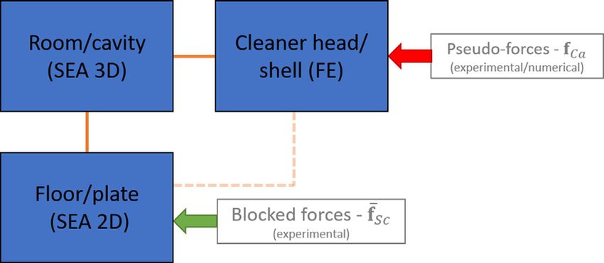
J.W.R Meggitt, A. Clot, G. Banwell et al.                                                                                    Applied Acoustics 182 (2021) 108144

here, as it states that there is no need to explicitly couple a detailed
FE model of the cleaner head to that of the SEA floor sub-system.
Their contributions may be treated separately. Then, as indicated
in Fig. 3, the floor contribution to the room response is directly
computed by inserting the experimental blocked/contact forces
as point forces applied on the SEA floor sub-system.

4.2.2. Shell response prediction
    The approach used for predicting the shell contribution to the
radiated structure-borne sound resembles the pseudo-force
approach presented in Section 4.1.2. In this case, however, the
aim is to reproduce the operational response of the cleaner head
using a simplified FE model that only considers its outer shell, thus
overcoming the challenge of modelling the cleaner head structure
in detail.                                                                        Fig. 16. Pseudo-forces and response positions considered in the FE model.
    The proposed approach assumes that, when operating, the clea-
ner head’s outer shell is mainly excited by forces transmitted
through both shell ends (see Fig. 15). The outer shell is then mod-                Shown in Fig. 17 are the on-board validation results at two ref-
elled as a simplified FE structure excited by a discrete set of point          erence positions for the hybrid pseudo forces; measured responses
loads applied on its ends. The complex amplitudes of the point                 are compared against those predicted using the FE mobility matrix
loads can be determined by imposing that the FE model response                 and the hybrid experimental–numerical pseudo forces. Good
to these excitations is equal to the response measured experimen-              agreement is obtained up to around 1500 Hz, after which the com-
tally, as discussed in Section 3.3. The above amounts to determin-             puted response seems to over-predict the measured one. There-
ing a set of ‘hybrid’ pseudo forces based on experimental response             fore, it can be stated that the outer shell response under
measurements, and FE mobilities. It is proposed that these hybrid              operational conditions can satisfactorily be represented using the
pseudo forces, when applied to the simplified FE model, will pro-              considered set of pseudo forces for most of the frequency range
vide a reasonable approximation of the structural radiation. The               of interest.
FE model of the cleaner head’s shell structure has been developed                  As indicated in Fig. 3, the cleaner head’s shell contribution to
using wave6 software [15]. The shell has been assumed to be made               the radiated response is computed by applying the obtained
of perspex, with a constant loss factor g ¼ 0:06. The FE model,                pseudo forces to the FE shell component of the complete FE-SEA-
shown in Fig. 5, consists of 1293 2D shell elements. The model pre-            X model of the cleaner head-floor-room system.
dicted that the outer shell component has 42 modes up to 2000 Hz,
supporting the assumption that it is best represented as a deter-              4.2.3. Vibro-acoustic contributions
ministic system.                                                                   A comparison between the radiated structure-borne sound con-
    As in the experimental case, the pseudo forces f Ca are obtained           tributions is finally obtained by embedding the experimental
using Eq. (18), where v Cb are the measured operational shell                  blocked/contact forces acting on the floor, and the pseudo forces
responses. In this case, however, the structure mobility YCba has              applied on the cleaner head shell, in the hybrid FE-SEA-X model.
been computed using the shell FE model, instead of being deter-                To take into account the absorption and transmission of energy
mined experimentally. The pseudo force approach has been                       through the room walls and ceiling (which have not been included
applied considering three point forces at each end of the cleaner
head. The mobility matrix YCba was obtained by computing the
response to each one of these six excitations at the 12 receiver
points representing the measured response positions. These posi-
tions have been marked as blue dots in Fig. 16.
    As in the experimental case, the pseudo forces are determined
using only a subset of the total number of response positions;
the remaining positions are used for validation purposes.

                                                                               Fig. 17. On-board validation of the hybrid pseudo-forces obtained using experi-
                                                                               mental response data and the shell FE model. Two different reference positions are
            Fig. 15. Picture of the cleaner head outer shell component.        considered.

                                                                           9
J.W.R Meggitt, A. Clot, G. Banwell et al. Applied Acoustics 182 (2021) 108144
ner assembly. The in-situ blocked force approach was used to
characterise the activity of the cleaner head-floor interface. The
experimental blocked force data was then used to excite an SEA
sub-system, representing the floor, as part of a hybrid FE-SEA-X
model. To account for the radiated contribution of the cleaner
head, a set of pseudo forces were determined by combining exper-
imental response measurements with a numerical mobility matrix.
The ‘hybrid’ pseudo forces were used to excite a simplified FE
model of the cleaner head. Using the hybrid FE-SEA-X model, the
relative contributions of the SEA floor sub-system and the FE clea-
ner head, to the level in an enclosing room, were predicted. Com-
parison against a similar, but experimental, contribution analysis
showed the same general trends.
Whilst the case study was not aimed at providing a one-to-one
comparison between model and experiment, the results obtained
are supportive of the hybrid FE-SEA-X approach to modelling com-
plex operational structures.
CRediT authorship contribution statement
J.W.R Meggitt: Conceptualization, Methodology, Validation,
Fig. 18. Comparison between the radiated structure-borne sound contributions Investigation, Writing - original draft, Writing - review & editing.
form the floor and from the cleaner-head shell components. Results are presented A. Clot: Conceptualization, Methodology, Validation, Investigation,
in narrow band (top) and in one-third octave bands (bottom). Writing - original draft, Writing - review & editing. G. Banwell:
Conceptualization, Methodology, Validation, Investigation, Writing
- original draft, Writing - review & editing. A.S. Elliott: Conceptu-
as sub-systems in the model) a room damping of 1% has been con-
alization, Methodology, Validation, Investigation. A.T. Moorhouse:
sidered in the calculations. It should be noted, however, that the
Supervision, Funding acquisition. R.S. Langley: Supervision, Fund-
aim of the calculation is not to compare absolute sound pressure
ing acquisition.
values, but to compare relative contributions.
Shown in Fig. 18 are the relative contributions of the floor and
cleaner head, as predicted by the hybrid FE-SEA-X model. The Declaration of Competing Interest
numerical prediction appears in good agreement with the experi-
mental results shown in Fig. 14, following the same general trend. The authors declare that they have no known competing finan-
Both experimental and hybrid predictions indicate that the cleaner cial interests or personal relationships that could have appeared
head tends to contribute more towards radiated sound than the to influence the work reported in this paper.
floor, particularly at higher frequencies. This result supports previ-
ous studies on similar brush bar assemblies [4]. Acknowledgements
The hybrid floor contribution is only greater than the cleaner
head around the fundamental peak of 60 Hz, i.e. the operational This work was funded through the EPSRC Research Grant EP/
frequency of the brush bar. A similar result was obtained experi- P005489/1 Design by Science.
mentally in Fig. 14. It should be noted that, despite its apparent
importance, this peak would be strongly reduced if an A-
References
weighting were used, reducing its overall contribution. Agreement
between the general trends of the experimental results and the [1] Commission European. Commission Regulation (EU) No 666/2013 of 8th July -
hybrid model predictions are promising, and certainly supportive Implementing Directive 2009/125/EC of the European Parliament and of the
of hybrid FE-SEA-X approach to modelling complex operational Council with regard to ecodesign requirements for vacuum cleaners. Offic J Eur
Union 2013;285(24):24–34.
structures. [2] Martin RL. The design of business: Why design thinking is the next competitive
advantage. Harvard Business Press; 2009.
[3] Clot A, Meggitt JWR, Langley RS, Elliott AS, Moorhouse AT. Development of a
5. Conclusions hybrid FE-SEA-experimental model. J Sound Vib 2019;452:112–31.
[4] Taylor DM. Assessing the vibro-acoustic radiation characteristics of a compact
consumer appliance. In: Inter-noise and noise-con congress and conference
The purpose of this paper was to present a case study whereby a proceedings, vol. 253. Institute of Noise Control Engineering; 2016. p.
hybrid experimental–numerical model is used to analyse the 7430–40.
[5] Shorter PJ, Langley RS. On the reciprocity relationship between direct field
vibro-acoustic performance of a domestic product. It was argued radiation and diffuse reverberant loading. J Acoust Soc Am 2005;117(1):85.
that whilst conventional numerical methods are able to predict [6] Langley RS. On the diffuse field reciprocity relationship and vibrational energy
the propagative and radiative properties of a sub-structure or variance in a random subsystem at high frequencies. J Acoust Soc Am
2007;121(2):913–21.
assembly, the complex mechanisms that generate vibration lay [7] Shorter PJ, Langley RS. Vibro-acoustic analysis of complex systems. J Sound Vib
beyond their capabilities. These operational features are however, 2005;288(3):669–99.
amenable to experimental characterisation. By combining the in- [8] Cotoni V, Shorter PJ, Langley RS. Numerical and experimental validation of a
hybrid finite element-statistical energy analysis method. J Acoust Soc Am
situ blocked force approach for source characterisation, with the
2007;122(1):259–70.
established FE-SEA method for propagation and radiation, complex [9] Langley RS, Cotoni V. Response variance prediction for uncertain vibro-
operational structures can be modelled by exploiting their respec- acoustic systems using a hybrid deterministic-statistical method. J Acoust Soc
tive advantages. Am 2007;122(6):3445–63.
[10] Cicirello A, Langley RS. The vibro-acoustic analysis of built-up systems using a
The hybrid FE-SEA-X methodology was adopted here to investi- hybrid method with parametric and non-parametric uncertainties. J Sound Vib
gate relative vibro-acoustic contributions for a floor/vacuum clea- 2013;332(9):2165–78.
10J.W.R Meggitt, A. Clot, G. Banwell et al. Applied Acoustics 182 (2021) 108144
[11] Cicirello A, Langley RS. Efficient parametric uncertainty analysis within the [17] Elliott AS, Meggitt JWR, Moorhouse AT. Blocked forces for the characterisation
hybrid finite element/statistical energy analysis method. J Sound Vib 2014;333 of structure borne noise. In: Internoise 2015. San: Fransisco; 2015. p.
(6):1698–717. 5798–805.
[12] Langley RS. Numerical evaluation of the acoustic radiation from planar [18] Meggitt J.W.R., Moorhouse A.T., Elliott A.S. On the problem of describing the
structures with general baffle conditions using wavelets. J Acoust Soc Am coupling interface between sub-structures: an experimental test for
2007;121(2):766–77. ‘completeness’. In: IMAC XVIII, Orlando; 2018, p. 1–11..
[13] Langley RS, Cordioli JA. Hybrid deterministic-statistical analysis of vibro- [19] Janssens MHA, Verheij JW. A pseudo-forces methodology to be used in
acoustic systems with domain couplings on statistical components. J Sound characterization of structure-borne sound sources. Appl Acoust 2000;61
Vib 2009;321(3–5):893–912. (3):285–308.
[14] Langley RS, Cotoni V. The ensemble statistics of the vibrational energy density [20] Janssens MHA, Verheij JW, Loyau T. Experimental example of the pseudo-
of a random system subjected to single point harmonic excitation. J Acoust Soc forces method used in characterisation of a structure-borne sound source.
Am 2005;118(5):3064–76. Appl Acoust 2002;63(1):9–34.
[15] wave6. wave six llc. http://wavesix.com.. [21] International Organization for Standardization. Acoustics – Characterization of
[16] Moorhouse AT, Elliott AS, Evans TA. In situ measurement of the blocked force Sources of Structure-Borne Sound and Vibration – Indirect Measurement of
of structure-borne sound sources. J Sound Vib 2009;325(4–5):679–85. Blocked Forces ISO/DIS 20270:2018(E); 2018..
11You can also read