Red Hat Enterprise Linux 7 Load Balancer Administration - Load Balancer Add-on for Red Hat Enterprise Linux
←
→
Page content transcription
If your browser does not render page correctly, please read the page content below
Red Hat Enterprise Linux 7
Load Balancer Administration

Load Balancer Add-on for Red Hat Enterprise Linux
Red Hat Enterprise Linux 7 Load Balancer Administration

Load Balancer Add-on for Red Hat Enterprise Linux
Legal Notice
Co pyright © 20 15 Red Hat, Inc. and o thers.

This do cument is licensed by Red Hat under the Creative Co mmo ns Attributio n-ShareAlike 3.0
Unpo rted License. If yo u distribute this do cument, o r a mo dified versio n o f it, yo u must pro vide
attributio n to Red Hat, Inc. and pro vide a link to the o riginal. If the do cument is mo dified, all Red
Hat trademarks must be remo ved.

Red Hat, as the licenso r o f this do cument, waives the right to enfo rce, and agrees no t to assert,
Sectio n 4 d o f CC-BY-SA to the fullest extent permitted by applicable law.

Red Hat, Red Hat Enterprise Linux, the Shado wman lo go , JBo ss, MetaMatrix, Fedo ra, the Infinity
Lo go , and RHCE are trademarks o f Red Hat, Inc., registered in the United States and o ther
co untries.

Linux ® is the registered trademark o f Linus To rvalds in the United States and o ther co untries.

Java ® is a registered trademark o f Oracle and/o r its affiliates.

XFS ® is a trademark o f Silico n Graphics Internatio nal Co rp. o r its subsidiaries in the United
States and/o r o ther co untries.

MySQL ® is a registered trademark o f MySQL AB in the United States, the Euro pean Unio n and
o ther co untries.

No de.js ® is an o fficial trademark o f Jo yent. Red Hat So ftware Co llectio ns is no t fo rmally
related to o r endo rsed by the o fficial Jo yent No de.js o pen so urce o r co mmercial pro ject.

The OpenStack ® Wo rd Mark and OpenStack Lo go are either registered trademarks/service
marks o r trademarks/service marks o f the OpenStack Fo undatio n, in the United States and o ther
co untries and are used with the OpenStack Fo undatio n's permissio n. We are no t affiliated with,
endo rsed o r spo nso red by the OpenStack Fo undatio n, o r the OpenStack co mmunity.

All o ther trademarks are the pro perty o f their respective o wners.

Abstract
Building a Lo ad Balancer Add-On system o ffers a highly available and scalable so lutio n fo r
pro ductio n services using specialized Linux Virtual Servers (LVS) fo r ro uting and lo ad-
balancing techniques co nfigured thro ugh Keepalived and HAPro xy. This bo o k discusses the
co nfiguratio n o f high-perfo rmance systems and services using the Lo ad Balancer techno lo gies
in Red Hat Enterprise Linux 7.
T able of Cont ent s
T able of Contents
C
. .hapt
. . . .er
. .1. .. Load
. . . . .Balancer
. . . . . . . .O
. .verview
. . . . . . . . . . . . . . . . . . . . . . . . . . . . . . . . . . . . . . . . . . . . . . . . . . . . . . . . . . . . 2. . . . . . . . . .
1.1. keep alived 2
1.2. hap ro xy 2
1.3. keep alived and hap ro xy 2
C
. .hapt . . . .er
. .2. .. Keepalived
. . . . . . . . . .O
. .verview
. . . . . . . . . . . . . . . . . . . . . . . . . . . . . . . . . . . . . . . . . . . . . . . . . . . . . . . . . . . . . . . 4. . . . . . . . . .
2 .1. A Bas ic Keep alived Lo ad Balanc er Co nfig uratio n 4
2 .2. A Three-Tier keep alived Lo ad Balanc er Co nfig uratio n 6
2 .3. keep alived Sc hed uling O verview 7
2 .4. Ro uting Metho d s 10
2 .5. Pers is tenc e and Firewall Marks with Keep alived 12
C
. .hapt
. . . .er
. .3.
. .Set
. . .t.ing
. . . Up
. . . Load
. . . . .Balancer
. . . . . . . . Prerequisit
. . . . . . . . . .es
. . for
. . . Keepalived
. . . . . . . . . . . . . . . . . . . . . . . . . . . . . . . . . . . .1. 4. . . . . . . . . .
3 .1. The NAT Lo ad Balanc er Netwo rk 14
3 .2. Lo ad Balanc er via Direc t Ro uting 16
3 .3. Putting the Co nfig uratio n To g ether 19
3 .4. Multi-p o rt Servic es and Lo ad Balanc er 20
3 .5. Co nfig uring FTP 21
3 .6 . Saving Netwo rk Pac ket Filter Setting s 24
3 .7. Turning o n Pac ket Fo rward ing and No nlo c al Bind ing 24
3 .8 . Co nfig uring Servic es o n the Real Servers 24
C
. .hapt
. . . .er
. .4. .. Init
. . . ial
. . .Load
. . . . Balancer
. . . . . . . . .Configurat
. . . . . . . . . ion
. . . wit
. . . h. .Keepalived
. . . . . . . . . . . . . . . . . . . . . . . . . . . . . . . . . . . . . .2. 6. . . . . . . . . .
4 .1. A Bas ic Keep alived c o nfig uratio n 26
4 .2. Keep alived Direc t Ro uting Co nfig uratio n 28
4 .3. Starting the s ervic e 29
C
. .hapt . . . .er
. .5.
. .HAProxy
. . . . . . . .Configurat
. . . . . . . . . ion
. . . . . . . . . . . . . . . . . . . . . . . . . . . . . . . . . . . . . . . . . . . . . . . . . . . . . . . . . 31
...........
5 .1. HAPro xy Sc hed uling Alg o rithms 31
5 .2. g lo b al Setting s 32
5 .3. d efault Setting s 33
5 .4. fro ntend Setting s 33
5 .5. b ac kend Setting s 34
5 .6 . Starting hap ro xy 34
. . . . . . . . .Hist
Revision . . . ory
. . . . . . . . . . . . . . . . . . . . . . . . . . . . . . . . . . . . . . . . . . . . . . . . . . . . . . . . . . . . . . . . . . . . . . . . 35
...........
I.ndex
. . . . . . . . . . . . . . . . . . . . . . . . . . . . . . . . . . . . . . . . . . . . . . . . . . . . . . . . . . . . . . . . . . . . . . . . . . . . . . . . . . . 35
...........
1Red Hat Ent erprise Linux 7 Load Balancer Administ rat ion Chapter 1. Load Balancer Overview The Load Balancer is a set of integrated software components that provide for balancing IP traffic across a set of real servers. It consists of two main technologies to monitor cluster members and cluster services: Keepalived and HAProxy. Keepalived uses LVS to perform load balancing and failover tasks on, while HAProxy performs load balancing and high-availability services to TCP and HTTP applications. 1.1. keepal i ved The keepal i ved daemon runs on both the active and passive LVS routers. All routers running keepal i ved use the Virtual Redundancy Routing Protocol (VRRP). The active router sends VRRP advertisements at periodic intervals; if the backup routers fail to receive these advertisements, a new active router is elected. On the active router, keepal i ved can also perform load balancing tasks for real servers. Keepalived is the controlling process related to LVS routers. At boot time, the daemon is started by the systemctl command, which reads the configuration file /etc/keepal i ved /keepal i ved . co nf. On the active router, the keepal i ved daemon starts the LVS service and monitors the health of the services based on configured topology. Using VRRP, the active router sends periodic advertisements to the backup routers. On the backup routers, the VRRP instance determines the running status of the active router. If the active router fails advertise after a user-configurable interval, Keepalived initiates failover. D uring failover, the virtual servers are cleared. The new active router takes control of the VIP, sends out an ARP message, sets up IPVS table entries (virtual servers), begins health checks, and starts sending VRRP advertisements. Keepalived performs failover on layer 4, or the Transport layer, upon which TCP conducts connection-based data transmissions. When a real server fails to reply to simple timeout TCP connection, keepal i ved detects that the server has failed and removes it from the server pool. 1.2. hapro xy HAProxy offers load balanced services to HTTP and TCP-based services, such as internet- connected services and web-based applications. D epending on the load balancer scheduling algorithm chosen, hapro xy is able to process several events on thousands of connections across a pool of multiple real servers acting as one virtual server. The scheduler determines the volume of connections and either assigns them equally in non-weighted schedules or given higher connection volume to servers that can handle higher capacity in weighted algorithms. HAProxy allows users to define several proxy services, and performs load balancing services of the traffic for the proxies. Proxies are made up of a frontend and one or more backends. The frontend defines IP address (the VIP) and port the on which the proxy listens, as well as defines the backends to use for a particular proxy. The backend is a pool of real servers, and defines the load balancing algorithm. HAProxy performs load-balancing management on layer 7, or the Application layer. In most cases, administrators deploy HAProxy for HTTP-based load balancing, such as production web applications, for which high availability infrastructure is a necessary part of business continuity. 1.3. keepal i ved and hapro xy 2
Chapt er 1 . Load Balancer O verview
Administrators can use both Keepalived and HAProxy together for a more robust and scalable high
availability environment. Using the speed and scalability of HAProxy to perform load balancing for
HTTP and other TCP-based services in conjunction with Keepalived failover services, administrators
can increase availability by distributing load across real servers as well as ensuring continuity in the
event of router outage by performing failover to the backup router(s).
3Red Hat Ent erprise Linux 7 Load Balancer Administ rat ion
Chapter 2. Keepalived Overview
Keepalived runs on an active LVS router as well as one or more optional backup LVS routers. The
active LVS router serves two roles:
To balance the load across the real servers.
To check the integrity of the services on each real server.
The active (master) router informs the backup routers of its active status using the Virtual Router
Redundancy Protocol (VRRP), which requires the master router to send out advertisements at regular
intervals. If the active router stops sending advertisements, a new master is elected.
This chapter provides an overview of The Load Balancer components and functions, and consists of
the following sections:
Section 2.1, “ A Basic Keepalived Load Balancer Configuration”
Section 2.2, “ A Three-Tier keepalived Load Balancer Configuration”
Section 2.3, “ keepalived Scheduling Overview”
Section 2.4, “ Routing Methods”
Section 2.5, “ Persistence and Firewall Marks with Keepalived”
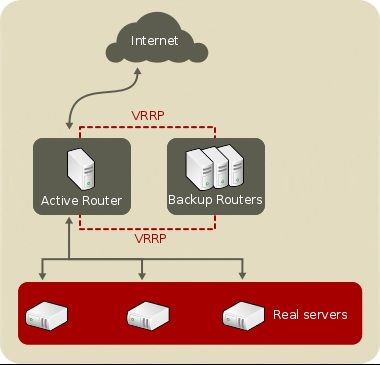
2.1. A Basic Keepalived Load Balancer Configurat ion
Figure 2.1, “ A Basic Load Balancer Configuration” shows a simple Keepalived Load Balancer
configuration consisting of two layers. On the first layer is one active and several backup LVS router.
Each LVS router has two network interfaces, one interface on the Internet and one on the private
network, enabling them to regulate traffic between the two networks. For this example the active router
is using Network Address Translation or NAT to direct traffic from the Internet to a variable number of
real servers on the second layer, which in turn provide the necessary services. Therefore, the real
servers in this example are connected to a dedicated private network segment and pass all public
traffic back and forth through the active LVS router. To the outside world, the servers appears as one
entity.
4Chapt er 2 . Keepalived O verview
Fig u re 2.1. A B asic Lo ad B alan cer C o n f ig u rat io n
Service requests arriving at the LVS router are addressed to a virtual IP address, or VIP. This is a
publicly-routable address the administrator of the site associates with a fully-qualified domain name,
such as www.example.com, and is assigned to one or more virtual servers. A virtual server is a service
configured to listen on a specific virtual IP. A VIP address migrates from one LVS router to the other
during a failover, thus maintaining a presence at that IP address (also known as floating IP
addresses).
VIP addresses may be assigned to the same device which connects the LVS router to the Internet. For
instance, if eth0 is connected to the Internet, then multiple virtual servers can be assigned to eth0 .
Alternatively, each virtual server can be associated with a separate device per service. For example,
HTTP traffic can be handled on eth0 at 192.168.1.111 while FTP traffic can be handled on eth0 at
192.168.1.222.
In a deployment scenario involving both one active and one passive router, the role of the active
router is to redirect service requests from virtual IP addresses to the real servers. The redirection is
based on one of eight supported load-balancing algorithms described further in Section 2.3,
“ keepalived Scheduling Overview” .
The active router also dynamically monitors the overall health of the specific services on the real
servers through three built-in health checks: simple TCP connect, HTTP, and HTTPS. For TCP
connect, the active router will periodically check that it can connect to the real servers on a certain
port. For HTTP and HTTPS, the active router will periodically fetch a URL on the real servers and
verify its content.
The backup routers perform the role of standby systems. Router failover is handled by VRRP. On
startup, all routers will join a multicast group. This multicast group is used to send and receive VRRP
advertisements. Since VRRP is a priority based protocol, the router with the highest priority is elected
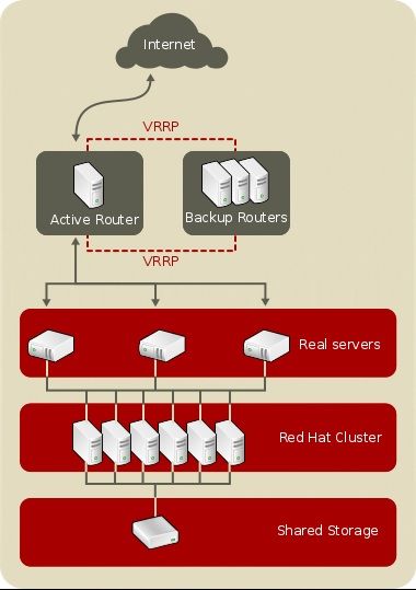
5Red Hat Ent erprise Linux 7 Load Balancer Administ rat ion the master. Once a router has been elected master, it is responsible for sending VRRP advertisements at periodic intervals to the multicast group. If the backup routers fail to receive advertisements within a certain time period (based on the advertisement interval), a new master will be elected. The new master will take over the VIP and send an Address Resolution Protocol (ARP) message. When a router returns to active service, it may either become a backup or a master. The behavior is determined by the router's priority. The simple, two-layered configuration used in Figure 2.1, “ A Basic Load Balancer Configuration” is best for serving data which does not change very frequently — such as static webpages — because the individual real servers do not automatically sync data between each node. 2.2. A T hree-T ier keepalived Load Balancer Configurat ion Figure 2.2, “ A Three-Tier Load Balancer Configuration” shows a typical three-tier Keepalived Load Balancer topology. In this example, the active LVS router routes the requests from the Internet to the pool of real servers. Each of the real servers then accesses a shared data source over the network. 6
Chapt er 2 . Keepalived O verview
Fig u re 2.2. A T h ree- T ier Lo ad B alan cer C o n f ig u rat io n
This configuration is ideal for busy FTP servers, where accessible data is stored on a central, highly
available server and accessed by each real server via an exported NFS directory or Samba share.
This topology is also recommended for websites that access a central, highly available database for
transactions. Additionally, using an active-active configuration with the Load Balancer Add-on,
administrators can configure one high-availability cluster to serve both of these roles
simultaneously.
The third tier in the above example does not have to use the Load Balancer Add-on, but failing to use
a highly available solution would introduce a critical single point of failure.
2.3. keepalived Scheduling Overview
Using Keepalived provides a great deal of flexibility in distributing traffic across real servers, in part
7Red Hat Ent erprise Linux 7 Load Balancer Administ rat ion
due to the variety of scheduling algorithms supported. Load balancing is superior to less flexible
methods, such as Round-Robin DNS where the hierarchical nature of D NS and the caching by client
machines can lead to load imbalances. Additionally, the low-level filtering employed by the LVS
router has advantages over application-level request forwarding because balancing loads at the
network packet level causes minimal computational overhead and allows for greater scalability.
Using assigned weights gives arbitrary priorities to individual machines. Using this form of
scheduling, it is possible to create a group of real servers using a variety of hardware and software
combinations and the active router can evenly load each real server.
The scheduling mechanism for Keepalived is provided by a collection of kernel patches called IP
Virtual Server or IPVS modules. These modules enable layer 4 (L4) transport layer switching, which is
designed to work well with multiple servers on a single IP address.
To track and route packets to the real servers efficiently, IPVS builds an IPVS table in the kernel. This
table is used by the active LVS router to redirect requests from a virtual server address to and
returning from real servers in the pool.
2.3.1. Keepalived Scheduling Algorit hms
The structure that the IPVS table takes depends on the scheduling algorithm that the administrator
chooses for any given virtual server. To allow for maximum flexibility in the types of services you can
cluster and how these services are scheduled, Keepalived supports the following scheduling
algorithms listed below.
Round-Robin Scheduling
D istributes each request sequentially around the pool of real servers. Using this algorithm,
all the real servers are treated as equals without regard to capacity or load. This
scheduling model resembles round-robin D NS but is more granular due to the fact that it is
network-connection based and not host-based. Load Balancer round-robin scheduling
also does not suffer the imbalances caused by cached D NS queries.
Weighted Round-Robin Scheduling
D istributes each request sequentially around the pool of real servers but gives more jobs to
servers with greater capacity. Capacity is indicated by a user-assigned weight factor, which
is then adjusted upward or downward by dynamic load information.
Weighted round-robin scheduling is a preferred choice if there are significant differences in
the capacity of real servers in the pool. However, if the request load varies dramatically, the
more heavily weighted server may answer more than its share of requests.
Least-Connection
D istributes more requests to real servers with fewer active connections. Because it keeps
track of live connections to the real servers through the IPVS table, least-connection is a
type of dynamic scheduling algorithm, making it a better choice if there is a high degree of
variation in the request load. It is best suited for a real server pool where each member node
has roughly the same capacity. If a group of servers have different capabilities, weighted
least-connection scheduling is a better choice.
Weighted Least-Connections
D istributes more requests to servers with fewer active connections relative to their
capacities. Capacity is indicated by a user-assigned weight, which is then adjusted upward
or downward by dynamic load information. The addition of weighting makes this algorithm
ideal when the real server pool contains hardware of varying capacity.
8Chapt er 2 . Keepalived O verview
Locality-Based Least-Connection Scheduling
D istributes more requests to servers with fewer active connections relative to their
destination IPs. This algorithm is designed for use in a proxy-cache server cluster. It routes
the packets for an IP address to the server for that address unless that server is above its
capacity and has a server in its half load, in which case it assigns the IP address to the
least loaded real server.
Locality-Based Least-Connection Scheduling with Replication Scheduling
D istributes more requests to servers with fewer active connections relative to their
destination IPs. This algorithm is also designed for use in a proxy-cache server cluster. It
differs from Locality-Based Least-Connection Scheduling by mapping the target IP address
to a subset of real server nodes. Requests are then routed to the server in this subset with
the lowest number of connections. If all the nodes for the destination IP are above capacity,
it replicates a new server for that destination IP address by adding the real server with the
least connections from the overall pool of real servers to the subset of real servers for that
destination IP. The most loaded node is then dropped from the real server subset to prevent
over-replication.
Destination Hash Scheduling
D istributes requests to the pool of real servers by looking up the destination IP in a static
hash table. This algorithm is designed for use in a proxy-cache server cluster.
Source Hash Scheduling
D istributes requests to the pool of real servers by looking up the source IP in a static hash
table. This algorithm is designed for LVS routers with multiple firewalls.
Shortest Expected Delay
D istributes connection requests to the server that has the shortest delay expected based on
number of connections on a given server divided by its assigned weight.
Never Queue
A two-pronged scheduler that first finds and sends connection requests to a server that is
idling, or has no connections. If there are no idling servers, the scheduler defaults to the
server that has the least delay in the same manner as Shortest Expected Delay.
2.3.2. Server Weight and Scheduling
The administrator of Load Balancer can assign a weight to each node in the real server pool. This
weight is an integer value which is factored into any weight-aware scheduling algorithms (such as
weighted least-connections) and helps the LVS router more evenly load hardware with different
capabilities.
Weights work as a ratio relative to one another. For instance, if one real server has a weight of 1 and
the other server has a weight of 5, then the server with a weight of 5 gets 5 connections for every 1
connection the other server gets. The default value for a real server weight is 1.
Although adding weight to varying hardware configurations in a real server pool can help load-
balance the cluster more efficiently, it can cause temporary imbalances when a real server is
introduced to the real server pool and the virtual server is scheduled using weighted least-
connections. For example, suppose there are three servers in the real server pool. Servers A and B
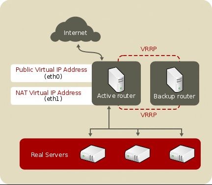
9Red Hat Ent erprise Linux 7 Load Balancer Administ rat ion are weighted at 1 and the third, server C, is weighted at 2. If server C goes down for any reason, servers A and B evenly distributes the abandoned load. However, once server C comes back online, the LVS router sees it has zero connections and floods the server with all incoming requests until it is on par with servers A and B. 2.4 . Rout ing Met hods Red Hat Enterprise Linux uses Network Address Translation (NAT routing) or direct routing for Keepalived. This allows the administrator tremendous flexibility when utilizing available hardware and integrating the Load Balancer into an existing network. 2.4 .1. NAT Rout ing Figure 2.3, “ Load Balancer Implemented with NAT Routing” , illustrates Load Balancer utilizing NAT routing to move requests between the Internet and a private network. Fig u re 2.3. Lo ad B alan cer Imp lemen t ed wit h N AT R o u t in g In the example, there are two NICs in the active LVS router. The NIC for the Internet has a real IP address and a floating IP address on eth0. The NIC for the private network interface has a real IP address and a floating IP address on eth1. In the event of failover, the virtual interface facing the Internet and the private facing virtual interface are taken-over by the backup LVS router simultaneously. All of the real servers located on the private network use the floating IP for the NAT router as their default route to communicate with the active LVS router so that their abilities to respond to requests from the Internet is not impaired. 10
Chapt er 2 . Keepalived O verview
In this example, the LVS router's public floating IP address and private NAT floating IP address are
assigned to physical NICs. While it is possible to associate each floating IP address to its own
physical device on the LVS router nodes, having more than two NICs is not a requirement.
Using this topology, the active LVS router receives the request and routes it to the appropriate server.
The real server then processes the request and returns the packets to the LVS router which uses
network address translation to replace the address of the real server in the packets with the LVS
router's public VIP address. This process is called IP masquerading because the actual IP addresses
of the real servers is hidden from the requesting clients.
Using this NAT routing, the real servers may be any kind of machine running various operating
systems. The main disadvantage is that the LVS router may become a bottleneck in large cluster
deployments because it must process outgoing as well as incoming requests.
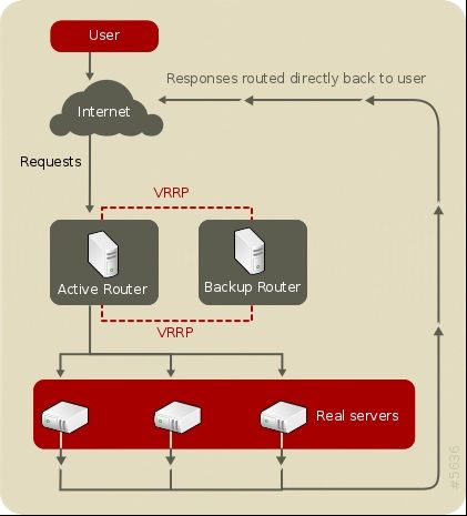
2.4 .2. Direct Rout ing
Building a Load Balancer setup that uses direct routing provides increased performance benefits
compared to other Load Balancer networking topologies. D irect routing allows the real servers to
process and route packets directly to a requesting user rather than passing all outgoing packets
through the LVS router. D irect routing reduces the possibility of network performance issues by
relegating the job of the LVS router to processing incoming packets only.
11Red Hat Ent erprise Linux 7 Load Balancer Administ rat ion
Fig u re 2.4 . Lo ad B alan cer Imp lemen t ed wit h D irect R o u t in g
In the typical direct routing Load Balancer setup, the LVS router receives incoming server requests
through the virtual IP (VIP) and uses a scheduling algorithm to route the request to the real servers.
The real server processes the request and sends the response directly to the client, bypassing the
LVS router. This method of routing allows for scalability in that real servers can be added without the
added burden on the LVS router to route outgoing packets from the real server to the client, which
can become a bottleneck under heavy network load.
2 .4 .2 .1 . Dire ct Ro ut ing and t he ARP Lim it at io n
While there are many advantages to using direct routing in Load Balancer , there are limitations as
well. The most common issue with Load Balancer via direct routing is with Address Resolution Protocol
(ARP).
In typical situations, a client on the Internet sends a request to an IP address. Network routers
typically send requests to their destination by relating IP addresses to a machine's MAC address with
ARP. ARP requests are broadcast to all connected machines on a network, and the machine with the
correct IP/MAC address combination receives the packet. The IP/MAC associations are stored in an
ARP cache, which is cleared periodically (usually every 15 minutes) and refilled with IP/MAC
associations.
The issue with ARP requests in a direct routing Load Balancer setup is that because a client request
to an IP address must be associated with a MAC address for the request to be handled, the virtual IP
address of the Load Balancer system must also be associated to a MAC as well. However, since both
the LVS router and the real servers all have the same VIP, the ARP request will be broadcast to all the
machines associated with the VIP. This can cause several problems, such as the VIP being
associated directly to one of the real servers and processing requests directly, bypassing the LVS
router completely and defeating the purpose of the Load Balancer setup.
To solve this issue, ensure that the incoming requests are always sent to the LVS router rather than
one of the real servers. This can be done by using either the arptabl es_jf or the i ptabl es packet
filtering tool for the following reasons:
The arptabl es_jf prevents ARP from associating VIPs with real servers.
The i ptabl es method completely sidesteps the ARP problem by not configuring VIPs on real
servers in the first place.
2.5. Persist ence and Firewall Marks wit h Keepalived
In certain situations, it may be desirable for a client to reconnect repeatedly to the same real server,
rather than have a load balancing algorithm send that request to the best available server. Examples
of such situations include multi-screen web forms, cookies, SSL, and FTP connections. In these
cases, a client may not work properly unless the transactions are being handled by the same server
to retain context. Keepalived provides two different features to handle this: persistence and firewall
marks.
2.5.1. Persist ence
When enabled, persistence acts like a timer. When a client connects to a service, Load Balancer
remembers the last connection for a specified period of time. If that same client IP address connects
again within that period, it is sent to the same server it connected to previously — bypassing the
load-balancing mechanisms. When a connection occurs outside the time window, it is handled
according to the scheduling rules in place.
12Chapt er 2 . Keepalived O verview
Persistence also allows the administrator to specify a subnet mask to apply to the client IP address
test as a tool for controlling what addresses have a higher level of persistence, thereby grouping
connections to that subnet.
Grouping connections destined for different ports can be important for protocols which use more
than one port to communicate, such as FTP. However, persistence is not the most efficient way to
deal with the problem of grouping together connections destined for different ports. For these
situations, it is best to use firewall marks.
2.5.2. Firewall Marks
Firewall marks are an easy and efficient way to a group ports used for a protocol or group of related
protocols. For instance, if Load Balancer is deployed to run an e-commerce site, firewall marks can
be used to bundle HTTP connections on port 80 and secure, HTTPS connections on port 443. By
assigning the same firewall mark to the virtual server for each protocol, state information for the
transaction can be preserved because the LVS router forwards all requests to the same real server
after a connection is opened.
Because of its efficiency and ease-of-use, administrators of Load Balancer should use firewall marks
instead of persistence whenever possible for grouping connections. However, administrators should
still add persistence to the virtual servers in conjunction with firewall marks to ensure the clients are
reconnected to the same server for an adequate period of time.
13Red Hat Ent erprise Linux 7 Load Balancer Administ rat ion
Chapter 3. Setting Up Load Balancer Prerequisites for
Keepalived
Load Balancer using Keealived consists of two basic groups: the LVS routers and the real servers.
To prevent a single point of failure, each groups should contain at least two member systems.
The LVS router group should consist of two identical or very similar systems running Red Hat
Enterprise Linux. One will act as the active LVS router while the other stays in hot standby mode, so
they need to have as close to the same capabilities as possible.
Before choosing and configuring the hardware for the real server group, determine which of the three
Load Balancer topologies to use.
3.1. T he NAT Load Balancer Net work
The NAT topology allows for great latitude in utilizing existing hardware, but it is limited in its ability
to handle large loads because all packets going into and coming out of the pool pass through the
Load Balancer router.
N et wo rk Layo u t
The topology for Load Balancer using NAT routing is the easiest to configure from a
network layout perspective because only one access point to the public network is needed.
The real servers pass all requests back through the LVS router so they are on their own
private network.
H ard ware
The NAT topology is the most flexible in regards to hardware because the real servers do
not need to be Linux machines to function correctly. In a NAT topology, each real server
only needs one NIC since it will only be responding to the LVS router. The LVS routers, on
the other hand, need two NICs each to route traffic between the two networks. Because this
topology creates a network bottleneck at the LVS router, gigabit Ethernet NICs can be
employed on each LVS router to increase the bandwidth the LVS routers can handle. If
gigabit Ethernet is employed on the LVS routers, any switch connecting the real servers to
the LVS routers must have at least two gigabit Ethernet ports to handle the load efficiently.
So f t ware
Because the NAT topology requires the use of i ptabl es for some configurations, there
can be a fair amount of software configuration outside of Keepalived. In particular, FTP
services and the use of firewall marks requires extra manual configuration of the LVS
routers to route requests properly.
3.1.1. Configuring Net work Int erfaces for Load Balancer wit h NAT
To set up Load Balancer with NAT, you must first configure the network interfaces for the public
network and the private network on the LVS routers. In this example, the LVS routers' public interfaces
(eth0 ) will be on the 192.168.26/24 network (This is not a routable IP, but assume there is a firewall
in front of the LVS router) and the private interfaces which link to the real servers (eth1) will be on the
10.11.12/24 network.
14Chapt er 3. Set t ing Up Load Balancer Prerequisit es for Keepalived
Important
Note that editing of the following files pertain to the netwo rk service and the Load Balancer is
not compatible with the Netwo rkManag er service.
So on the active or primary LVS router node, the public interface's network script,
/etc/sysco nfi g /netwo rk-scri pts/i fcfg -eth0 , could look something like this:
DEVICE=eth0
BOOTPROTO=static
ONBOOT=yes
IPADDR=192.168.26.9
NETMASK=255.255.255.0
GATEWAY=192.168.26.254
The /etc/sysco nfi g /netwo rk-scri pts/i fcfg -eth1 for the private NAT interface on the LVS
router could look something like this:
DEVICE=eth1
BOOTPROTO=static
ONBOOT=yes
IPADDR=10.11.12.9
NETMASK=255.255.255.0
In this example, the VIP for the LVS router's public interface will be 192.168.26.10 and the VIP for the
NAT or private interface will be 10.11.12.10. So, it is essential that the real servers route requests back
to the VIP for the NAT interface.
Important
The sample Ethernet interface configuration settings in this section are for the real IP
addresses of an LVS router and not the floating IP addresses.
After configuring the primary LVS router node's network interfaces, configure the backup LVS router's
real network interfaces — taking care that none of the IP address conflict with any other IP addresses
on the network.
Important
Be sure each interface on the backup node services the same network as the interface on
primary node. For instance, if eth0 connects to the public network on the primary node, it must
also connect to the public network on the backup node as well.
3.1.2. Rout ing on t he Real Servers
The most important thing to remember when configuring the real servers network interfaces in a NAT
topology is to set the gateway for the NAT floating IP address of the LVS router. In this example, that
address is 10.11.12.10.
15Red Hat Ent erprise Linux 7 Load Balancer Administ rat ion
Note
Once the network interfaces are up on the real servers, the machines will be unable to ping or
connect in other ways to the public network. This is normal. You will, however, be able to ping
the real IP for the LVS router's private interface, in this case 10.11.12.9.
So the real server's /etc/sysco nfi g /netwo rk-scri pts/i fcfg -eth0 file could look similar to
this:
DEVICE=eth0
ONBOOT=yes
BOOTPROTO=static
IPADDR=10.11.12.1
NETMASK=255.255.255.0
GATEWAY=10.11.12.10
Warning
If a real server has more than one network interface configured with a G AT EWAY = line, the first
one to come up will get the gateway. Therefore if both eth0 and eth1 are configured and
eth1 is used for Load Balancer, the real servers may not route requests properly.
It is best to turn off extraneous network interfaces by setting O NBO O T = no in their network
scripts within the /etc/sysco nfi g /netwo rk-scri pts/ directory or by making sure the
gateway is correctly set in the interface which comes up first.
3.1.3. Enabling NAT Rout ing on t he LVS Rout ers
In a simple NAT Load Balancer configuration where each clustered service uses only one port, like
HTTP on port 80, the administrator needs only to enable packet forwarding on the LVS routers for the
requests to be properly routed between the outside world and the real servers. However, more
configuration is necessary when the clustered services require more than one port to go to the same
real server during a user session.
Once forwarding is enabled on the LVS routers and the real servers are set up and have the clustered
services running, use the keepal i ved to configure IP information.
Warning
D o not configure the floating IP for eth0 or eth1 by manually editing network scripts or using
a network configuration tool. Instead, configure them via keepal i ved . co nf file.
When finished, start the keepal i ved service. Once it is up and running, the active LVS router will
begin routing requests to the pool of real servers.
3.2. Load Balancer via Direct Rout ing
16Chapt er 3. Set t ing Up Load Balancer Prerequisit es for Keepalived
D irect routing allows real servers to process and route packets directly to a requesting user rather
than passing outgoing packets through the LVS router. D irect routing requires that the real servers
be physically connected to a network segment with the LVS router and be able to process and direct
outgoing packets as well.
N et wo rk Layo u t
In a direct routing Load Balancer setup, the LVS router needs to receive incoming requests
and route them to the proper real server for processing. The real servers then need to
directly route the response to the client. So, for example, if the client is on the Internet, and
sends the packet through the LVS router to a real server, the real server must be able to go
directly to the client via the Internet. This can be done by configuring a gateway for the real
server to pass packets to the Internet. Each real server in the server pool can have its own
separate gateway (and each gateway with its own connection to the Internet), allowing for
maximum throughput and scalability. For typical Load Balancer setups, however, the real
servers can communicate through one gateway (and therefore one network connection).
H ard ware
The hardware requirements of a Load Balancer system using direct routing is similar to
other Load Balancer topologies. While the LVS router needs to be running Red Hat
Enterprise Linux to process the incoming requests and perform load-balancing for the real
servers, the real servers do not need to be Linux machines to function correctly. The LVS
routers need one or two NICs each (depending on if there is a back-up router). You can use
two NICs for ease of configuration and to distinctly separate traffic — incoming requests are
handled by one NIC and routed packets to real servers on the other.
Since the real servers bypass the LVS router and send outgoing packets directly to a client,
a gateway to the Internet is required. For maximum performance and availability, each real
server can be connected to its own separate gateway which has its own dedicated
connection to the carrier network to which the client is connected (such as the Internet or an
intranet).
So f t ware
There is some configuration outside of keep alived that needs to be done, especially for
administrators facing ARP issues when using Load Balancer via direct routing. Refer to
Section 3.2.1, “ D irect Routing and arptabl es_jf” or Section 3.2.2, “ D irect Routing and
i ptabl es” for more information.
3.2.1. Direct Rout ing and arptabl es_jf
In order to configure direct routing using arptabl es_jf, each real server must have their virtual IP
address configured, so they can directly route packets. ARP requests for the VIP are ignored entirely
by the real servers, and any ARP packets that might otherwise be sent containing the VIPs are
mangled to contain the real server's IP instead of the VIPs.
Using the arptabl es_jf method, applications may bind to each individual VIP or port that the real
server is servicing. For example, the arptabl es_jf method allows multiple instances of Apache
HTTP Server to be running bound explicitly to different VIPs on the system. There are also significant
performance advantages to using arptabl es_jf over the i ptabl es option.
However, using the arptabl es_jf method, VIPs can not be configured to start on boot using
standard Red Hat Enterprise Linux system configuration tools.
To configure each real server to ignore ARP requests for each virtual IP addresses, perform the
following steps:
17Red Hat Ent erprise Linux 7 Load Balancer Administ rat ion
1. Create the ARP table entries for each virtual IP address on each real server (the real_ip is the
IP the director uses to communicate with the real server; often this is the IP bound to eth0 ):
arptables -A IN -d -j DROP
arptables -A OUT -s -j mangle --mangle-ip-s
This will cause the real servers to ignore all ARP requests for the virtual IP addresses, and
change any outgoing ARP responses which might otherwise contain the virtual IP so that
they contain the real IP of the server instead. The only node that should respond to ARP
requests for any of the VIPs is the current active LVS node.
2. Once this has been completed on each real server, save the ARP table entries by typing the
following commands on each real server:
servi ce arptabl es_jf save
chkco nfi g --l evel 234 5 arptabl es_jf o n
The chkco nfi g command will cause the system to reload the arptables configuration on
bootup — before the network is started.
3. Configure the virtual IP address on all real servers using i p ad d r to create an IP alias. For
example:
# i p ad d r ad d 19 2. 16 8. 76 . 24 d ev eth0
4. Configure Keepalived for D irect Routing. This can be done by adding lb_kind DR to the
keepal i ved . co nf file. Refer to Chapter 4, Initial Load Balancer Configuration with Keepalived
for more information.
3.2.2. Direct Rout ing and i ptabl es
You may also work around the ARP issue using the direct routing method by creating i ptabl es
firewall rules. To configure direct routing using i ptabl es, you must add rules that create a
transparent proxy so that a real server will service packets sent to the VIP address, even though the
VIP address does not exist on the system.
The i ptabl es method is simpler to configure than the arptabl es_jf method. This method also
circumvents the LVS ARP issue entirely, because the virtual IP address(es) only exist on the active
LVS director.
However, there are performance issues using the i ptabl es method compared to arptabl es_jf, as
there is overhead in forwarding/masquerading every packet.
You also cannot reuse ports using the i ptabl es method. For example, it is not possible to run two
separate Apache HTTP Server services bound to port 80, because both must bind to INADDR_ANY
instead of the virtual IP addresses.
To configure direct routing using the i ptabl es method, perform the following steps:
1. On each real server, run the following command for every VIP, port, and protocol (TCP or
UD P) combination intended to be serviced for the real server:
i ptabl es -t nat -A P R ER O UT ING -p -d --d po rt -j
R ED IR EC T
This command will cause the real servers to process packets destined for the VIP and port
that they are given.
18Chapt er 3. Set t ing Up Load Balancer Prerequisit es for Keepalived
2. Save the configuration on each real server:
# servi ce i ptabl es save
# chkco nfi g --l evel 234 5 i ptabl es o n
The commands above cause the system to reload the i ptabl es configuration on bootup —
before the network is started.
3.2.3. Direct Rout ing and sysctl
Another way to deal with the ARP limitation when employing D irect Routing is using the sysctl
interface. Administrators can configure two systcl settings such that the real server will not
announce the VIP in ARP requests and will not reply to ARP requests for the VIP address. To enable
this, run the following commands:
echo 1 > /proc/sys/net/ipv4/conf/eth0/arp_ignore
echo 2 > /proc/sys/net/ipv4/conf/eth0/arp_announce
Alternatively, you may add the following lines to /etc/sysctl.d/arp.conf:
net.ipv4.conf.eth0.arp_ignore = 1
net.ipv4.conf.eth0.arp_announce = 2
3.3. Put t ing t he Configurat ion T oget her
After determining which of the preceding routing methods to use, the hardware should be linked
together on the network.
Important
The adapter devices on the LVS routers must be configured to access the same networks. For
instance if eth0 connects to public network and eth1 connects to the private network, then
these same devices on the backup LVS router must connect to the same networks.
Also the gateway listed in the first interface to come up at boot time is added to the routing
table and subsequent gateways listed in other interfaces are ignored. This is especially
important to consider when configuring the real servers.
After physically connecting together the hardware, configure the network interfaces on the primary
and backup LVS routers. This can be done using a graphical application such as syst em- co n f ig -
n et wo rk or by editing the network scripts manually. For more information about adding devices
using syst em- co n f ig - n et wo rk, see the chapter titled Network Configuration in the Red Hat Enterprise
Linux Deployment Guide.
3.3.1. General Load Balancer Net working T ips
19Red Hat Ent erprise Linux 7 Load Balancer Administ rat ion
Configure the real IP addresses for both the public and private networks on the LVS routers before
attempting to configure Load Balancer using Keepalived. The sections on each topology give
example network addresses, but the actual network addresses are needed. Below are some useful
commands for bringing up network interfaces or checking their status.
B rin g in g U p R eal N et wo rk In t erf aces
To bring up a real network interface, use the following command as root, replacing N with
the number corresponding to the interface (eth0 and eth1).
/usr/sbi n/i fup ethN
Warning
D o not use the i fup scripts to bring up any floating IP addresses you may configure
using Keepalived (eth0 : 1 or eth1: 1). Use the servi ce or systemctl command
to start keepal i ved instead.
B rin g in g D o wn R eal N et wo rk In t erf aces
To bring down a real network interface, use the following command as root, replacing N
with the number corresponding to the interface (eth0 and eth1).
/usr/sbi n/i fd o wn ethN
C h eckin g t h e St at u s o f N et wo rk In t erf aces
If you need to check which network interfaces are up at any given time, type the following:
/usr/sbi n/i fco nfi g
To view the routing table for a machine, issue the following command:
/usr/sbi n/ro ute
3.4 . Mult i-port Services and Load Balancer
LVS routers under any topology require extra configuration when creating multi-port Load Balancer
services. Multi-port services can be created artificially by using firewall marks to bundle together
different, but related protocols, such as HTTP (port 80) and HTTPS (port 443), or when Load
Balancer is used with true multi-port protocols, such as FTP. In either case, the LVS router uses
firewall marks to recognize that packets destined for different ports, but bearing the same firewall
mark, should be handled identically. Also, when combined with persistence, firewall marks ensure
connections from the client machine are routed to the same host, as long as the connections occur
within the length of time specified by the persistence parameter.
Unfortunately, the mechanism used to balance the loads on the real servers — IPVS — can recognize
the firewall marks assigned to a packet, but cannot itself assign firewall marks. The job of assigning
firewall marks must be performed by the network packet filter, i ptabl es.
3.4 .1. Assigning Firewall Marks
To assign firewall marks to a packet destined for a particular port, the administrator must use
i ptabl es.
20Chapt er 3. Set t ing Up Load Balancer Prerequisit es for Keepalived
This section illustrates how to bundle HTTP and HTTPS as an example; however, FTP is another
commonly clustered multi-port protocol.
The basic rule to remember when using firewall marks is that for every protocol using a firewall mark
in Keepalived there must be a commensurate i ptabl es rule to assign marks to the network packets.
Before creating network packet filter rules, make sure there are no rules already in place. To do this,
open a shell prompt, login as root, and type:
/usr/sbi n/servi ce i ptabl es status
If i ptabl es is not running, the prompt will instantly reappear.
If i ptabl es is active, it displays a set of rules. If rules are present, type the following command:
/sbi n/servi ce i ptabl es sto p
If the rules already in place are important, check the contents of /etc/sysco nfi g /i ptabl es and
copy any rules worth keeping to a safe place before proceeding.
The first load balancer related configuring firewall rules is to allow VRRP traffic for the Keepalived
service to function.
/usr/sbin/iptables -I INPUT -p vrrp -j ACCEPT
Below are rules which assign the same firewall mark, 80, to incoming traffic destined for the floating
IP address, n.n.n.n, on ports 80 and 443.
/usr/sbin/iptables -t mangle -A PREROUTING -p tcp -d n.n.n.n/32 -m
multiport --dports 80,443 -j MARK --set-mark 80
Note that you must log in as root and load the module for i ptabl es before issuing rules for the first
time.
In the above i ptabl es commands, n.n.n.n should be replaced with the floating IP for your HTTP and
HTTPS virtual servers. These commands have the net effect of assigning any traffic addressed to the
VIP on the appropriate ports a firewall mark of 80, which in turn is recognized by IPVS and forwarded
appropriately.
Warning
The commands above will take effect immediately, but do not persist through a reboot of the
system.
3.5. Configuring FT P
File Transport Protocol (FTP) is an old and complex multi-port protocol that presents a distinct set of
challenges to an Load Balancer environment. To understand the nature of these challenges, you
must first understand some key things about how FTP works.
3.5.1. How FT P Works
With most other server client relationships, the client machine opens up a connection to the server on
a particular port and the server then responds to the client on that port. When an FTP client connects
21Red Hat Ent erprise Linux 7 Load Balancer Administ rat ion
to an FTP server it opens a connection to the FTP control port 21. Then the client tells the FTP server
whether to establish an active or passive connection. The type of connection chosen by the client
determines how the server responds and on what ports transactions will occur.
The two types of data connections are:
Act ive C o n n ect io n s
When an active connection is established, the server opens a data connection to the client
from port 20 to a high range port on the client machine. All data from the server is then
passed over this connection.
Passive C o n n ect io n s
When a passive connection is established, the client asks the FTP server to establish a
passive connection port, which can be on any port higher than 10,000. The server then
binds to this high-numbered port for this particular session and relays that port number
back to the client. The client then opens the newly bound port for the data connection. Each
data request the client makes results in a separate data connection. Most modern FTP
clients attempt to establish a passive connection when requesting data from servers.
Note
The client determines the type of connection, not the server. This means to effectively cluster
FTP, you must configure the LVS routers to handle both active and passive connections.
The FTP client/server relationship can potentially open a large number of ports that
Keepalived does not know about.
3.5.2. How T his Affect s Load Balancer Rout ing
IPVS packet forwarding only allows connections in and out of the cluster based on it recognizing its
port number or its firewall mark. If a client from outside the cluster attempts to open a port IPVS is not
configured to handle, it drops the connection. Similarly, if the real server attempts to open a
connection back out to the Internet on a port IPVS does not know about, it drops the connection.
This means all connections from FTP clients on the Internet must have the same firewall mark
assigned to them and all connections from the FTP server must be properly forwarded to the Internet
using network packet filtering rules.
Note
In order to enable passive FTP connections, ensure that you have the i p_vs_ftp kernel
module loaded, which you can do by running the command mo d pro be i p_vs_ftp as an
administrative user at a shell prompt.
3.5.3. Creat ing Net work Packet Filt er Rules
Before assigning any i ptabl es rules for FTP service, review the information in Section 3.4.1,
“ Assigning Firewall Marks” concerning multi-port services and techniques for checking the existing
network packet filtering rules.
22Chapt er 3. Set t ing Up Load Balancer Prerequisit es for Keepalived
Below are rules which assign the same firewall mark, 21, to FTP traffic.
3.5 .3.1 . Rule s fo r Act ive Co nne ct io ns
The rules for active connections tell the kernel to accept and forward connections coming to the
internal floating IP address on port 20 — the FTP data port.
The following i ptabl es command allows the LVS router to accept outgoing connections from the
real servers that IPVS does not know about:
/usr/sbi n/i ptabl es -t nat -A P O ST R O UT ING -p tcp -s n.n.n. 0 /24 --spo rt 20 -
j MASQ UER AD E
In the i ptabl es command, n.n.n should be replaced with the first three values for the floating IP for
the NAT interface's internal network interface defined virtual_server section of the
keepal i ved . co nf file.
3.5 .3.2 . Rule s fo r Passive Co nne ct io ns
The rules for passive connections assign the appropriate firewall mark to connections coming in
from the Internet to the floating IP for the service on a wide range of ports — 10,000 to 20,000.
Warning
If you are limiting the port range for passive connections, you must also configure the VSFTP
server to use a matching port range. This can be accomplished by adding the following lines
to /etc/vsftpd . co nf:
pasv_mi n_po rt= 10 0 0 0
pasv_max_po rt= 20 0 0 0
Setting pasv_ad d ress to override the real FTP server address should not be used since it is
updated to the virtual IP address by LVS.
For configuration of other FTP servers, consult the respective documentation.
This range should be a wide enough for most situations; however, you can increase this number to
include all available non-secured ports by changing 10 0 0 0 : 20 0 0 0 in the commands below to
10 24 : 6 5535.
The following i ptabl es commands have the net effect of assigning any traffic addressed to the
floating IP on the appropriate ports a firewall mark of 21, which is in turn recognized by IPVS and
forwarded appropriately:
/usr/sbi n/i ptabl es -t mang l e -A P R ER O UT ING -p tcp -d n.n.n.n/32 --d po rt 21
-j MAR K --set-mark 21
/usr/sbi n/i ptabl es -t mang l e -A P R ER O UT ING -p tcp -d n.n.n.n/32 --d po rt
10 0 0 0 : 20 0 0 0 -j MAR K --set-mark 21
In the i ptabl es commands, n.n.n.n should be replaced with the floating IP for the FTP virtual server
defined in the virutal_server subsection of the keepal i ved . co nf file.
23Red Hat Ent erprise Linux 7 Load Balancer Administ rat ion
Warning
The commands above take effect immediately, but do not persist through a reboot of the
system.
Finally, you need to be sure that the appropriate service is set to activate on the proper runlevels.
3.6. Saving Net work Packet Filt er Set t ings
After configuring the appropriate network packet filters for your situation, save the settings so they get
restored after a reboot. For i ptabl es, type the following command:
/usr/sbi n/servi ce i ptabl es save
This saves the settings in /etc/sysco nfi g /i ptabl es so they can be recalled at boot time.
Once this file is written, you are able to use the /usr/sbi n/servi ce command to start, stop, and
check the status (using the status switch) of i ptabl es. The /usr/sbi n/servi ce will automatically
load the appropriate module for you.
Finally, you need to be sure the appropriate service is set to activate on the proper runlevels.
3.7. T urning on Packet Forwarding and Nonlocal Binding
In order for the Keepalived service to forward network packets properly to the real servers, each router
node must have IP forwarding turned on in the kernel. Log in as root and change the line which
reads net. i pv4 . i p_fo rward = 0 in /etc/sysctl . co nf to the following:
net.ipv4.ip_forward = 1
The changes take effect when you reboot the system.
Load balancing in HAProxy also requires the ability to bind to an IP address that are nonlocal,
meaning that it is not assigned to a device on the local system. This allows a running load balancer
instance to bind to a an IP that is not local for failover.
To enable, edit the line in /etc/sysctl . co nf that reads net. i pv4 . i p_no nl o cal _bi nd to the
following:
net.ipv4.ip_nonlocal_bind = 1
The changes take effect when you reboot the system.
To check if IP forwarding is turned on, issue the following command as root:
/usr/sbi n/sysctl net. i pv4 . i p_fo rward
To check if nonlocal binding is turned on, issue the following command as root:
/usr/sbi n/sysctl net. i pv4 . i p_no nl o cal _bi nd
If both commands the above command returns a 1, then the respective settings are enabled.
3.8. Configuring Services on t he Real Servers
24Chapt er 3. Set t ing Up Load Balancer Prerequisit es for Keepalived
3.8. Configuring Services on t he Real Servers
If the real servers are Red Hat Enterprise Linux systems, set the appropriate server daemons to
activate at boot time. These daemons can include httpd for Web services or xi netd for FTP or
Telnet services.
It may also be useful to access the real servers remotely, so the sshd daemon should also be
installed and running.
25Red Hat Ent erprise Linux 7 Load Balancer Administ rat ion
Chapter 4. Initial Load Balancer Configuration with Keepalived
After installing Load Balancer packages, you must take some basic steps to set up the LVS router
and the real servers for use with Keepalived. This chapter covers these initial steps in detail.
4 .1. A Basic Keepalived configurat ion
In this basic example, two systems are configured as load balancers. LB1 (Active) and LB2 (Backup)
will be routing requests for a pool of four Web servers running httpd with real IP addresses
numbered 191.168.1.20 to 192.168.1.24, sharing a virtual IP address of 192.168.1.11. Each load
balancer has two interfaces (eth0 and eth1), one for handling external Internet traffic, and the other
for routing requests to the real servers. The load balancing algorithm used is Round Robin and the
routing method will be Network Address Translation.
4 .1.1. Creat ing t he keeapl i ved . co nf file
Keepalived is configured via the keepal i ved . co nf file. To create a load balancer topology like the
example shown in Section 4.1, “ A Basic Keepalived configuration” , use a text editor to open
keepal i ved . co nf. For example:
vi /etc/keepalived/keepalived.conf
A basic load balanced system with the configuration as detailed in Section 4.1, “ A Basic Keepalived
configuration” has a keepal i ved . co nf file as explained in the following code sections.
4 .1 .1 .1 . Glo bal De finit io ns
The Global D efinitions section of the keepal i ved . co nf file allows administrators to specify
notification details when changes to the load balancer occurs. Note that the Glogal D efinitions are
optional and are not required for Keepalived configuration.
global_defs {
notification_email {
admin@ example.com
}
notification_email_from noreply@ example.com
smtp_server 127.0.0.1
smtp_connect_timeout 60
}
The notification_email is the administrator of the load balancer, while the
notification_email_from is an address that sends the load balancer state changes. The SMTP
specific configuration specifies the mail server from which the notifications are mailed.
4 .1 .1 .2 . VRRP Inst ance
26You can also read