Design and Shape Optimization of a Biodegradable Polymeric Stent for Curved Arteries Using FEM - Frontiers
←
→
Page content transcription
If your browser does not render page correctly, please read the page content below
ORIGINAL RESEARCH
                                                                                                                                               published: 21 May 2021
                                                                                                                                      doi: 10.3389/fmech.2021.689002

                                           Design and Shape Optimization of a
                                           Biodegradable Polymeric Stent for
                                           Curved Arteries Using FEM
                                           Yasaman Baradaran 1, Mostafa Baghani 1, Morteza Kazempour 1, Seyed Kianoosh Hosseini 2,
                                           Morad Karimpour 1 and Majid Baniassadi 1*
                                           1
                                             School of Mechanical Engineering, College of Engineering, University of Tehran, Tehran, Iran, 2Department of Cardiovascular
                                           Disorders, Division of Interventional Cardiology, Tehran University of Medical Sciences, Tehran, Iran

                                           Stent treatment has revealed safe and efficient outcomes for straight arteries, while it is still
                                           challenging for curved coronary arteries. On the one hand, a stent should be flexible
                                           enough to take the artery’s curvature with the least stress to the artery wall. On the other
                                           hand, it has to be strong enough to prevent any artery diameter reduction after the implant.
                                           In this work, the genetic algorithm multi-objective optimization method is exploited to
                                           provide a Pareto set and to design a curvature stent. The design has been performed
                                           based on the appropriate flexibility and radial strength design, depending on the
                          Edited by:       characteristics of a particular case study. In the optimization procedure, flexibility and
                Masoumeh Ozmaian,
        University of Texas at Austin,
                                           radial strength have been evaluated based on ASTM standard mechanical tests. These
                        United States      tests have been parametrically simulated using the finite element method. The strut
                     Reviewed by:          curvature is formed by the spline curvature, whose middle point coordinates are two
                    Hossein Darijani,      of the optimization variables. The other optimization variable is the thickness of the stent.
        Shahid Bahonar University of
                       Kerman, Iran        Based on the Pareto set achieved from the optimization, five different stent designs have
                   Abbas Montazeri,        been proposed. In these designs, the middle part of the stent is stiffer (in the plaque
            K. N. Toosi University of
                    Technology, Iran
                                           aggregated) and benefits more radial strength rather than flexibility. At the stent’s
                 *Correspondence:
                                           extremes, where more deformation takes place, flexibility is weighted more than radial
                    Majid Baniassadi       strength. These five design sets differ in their objective weight ratios. At the end of this
                m.baniassadi@ut.ac.ir      research, their implementation in a curved vessel is simulated in ABAQUS/CAE, and von
                                           Mises stress distribution, maximum von Mises stress, and stent recoil after imposing the
                    Specialty section:
         This article was submitted to     stent have been analyzed. The obtained Pareto front can also be a useful guide for
          Biomechanical Engineering,       physicians to design and manufacture customized stents for each patient.
               a section of the journal
  Frontiers in Mechanical Engineering      Keywords: polymeric stents, shape optimization, curved artery, finite element method, GA multi-objective
          Received: 31 March 2021          optimization
           Accepted: 29 April 2021
           Published: 21 May 2021
                                           INTRODUCTION
                            Citation:
             Baradaran Y, Baghani M,       Coronary artery disease causes artery narrowing that can sometimes lead to complete blockage
          Kazempour M, Hosseini SK,        (stenosis). When this happens in coronary arteries, blood supply restricts and heart muscle cells die,
Karimpour M and Baniassadi M (2021)
                                           which leads to heart attack. In general, stenosis is manageable by treatment with stents or with a
 Design and Shape Optimization of a
   Biodegradable Polymeric Stent for
                                           bypass (Venkatraman et al., 2008). Stent treatment has revealed safe and efficient outcomes for
          Curved Arteries Using FEM.       straight arteries (Tambaca et al., 2011; Iqbal et al., 2015), while it is still challenging for curved
          Front. Mech. Eng 7:689002.       coronary arteries. Stenosis typically occurs at the angled sections of the vascular pathway like arches
    doi: 10.3389/fmech.2021.689002         and bifurcations (Tomita et al., 2015). The angular vessel gets straightened by stenting, and a hinge

Frontiers in Mechanical Engineering | www.frontiersin.org                          1                                             May 2021 | Volume 7 | Article 689002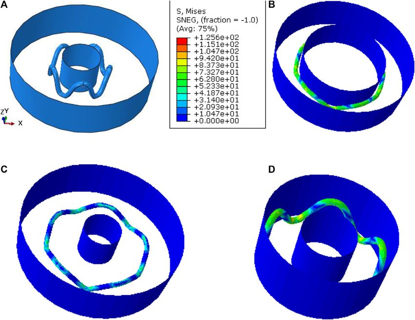
Baradaran et al.                                                                                                                   Stent for Curved Arteries

effect takes place at extremes of the stent. The maximum vessel                    (Torki et al., 2020). In 2017, Vishwanathan optimized the
stress is also exerted at hinge points (Ebrahimi et al., 2007; Wu                  structural shape of a stent, using NURBS for parameterization.
et al., 2007). Restenosis (disease re-occurrence) may occur if the                 Control point weights, strut thickness, and strut width were used
radial flexibility of the stent is too low (i.e., if the stent is too rigid).       as design variables for Latin hypercube sampling (LHS) in order
The stent should be flexible enough to take the curvature of the                    to generate a dataset for stent deployment simulations (Chen
artery with less stress to the artery wall. It should also be flexible              et al., 2019). Alaimo et al. proposed an optimization framework
during the implant procedure. If the stent is not flexible, it could                through a local modification of the planar strut profile (Alaimo
not track the catheter during the navigation inside a tortuous and                 et al., 2017). Li et al. proposed a Kriging surrogate model to
curved blood vessel (Santos et al., 2020).                                         optimize the geometries of a stent and length of the stent
    In 2020, Shen et al. worked on flexibility of a new self-                       dilatation balloon step by step (Li et al., 2017).
expandable tapered stent. Their results revealed that the                              The finite element method is an excellent technique to test and
increase in the stent link space width can contribute to the                       improve stent designs and performance from biomechanical
reduction in the peak stress. Therefore, tapered stents with                       aspects. In comparison with experimental investigations, the
high link space width will improve the stent flexibility (Shen                      FEM conveys data that are hard or impossible to be achieved
et al., 2020). Wei et al. investigated six stent structures into a                 in practice. It also brings about the opportunity to design and test
curved stenotic coronary artery. Their results showed that the                     different models with least cost and time spent until an optimal
Palmaz-Schatz–shaped stent had the greatest maximum plastic                        design is earned (Torki et al., 2020).
strain and the largest diameter change but the highest maximum                         In this work, using the finite element method, a stent is
von Mises stress on plaque and arterial intima and media (Wei                      designed to be implanted in a curved vessel. Its flexibility and
et al., 2019). Saito et al.’s investigation revealed that stent                    radial strength are geometrically optimized by the GA multi-
flexibility influences not only mechanical stress on the artery                      objective optimization method. Since a range of Pareto optimal
but also wall shear stress (WSS), which may induce local                           design parameter values are obtained, which can be used in
neointimal hyperplasia (Saito et al., 2020). Perrin et al.’s report                clinical design guides so as to accommodate variations
revealed that increasing vessel curvature leads to stent graft kinks               observed across different patients, polylactic acid is chosen as
and inadequate apposition against the arterial wall (Perrin et al.,                the material for the stent. Indeed, the reasons include ease of
2015). Kasiri reported that a double segment stent provides                        production, control over properties of the polymer, ready
higher flexibility, more conformity, and lower recoil (Kasiri                       availability, and versatility of manipulation (Venkatraman
and Kelly, 2011).                                                                  et al., 2008).
    There is still lack of conformability to the vessel wall when                      Stents can be made using additive manufacturing (AM) that
deployed at curved lesions. The stent should also be sufficiently                   builds models layer by layer from a computer-aided design
strong in order to prevent any artery diameter reduction after the                 (CAD) system and provides a fast and cost-effective process to
implant, since the artery wall applies dynamic and static load to                  develop more suitable biomedical products (Demir and Previtali,
the stent. In practice, this load will change depending on the                     2017; Guerra et al., 2017; Fathi et al., 2020). Various AM
artery anatomy shape.                                                              machines have been used in stent field processes, including
    Thus, a designer should consider both flexibility and radial                    fused deposition modeling (FDM). Specifically, FDM has been
strength as the main properties of a stent that is intended to be                  commonly used to fabricate stent scaffolds (Chung et al., 2018;
implanted in a curved vessel. Since these two parameters are                       Tabriz et al., 2019; Colpani et al., 2020). An FDM machine is
conflicting in a stent, a powerful method is required to find the                    composed basically of a double extruder head nozzle controlled
optimum design that meets the essentials. By comparing the                         by a CNC mechanism. FDM parts are produced by extruding
numerical results obtained from different design sets, the                         filaments of thermoplastic materials layer by layer onto the build
suggestion can be made to improve the existing design of a                         platform using a diameter extrusion head. The simplicity of the
stent (Mortier et al., 2010; Wu et al., 2010; Pant et al., 2012).                  FDM process makes it suitable for the rapid development of
However, the questions are whether the findings are the best                        molds (rapid tooling) (Hopkinson et al., 2006).
design and how to establish an optimal one in a systematic way                         One of the innovations of this work is that flexibility is
instead of it being based on a few empirical designs.                              preferred rather than radial strength in distal and proximal
    Since the optimization theory is a powerful and practical                      parts of the stent, while radial strength is preferred to
mathematical technique for determining the most profitable or                       flexibility in its middle part. Subsequently, geometric
least disadvantageous choice, out of a set of alternatives (Mehne                  parameters differ for extremes and middle section, but
and Mirjalili, 2020; Mirjalili et al., 2020a; Mirjalili et al., 2020b),            smoothness is considered to be kept all over the stent. In this
this paper attempts to explore the entire process for shape                        way, the stent recoil and stress distribution in both the artery wall
optimization of a stent and improve its mechanical properties                      and the stent are expected to be improved simultaneously
by utilizing the multi-objective optimization.                                     through the site.
    In 2020, Torki et al. designed and optimized a stent with the                      The main models used in the analysis of stents and the
optimization parameters including the longitudinal pattern (cell)                  description of the shape optimization problem will be shown
number, circular–circumferential pattern (cell) number,                            in this work. After the optimization procedure, five different
connection of cells by an N, M, or W type flex connector,                           design sets are devised according to the optimization Pareto
radius curve, thickness, and maximum and minimum width                             optimal solution. Their implementation in a curved artery is

Frontiers in Mechanical Engineering | www.frontiersin.org                      2                                       May 2021 | Volume 7 | Article 689002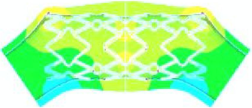
Baradaran et al.                                                                                                                   Stent for Curved Arteries

simulated, and the stresses and the recoil are compared among
these stents. The discussion of the obtained results and the final
conclusions are described at the end of this paper. The results of
this study show the merits of the spline-based parameterization
approach, which models a broader range of shapes than that was
previously possible with traditional approaches.

METHODOLOGY
Finite Element Method
In this study, two FEM models were built to study the stent’s
ABAQUS/Standard implicit solver. The radial strength after
dilation and the bending flexibility of the PLLA stent were
evaluated according to the American Society for Testing and
Materials (ASTM) standard. The meshing method is very
important, as it determines the total number of DOFs and the
accuracy of calculation greatly. The element types of meshes
decided for the stent were C3D20R, C3D15, and C3D10. The seed
size was linearly proportional to the thickness of the stent, since
thickness is one of the optimization variables. There are at least
                                                                           FIGURE 1 | Strut central line curvature, the middle point has variable x
three meshes in the thickness of the stent. The structure with one
                                                                           and y values (mm).
ring for radial strength simulation was meshed to about 2,140
elements. The whole stent for bending simulation was meshed to
about 24,060 elements.
   The ordinary numerical simulation demands only an                      [xmin,xmax] (Hua et al., 2020) with specified continuity
unalterable geometric model, whereas the optimization task                constraints, i.e., when the interval [xmin,xmax] is subdivided
requires a parameterized geometric model that is represented              by control points ξi such that xmin  ξ1 < . . .< ξq  xmax, then
by a set of shape design variables rather than constant values. The       within each subinterval [ξj,ξj+1), the function is a polynomial Pj
geometric model has to be rebuilt and re-meshed according to the          of specified degree (Bezhaev and Vasilenko, 2001). Control
updated design variables at the beginning of each optimization            points are used to determine the shape of a spline curve.
loop. Thus, all simulations were parametrically coded in                      In this study, the spline curve is used to design the strut
PYTHON, to be run in the ABAQUS/Standard implicit solver.                 curvature since it provides a flexible shape design by handling
In this way, not only was simple conformity with the optimization         control points while the curvature can retain its smoothness. The
algorithm conducted in MATLAB obtained, but also some                     spline is first drawn in a two-dimensional plane and then rolled
shortcomings of the ABAQUS/Standard implicit solver were                  over a cylindrical surface. It is defined by seven control points,
overcome.                                                                 among which the fourth one’s Cartesian coordinates x and y are
                                                                          two of the optimization variables. Groups of three first and last
GA Multi-objective Optimization                                           control points are very close to each other and have the same
A goal of this paper is to demonstrate a set of optimal stent             highs (y). They are defined to make the beginning and the end of
designs for a range of curved arteries. The multi-objective               the curve tangent to the horizon, and thus, smoothness will be
genetic algorithm is conducted in MATLAB. The population                  kept all over the structure and the curve will not be twisted
size and the iteration number are 80 and 100, respectively. For           (Figure 1).
each objective function calculation, the simulation is                        The stent is designed and optimized for a curved vessel with
performed in the ABAQUS/Standard implicit solver, and                     the curvature radius of 10 mm. The crimped diameter of the stent
the result is returned to MATLAB. We have tried to use                    is 1.5 mm, while it is meant to be dilated up to 3.2 mm. The stent
shape optimization to optimize the strut structure of a                   is constructed with 10 peak-to-valley struts (Figure 2) in the
stent, with the aim of increasing its flexibility and radial               circular direction. The total length of the stent consisting of 28
strength. The radial strength of the stent and its flexibility             rings is about 16.8 mm (which will be exactly determined after
during the implant procedure will be optimized                            optimization) (Figure 2). The width and height of each peak-to-
simultaneously.                                                           valley strut are 0.47 and 0.6, respectively.
                                                                              Studies show that, in curved vessels, larger strain is
Geometric Modeling                                                        observed around the center of stent than its two ends, while
The spline curve is a sufficiently general mathematical method             bending force is observed to be more in the ends (Wu et al.,
for defining arbitrarily smooth shaped curves and surfaces                 2007; Zhao et al., 2014) (Figure 3). It can be concluded that
(Gordon and Riesenfeld, 1974). The spline function f is a                 more stiffness is required in the middle part of the stent where
piecewise polynomial function defined on an interval                       the plaque is concentrated and stiffer and more load will be

Frontiers in Mechanical Engineering | www.frontiersin.org             3                                              May 2021 | Volume 7 | Article 689002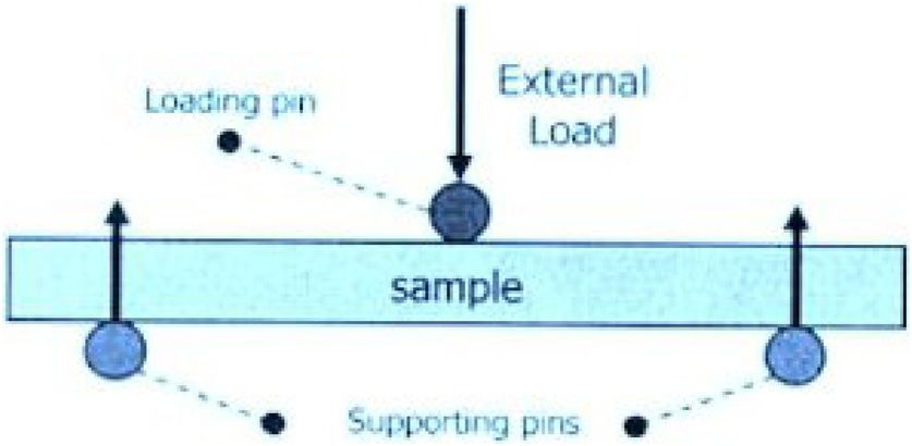
Baradaran et al.                                                                                                                        Stent for Curved Arteries

 FIGURE 2 | Stent design.

 FIGURE 3 | Deformation of a straight stent in a curved vessel (Wu et al., 2007).

TABLE 1 | Material properties of PLLA (Wang et al., 2017).                              MATERIALS
                                                                                3
Density                                                             1.25 g/cm
                                                                                        Poly-L-lactide acid (PLLA) was chosen as the stent material.
Young’s modulus                                                       3.3 GPa           Wang et al. (2017) evaluated constitutive data of PLLA at exactly
Poisson’s ratio                                                         0.3             37°C, which is the human body temperature. These data are used
Yield stress                                                         51.5 MPa
                                                                                        in this study for definition of material properties (Table 1).

                                                                                        Radial Strength
applied when the vessel is narrower: in other words, its two                            The FE model for evaluating the radial strength 37° of the stent
ends should be more flexible. Subsequently, in post-                                     was set according to the ASTM standard (ASTM F3067-14,
processing, the objective function weights are managed to                               2014). The test was driven in three static steps. In the first
be different for 16 middle rings and 8 rings of each side.                              step, the balloon dilates the stent to the pre-defined inner
Therefore, their geometries and mechanical behavior will                                diameter of 3.2 mm. In the second step, the stent is unloaded
differ too.                                                                             from the balloon pressure and has the chance to spring back. In
   Clinical studies have noted a proportional relationship between                      the third step, a 0.7 displacement in the radial direction is exerted
strut thickness and angiographic restenosis (Pache et al., 2003). The                   to the stent from an outer cylindrical displacement supplier with a
increase in strut thickness is effective to improve the radial                          low enough constant speed of 0.5 mm/s. In this step, the pressure
supporting ability of stents, but thicker struts will hamper the                        applied by the displacement supplier is increasing by diameter
blood flow, delay full neointimal coverage, and increase the risk of                     decrease, until it reaches the constant amount per diameter
subacute thrombosis (Hua et al., 2020). In this regard, thickness is                    displacement for a short distance, called collapse pressure. At
the other optimization variable in this work.                                           this level, the constancy of the pressure demonstrates the stent’s

Frontiers in Mechanical Engineering | www.frontiersin.org                           4                                       May 2021 | Volume 7 | Article 689002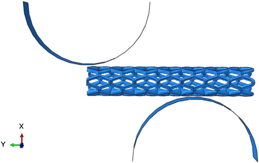
Baradaran et al. Stent for Curved Arteries
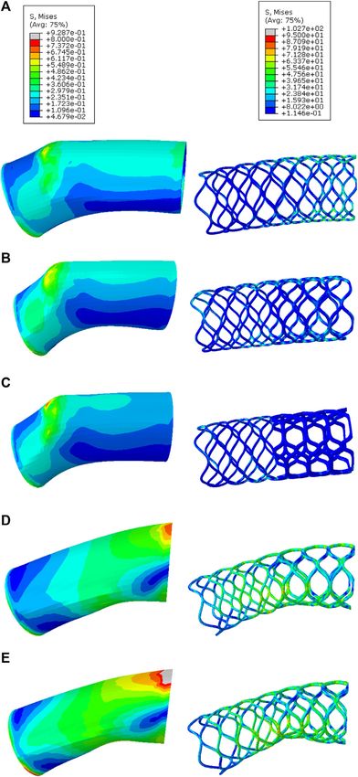
FIGURE 4 | Radial strength test: (A) beginning of the test; (B) step 1: balloon dilation; (C) step 2: balloon contraction. (D) Displacement induced by the outer
cylinder.
buckling that can be interpreted as the stent’s failure (ASTM
F3067-14, 2014).
The more the amount of collapse pressure, the more radial
strength the stent enjoys. Thus, the goal of this optimization is to
increase the collapse pressure. Because the aim of the
optimization is to find the least amount of objective function,
the reverse of collapse pressure is set as the objective function. In
this model, the pressure in each frame is calculated by dividing
the sum of all node forces by the current area of the displacement
supplier. Only one ring of the whole stent is modeled on behalf of
all the rings, in order to decrease the calculation cost. FIGURE 5 | Schematic view of the three-point bending test (Nagler,
Takashima et al. assumed a cylindrical surface as a balloon 2019).
catheter to dilate the stent by applying radial direction
displacement (step 1) and a cylindrical surface as a
displacement supplier (step 3). In their study, the modeling the stent ring was fixed in the axial direction. The interaction
results were validated both qualitatively and quantitatively between the stent and both the balloon and the displacement
(Takashima et al., 2007). Accordingly, in this simulation, the supplier was assumed as isotropic with a friction coefficient of 0.1.
balloon and the displacement supplier were modeled as The balloon and the displacement supplier were both modeled as
deformable cylindrical shells, whose diameter expanded to an isotropic elastic material with extremely high elastic modulus.
3.2 mm and decreased to 2.5 mm, respectively. One end of the
stent ring was fixed in the axial direction, and the other end was Bending Flexibility
free. The assembly model including the stent ring, the balloon, There are different methods to quantify and assess a stent’s
and the displacement supplier is shown in Figure 4. One end of flexibility, among which the three-point bending test is opted
Frontiers in Mechanical Engineering | www.frontiersin.org 5 May 2021 | Volume 7 | Article 689002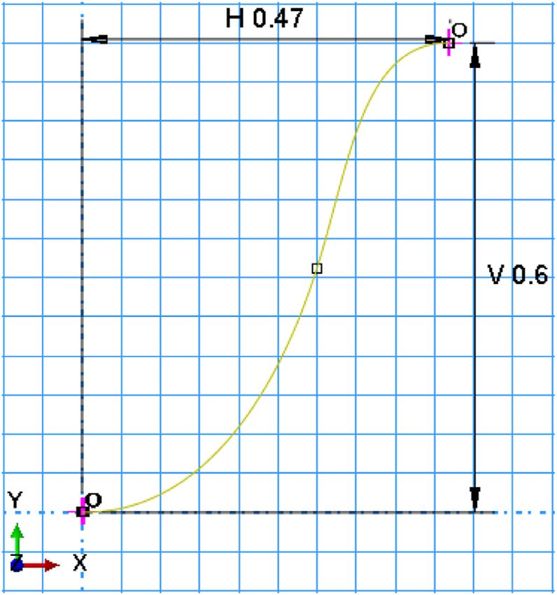
Baradaran et al.                                                                                                                               Stent for Curved Arteries

                                                                                           In the model of three-point bending, two lower static pins and
                                                                                        the upper one that applies load were all modeled as the rigid
                                                                                        cylinders with a diameter of 6.35 mm according to ASTMF2606-
                                                                                        08 (ASTM F2606-08, 2014). As the total length of the stent is
                                                                                        32 mm, the span length of these parts is 11 mm. The model was
                                                                                        symmetric; in order to reduce the calculation cost, half of the
                                                                                        model was simulated. The displacement of the nodes on the plane
                                                                                        passing through the diameter of the stent and parallel to the
                                                                                        bending force (x direction) was set to zero in the z direction
                                                                                        (Figure 6).

                                                                                        Optimization Results
                                                                                        The Pareto optimal solution, resulted from GA multi-objective
                                                                                        optimization, is shown in Figure 7 and Table 2.
 FIGURE 6 | Three-point bending test simulation.

 FIGURE 7 | Pareto Front; vertical axis is the reverse of collapse pressure (1/MPa), horizontal axis is the 3point bending force (N).

in this work. Three-point bending of the stent was simulated                            Post-processing
according to the ASTM standard (ASTM F2606-08, 2014).                                   The interest of the Pareto front approach in this context is, thus,
The schematic of the three-point bending test is shown in                               to allow the designer to choose the appropriate stent design,
Figure 5. Two lower static pins were set in a predefined                                 depending on which criteria to enhance. Here, flexibility is
center–center distance (span length) of 11 mm according to                              preferred in the ends of the stent, while radial stiffness is
the stent’s length, based on ASTMF2606-08 (ASTM F2606-                                  preferred in the middle part. Accordingly, different weights are
08, 2014). The upper pin was located in the middle of the                               assigned to these objectives, in different parts of the stent. Five
span. A downward displacement 1.3 mm of the loading or                                  different sets are defined in Table 3. The fifth design is not defined
upper pin was applied, which forced the tested stent to bend                            by weighting. Here, maximum radial strength is associated with
(Figure 5). This is the displacement both allowed in the                                the middle part, and maximum flexibility is associated with the
ASTM standard and estimated for a vessel with a                                         ends of the stent. These five sets are just the suggestions of the
curvature radius of 10 mm.                                                              authors, while any other weight set based on the operator’s
   The reaction force and displacement of the upper pin were                            diagnosis is applicable to all the Pareto solution points.
stated during simulation, creating a force–deflection curve. The                             For each set and each stent part, weight coefficients are
less the force needed for bending, the more flexibility the stent                        multiplied in the normalized objective functions of the Pareto
benefits. Thus, the optimization goal is to reduce the force needed                      front and summed up together. The point of the minimum result
to bend the stent. The self-contact of the stent ring was defined,                       is implemented for the design. The design parameters are listed in
and the frictionless condition was supposed.                                            Table 4.

Frontiers in Mechanical Engineering | www.frontiersin.org                           6                                              May 2021 | Volume 7 | Article 689002
Baradaran et al. Stent for Curved Arteries
TABLE 2 | Pareto front points—“x” and “y” are the spline middle point coordinates and “th” stands for the thickness.
x (mm) y (mm) th (mm) Three-point 1/Collapse pressureM Pa − 1
bending force (N)
0.24902 0.45 0.2 1.27082 1.18107
0.22218 0.29811 0.19994 1.2393 1.18314
0.23315 0.41127 0.19885 1.21959 1.19756
0.22121 0.29707 0.19902 1.21515 1.19973
0.24769 0.44505 0.19535 1.18171 1.20033
0.24756 0.43727 0.19624 1.15925 1.21217
0.24671 0.44356 0.19431 1.15623 1.2305
0.24482 0.43399 0.19474 1.13119 1.23581
0.21629 0.27754 0.1943 1.11283 1.24993
0.22361 0.29827 0.19424 1.10295 1.25033
0.22132 0.29805 0.19303 1.10063 1.25975
0.21572 0.27894 0.19307 1.07358 1.26118
0.21643 0.2826 0.19219 1.06062 1.26248
0.24222 0.4321 0.18981 1.05511 1.28097
0.22409 0.29863 0.19035 1.03474 1.285
0.23494 0.3982 0.18925 1.03327 1.28572
0.23379 0.41051 0.18872 1.02516 1.28988
0.21656 0.27852 0.1881 1.0142 1.30054
0.21689 0.27204 0.18665 0.98196 1.31657
0.22228 0.29717 0.18655 0.97516 1.32041
0.24496 0.43424 0.18489 0.96208 1.33182
0.2248 0.29834 0.18404 0.94051 1.33866
0.22168 0.29164 0.18372 0.91958 1.3459
0.21542 0.27678 0.18283 0.91411 1.34939
0.21608 0.27052 0.18127 0.8881 1.36076
0.20662 0.29151 0.17953 0.88275 1.38179
0.20967 0.31717 0.1792 0.86532 1.38336
0.23517 0.36517 0.17785 0.85204 1.39307
0.23022 0.37096 0.17828 0.84724 1.39435
0.23431 0.37818 0.17647 0.82446 1.40489
0.20792 0.27674 0.17612 0.81355 1.41198
0.2465 0.43189 0.17578 0.81338 1.42169
0.24373 0.44547 0.17369 0.81293 1.42309
0.21982 0.29857 0.17471 0.7929 1.4266
0.22305 0.29819 0.17497 0.78329 1.42736
0.22119 0.28693 0.17455 0.77684 1.43376
0.24812 0.44329 0.17251 0.77275 1.44171
0.20159 0.27647 0.17268 0.76648 1.44731
0.23055 0.37473 0.17246 0.75852 1.44977
0.24033 0.39583 0.17166 0.75026 1.45235
0.20954 0.30301 0.17158 0.75024 1.46346
0.20965 0.31434 0.17101 0.74082 1.46528
0.24994 0.44985 0.16878 0.71895 1.47101
0.20853 0.2723 0.16913 0.71101 1.47694
0.22646 0.38785 0.16849 0.68692 1.48394
0.22829 0.42146 0.1678 0.64904 1.48547
0.23469 0.40046 0.1642 0.64504 1.52211
0.24135 0.42654 0.16267 0.64017 1.52597
0.23487 0.39948 0.16372 0.63526 1.52843
0.20727 0.26714 0.16291 0.62352 1.53208
0.22261 0.29761 0.163 0.62168 1.53674
0.21595 0.27548 0.16281 0.6189 1.53982
0.23655 0.42833 0.16126 0.61882 1.54595
0.23474 0.39633 0.16135 0.60577 1.54919
0.24504 0.43891 0.1593 0.58587 1.55642
0.23547 0.40228 0.15913 0.58496 1.5715
0.23229 0.34374 0.15935 0.5774 1.57173
0.24518 0.43 0.15893 0.57034 1.57254
0.2245 0.40527 0.15733 0.55792 1.57796
0.2285 0.41181 0.15731 0.5498 1.58699
0.23451 0.36478 0.15626 0.53429 1.5967
0.2292 0.43569 0.1555 0.52506 1.60163
0.22563 0.38449 0.15393 0.52323 1.61323
(Continued on following page)
Frontiers in Mechanical Engineering | www.frontiersin.org 7 May 2021 | Volume 7 | Article 689002Baradaran et al. Stent for Curved Arteries
TABLE 2 | (Continued) Pareto front points—“x” and “y” are the spline middle point coordinates and “th” stands for the thickness.
x (mm) y (mm) th (mm) Three-point 1/Collapse pressureM Pa − 1
bending force (N)
0.23416 0.36713 0.15427 0.52154 1.6177
0.23049 0.35426 0.15334 0.51126 1.62193
0.22308 0.29889 0.15252 0.50055 1.63344
0.22717 0.36363 0.15108 0.49979 1.64283
0.22295 0.29755 0.15165 0.49159 1.64516
0.21478 0.266 0.15145 0.49144 1.64571
0.22554 0.41371 0.15029 0.487 1.64858
0.22237 0.39953 0.14966 0.47668 1.651
0.23852 0.42861 0.14985 0.45159 1.65356
0.24719 0.44379 0.14556 0.40468 1.68723
TABLE 3 | Five sets for objective function weights.
Design no. Flexibility weight for Radial strength weight Flexibility weight for Radial strength weight
the middle part for the middle the ends for the ends
part
1 2 3 3 2
2 1 2 2 1
3 1 4 4 1
4 1 5 5 1
5 Maximum radial strength Maximum flexibility
TABLE 4 | Design sets.
Design no. Design parameters of the middle part Design parameters of the ends
x (mm) y (mm) th (mm) x (mm) y (mm) th (mm)
1 0.24719 0.44379 0.14556 0.24719 0.44379 0.14556
2 0.22829 0.42146 0.1678 0.24719 0.44379 0.14556
3 0.24769 0.44505 0.19535 0.24719 0.44379 0.14556
4 0.22218 0.298111 0.19994 0.24719 0.44379 0.14556
5 0.24902 0.45 0.2 0.24719 0.44379 0.14556
Each of the above stent implementation in a curved vessel was
simulated in ABAQUS/CAE. The artery has the central curvature
radius of 10 mm. Both the artery curvature and the stent structure
are symmetric with respect to the plane passing through the
middle section. In order to reduce the calculation costs, half of the
artery, stent, and balloon was simulated and the symmetry
boundary condition was applied.
The balloon was simulated as a cylindrical surface with the
outer diameter of 1.3 mm. In the first step, the artery was avoided
from dislocation by fixing the nodes on the symmetry plane. The
FIGURE 8 | Fillet at the intersection of middle and end parts of the stent.
assembly of the stent and the balloon was pushed to the vessel by a
displacement. After the stent and the balloon completely reached
the targeted lesion site, the balloon dilated the artery inner
The outer diameter of the stent is equal all over the stent, while diameter to 3.2 mm. Thus, the stent was expanded to open the
the thickness is different from middle parts to end parts. In order closed lumen. Then, the balloon shrinks to its initial diameter,
to avoid sharp edges caused by thickness difference in the letting the stent spring back. A friction coefficient of 0.1 was
intersection of these two parts, round fillets are applied prescribed among all contact surfaces. The artery and plaque were
(Figure 8). The thickness difference is too small to cause meshed with about 4,170 quadratic tetrahedral elements of type
significant changes in the blood flow. C3D10. The stent was also discretized into about 34,660 quadratic
Frontiers in Mechanical Engineering | www.frontiersin.org 8 May 2021 | Volume 7 | Article 689002Baradaran et al. Stent for Curved Arteries
TABLE 5 | Material coefficients of arterial tissue layers, plaque tissue, and balloon The artery straightening has occurred less in the fourth and the
(Karimi et al., 2014).
fifth design. Thus, it can be discussed that the comfortability of
Arterial tissue μ1 (MPa) μ2 μ3 α1 α2 α3 the stent to the artery curvature is easier when the radial strength
layers (Ogden) is considerably different in the middle and end parts of the stent.
In these five designs, as the mid-part radial strength weight
Intima −7.04 4.23 2.85 24.48 25.00 −7.04
Media −1.23 0.88 0.45 16.59 16.65 −1.23 increases, the stress gets distributed more evenly through the
Adventitia −1.28 0.85 0.44 24.63 25.00 −1.28 stent, which reduces the danger of stent breaking and restenosis.
Plaque (Mooney–Rivlin) C10 (MPa) C01 C20 C11 C02 For curved arteries exposed to several external forces, the last two
Cellular plaque −0.80 0.83 0 1.15 0 designs are suggested, since the risk of breaking gets reduced.
TABLE 6 | Maximum stress in the artery wall and the stent designs.
Design1 Design2 Design3 Design4 Design5
Maximum stress in artery wall (MPa) 0.621 0.692 0.663 0.714 0.9278
Maximum stress in stent (MPa) 64.7 57.4 30.5 85.9 102.7
tetrahedral elements of type C3D10, and the balloon was The thickness and strut curvature of the end part are the same
discretized into 988 elements. In the simulation, all the nodes for all designs, but stress amounts are different in these parts. This
on the symmetry plane passing through the length of the stent difference originates from the difference in the middle part.
were close in the direction orthogonal to the plane. Indeed, the geometric parameters in the middle part affect the
The material properties of arterial tissue layers and plaque are mechanical behavior of the whole stent. Despite having the
stated in Table 5 (Karimi et al., 2014). Each layer was modeled as mechanical properties of each part, the mechanical
an incompressible isotropic hyperelastic material. The artery performance of the whole stent cannot be exactly predicted.
thickness was assumed to be 0.5 mm with a thickness ratio for But, by having the mechanical performance of these five
Int:Med:Adv of 13:32:55 (Schulze-Bauer et al., 2003). designs, the mechanical performance of other combinations of
the Pareto solution points can be almost estimated.
RESULTS AND DISCUSSION Radial Recoil
The radial recoil ratio after the expanding process, an important
Stress Distribution index characterizing the stent’s strength, was calculated in stent
Despite considering different objective function weights, design implementation steps. It is defined by the profile changes between
parameters were the same for the end part of the stent in all two stages: In the first stage, the stent was expanded to a required
designs (Tables 3, 4). In this part, flexibility was weighted 1.5, 2, 4, inner diameter, 3.2 mm. In the second stage, the balloon shrinked
and 5 times more than radial strength. In the middle part of the to its initial diameter and the stent sprang back after expanding.
stent, radial strength was weighted more than flexibility. By The formula is stated as follows (Venkatraman et al., 2008):
increasing the radial strength weight, thickness increased Radial Recoil
relatively (Table 4). Inner Diameterafter expansion − Inner Diameterafter spring back
We considered flexibility as an objective that allows the stent . (1)
Inner Diameterafter expansion
to take the curvature of the stent with lower force. The force
deforming the stent causes stress distribution in the stent and the The radial recoil ratio after expanding determines the over-
artery. In this regard, von Mises stress distribution after the first increment in the outer diameter of the stent applied in a
step of simulation is studied. The von Mises stress contour of the particular vessel environment. Too much radial recoil causes
artery and the stent is shown in Figure 9. large over-expanding and great strain generation in the arteries,
It can be seen that, by changing the radial strength and leading to a great risk of mechanical injury and follow-up
flexibility along the stent, the stress distribution changes in the inflammation (Wang et al., 2017). Radial recoil ratios of the
artery wall (Figure 9). In the first three designs, the maximum expanded stent in simulations were calculated at the middle of the
stress is observed in the end part of the artery, while in the stent length (Table 7). The results show that radial recoil
fourth and the fifth design, greater stresses are observed in the decreases by radial strength decrease. It can also be interpreted
middle parts of the arteries. It is important to note that the that radial recoil has a direct relationship with stent thickness
maximum stress in the artery by the first three stents is less (Tables 4, 7).
than the maximum stress by the last two designs (see Table 6). Since its too high value can cause blockage and death, radial
Since the artery stress instigates inflammation and restenosis, recoil is the most important criterion for the success of a stent
the first three designs are suitable for tortuous and highly implementation. Thus, in addition to stress distribution and
curved arteries. maximum stress, radial recoil should be considered when
Frontiers in Mechanical Engineering | www.frontiersin.org 9 May 2021 | Volume 7 | Article 689002Baradaran et al. Stent for Curved Arteries
physicians should be provided with a variety of stents with
different characteristics to choose on a case-by-case basis. In
other words, there is no ideal stent for all the arteries. Some
arteries should be dilated by flexible stents because of their very
short curvature radius or stiff structure, while other arteries
should be dilated by radially strong stents because of their stiff
plaque or presence of several dynamic loads in their location.
Some arteries need both flexibility and radial strength at a
moderate amount according to stenosis. Accordingly, in this
work, a variety of optimized stents have been provided.
Among these stents, five design sets, with different flexibilities
and radial strength weights, have been simulated to be studied
from a mechanical performance point of view.
All in all, one can choose a stent with a definite amount of
radial strength considering a limit for flexibility, and vice versa. In
order to utilize this design efficiently, physicians should provide a
CT angiogram to assess the curvature and the plaque thickness.
Considering the exposure level of the artery to external forces and
its stiffness, physicians should give weight to each of the flexibility
and radial strength for each section of the stent. Weight
coefficients should be multiplied in the normalized objective
functions of the Pareto front (Table 2) and get summed up
together. The point of the minimum result should be
implemented for the design. It is even possible to consider
three different weight coefficient sets for the distal, middle,
and proximal sections of the stent according to the geometry
of the artery.
CONCLUSION
In this study, using the finite element method, a stent was
designed to be implanted in a curved vessel. Rather than
searching a single optimal design, the use of GA multi-
objective optimization addresses the flexibility and radial
strength variation in a stent. The resulting Pareto set forms
the basis of a design guide from which physicians can select
an appropriate flexible–radially strong design, depending on the
characteristics of a particular patient’s diseased curved artery. The
optimization methodology has proved that this technique can
serve as a stent strut design tool. An optimization process seems
to bring a real improvement compared to a less systematic
approach that is currently used for the design of stents.
Since a range of Pareto optimal design parameter values were
obtained, which can be used in clinical design guides so as to
accommodate variations observed across different patients,
polylactic acid was chosen as the material for the stent. In this
FIGURE 9 | von Mises stress (MPa) distribution in the artery wall (left)
and stent (right): (A) Design1, (B) Design2, (C) Design3, (D) Design4, and (E)
Design5, after dilating the stent in the artery.
TABLE 7 | Radial recoil ratios of the expanded stent in simulations.
Design no. Radial recoil (%)
opting for the right stent for a curved artery. Arteries with stiff
plaque or those exposed to numeric loads should be healed with Design1 4.687
Design2 4.282
stents enjoying less rate of recoil. Design3 4.002
The artery structure and properties differ person to person Design4 3.926
depending on age, gender, lifestyle, diet, and so forth. This is why Design5 3.844
Frontiers in Mechanical Engineering | www.frontiersin.org 10 May 2021 | Volume 7 | Article 689002Baradaran et al. Stent for Curved Arteries
way, the operator can opt for a desired stent from the Pareto front This modeling can also be used to simulate stents with other
and produce or order it easily. The operator has also the option of elastic–plastic materials. Furthermore, it is applicable in other
joining two or more designs from the Pareto front, in order to stent applications such as biliary stents, to simple plastic stents
have desired performance along the stent. used to allow the flow of urine between the kidney and the
In this work, radial strength and flexibility are differently bladder.
preferred in the middle section and extremes of the stent. Five There were some limitations in this work. Struts were
different objective weight sets are allocated to the Pareto set, directly interconnected with each other, while they could be
leading to five different stent designs, in the post-processing interconnected by links as a common way of increasing
procedure. Using the finite element method, these stents are flexibility. The optimization procedure was time-
implemented in a curved vessel, and their stress distribution, consuming, which could take shorter time using other
maximum stress, and radial recoil are measured. The designs mathematical methods such as the Taguchi or neural
whose middle and end parts are more flexible are suitable for network. In future works, other optimization variables
tortuous and highly curved arteries, since the maximum stress such as the number of struts can be optimized. The shape
they exert to the artery wall is reduced. The designs with higher difference can be applied to more than two parts of the stent.
radial strength in the middle part are suggested for curved arteries Biodegradable alloys might be used as the material of
exposed to several external forces, since the stress is distributed the stent.
more evenly and, thus, the risk of breaking gets reduced.
One of this work’s main contributions is the use of spline
curvature point coordinates and stent thickness to considerably DATA AVAILABILITY STATEMENT
expand the range of stent shapes that a single geometric modeler
can produce. We proposed a method to use spline point The original contributions presented in this study are included in
coordinates and strut thickness as optimization design the article/Supplementary Material. Further inquiries can be
variables, achieving remarkable geometric variation compared directed to the corresponding author.
to previous stent parameterizations. This spread variation ensures
we are seeking a broad geometric design space during
optimization. AUTHOR CONTRIBUTIONS
The stenting modeling has revealed useful results that are hard
or impossible to be caught by experimental approaches. The YB and MK designed the model and the computational
applicability of this modeling is not limited to von Mises stress framework and analyzed the data. MOB and MAB were
and radial recoil measurement. There are other mechanical involved in planning and supervised the work. SH and MOK
objectives that can be assessed through this modeling aided in interpreting the results and worked on the manuscript.
procedure, including principal stress and strain in both the All authors contributed to manuscript writing and read and
artery and the stent, stent shortening, and energy magnitudes. approved the submitted version.
Fathi, P., Capron, G., Tripathi, I., Misra, S., Ostadhossein, F., Selmic, L., et al.
REFERENCES (2020). Computed Tomography-Guided Additive Manufacturing of
Personalized Absorbable Gastrointestinal Stents for Intestinal Fistulae and
Alaimo, G., Auricchio, F., Conti, M., and Zingales, M. (2017). Multi-Objective Perforations. Biomaterials 228, 119542. doi:10.1016/j.biomaterials.2019.119542
Optimization of Nitinol Stent Design. Med. Eng. Phys. 47, 13–24. doi:10.1016/j. Gordon, W. J., and Riesenfeld, R. F. (1974). “Computer Aided Geometric Design,”
medengphy.2017.06.026 in Computer Aided Geometric Design. Editors R. Barnhill and R. F. Riesenfeld
Bezhaev, A. Y., and Vasilenko, V. A. (2001). Variational Theory of Splines. New (New York, NY: Academic Press), 95–126.
York: Springer. Guerra, A., Roca, A., and de Ciurana, J. (2017). A Novel 3D Additive
Chen, C., Chen, J., Wu, W., Shi, Y., Jin, L., Petrini, L., et al. (2019). In vivo and Manufacturing Machine to Biodegradable Stents. Procedia Manufact. 13,
in vitro Evaluation of a Biodegradable Magnesium Vascular Stent Designed by 718–723. doi:10.1016/j.promfg.2017.09.118
Shape Optimization Strategy. Biomaterials 221, 119414. doi:10.1016/j. Hopkinson, N., Hague, R., and Dickens, P. (2006). Rapid Manufacturing: An
biomaterials.2019.119414 Industrial Revolution for the Digital Age. Chichister, United Kingdom: John
Chung, M., Radacsi, N., Robert, C., McCarthy, E. D., Callanan, A., Conlisk, N., et al. Wiley & Sons.
(2018). On the Optimization of Low-Cost FDM 3D Printers for Accurate Hua, R., Tian, Y., Cheng, J., Wu, G., Jiang, W., Ni, Z., et al. (2020). The Effect of
Replication of Patient-Specific Abdominal Aortic Aneurysm Geometry. 3D Intrinsic Characteristics on Mechanical Properties of Poly (L-Lactic Acid)
Print. Med. 4 (1), 1–10. doi:10.1186/s41205-017-0023-2 Bioresorbable Vascular Stents. Med. Eng. Phys. 81, 118–124. doi:10.1016/j.
Colpani, A., Fiorentino, A., and Ceretti, E. (2020). Design and Fabrication of medengphy.2020.04.006
Customized Tracheal Stents by Additive Manufacturing. Procedia Manufact. Iqbal, J., Serruys, P. W., Silber, S., Kelbaek, H., Richardt, G., Morel, M-A., et al.
47, 1029–1035. doi:10.1016/j.promfg.2020.04.318 (2015). Comparison of Zotarolimus- and Everolimus-Eluting Coronary Stents:
Demir, A. G., and Previtali, B. (2017). Additive Manufacturing of Cardiovascular Final 5-Year Report of the RESOLUTE All-Comers Trial. Circ. Cardiovasc.
CoCr Stents by Selective Laser Melting. Mater. Des. 119, 338–350. doi:10.1016/j. Interv. 8 (6), e002230. doi:10.1161/circinterventions.114.002230
matdes.2017.01.091 Karimi, A., Navidbakhsh, M., Yamada, H., and Razaghi, R. (2014). A Nonlinear
Ebrahimi, N., Claus, B., Lee, C. Y., Biondi, A., and Benndorf, G. (2007). Stent Finite Element Simulation of Balloon Expandable Stent for Assessment of
Conformity in Curved Vascular Models with Simulated Aneurysm Necks Using Plaque Vulnerability Inside a Stenotic Artery. Med. Biol. Eng. Comput. 52 (7),
Flat-Panel CT: An In Vitro Study. AJNR Am. J. Neuroradiol 28 (5), 823–829. 589–599. doi:10.1007/s11517-014-1163-9
Frontiers in Mechanical Engineering | www.frontiersin.org 11 May 2021 | Volume 7 | Article 689002Baradaran et al. Stent for Curved Arteries
Kasiri, S., and Kelly, D. J. (2011). An Argument for the Use of Multiple Segment Tabriz, A. G., Douroumis, D., Okereke, M., and Khalaj, R. (2019). “3D Printing of
Stents in Curved Arteries. J. Biomech. Eng. 133 (8), 084501. doi:10.1115/1. Bioabsrorbable Polymeric Stents by Fused Deposition Modeling (FDM),”in
4004863 ICS3M 2019: International Conference on Stents Materials, Mechanics and
Li, H., Liu, T., Wang, M., Zhao, D., Qiao, A., Wang, X., et al. (2017). Design Manufacturing, London, United Kingdom, July 15–17, 2019.
Optimization of Stent and its Dilatation Balloon Using Kriging Surrogate Takashima, K., Kitou, T., Mori, K., and Ikeuchi, K. (2007). Simulation and
Model. Biomed. Eng. Online 16 (1), 1–17. doi:10.1186/s12938-016-0307-6 Experimental Observation of Contact Conditions Between Stents and
Mehne, S. H. H., and Mirjalili, S. (2020). “Moth-Flame Optimization Algorithm: Artery Models. Med. Eng. Phys. 29 (3), 326–335. doi:10.1016/j.
Theory, Literature Review, and Application in Optimal Nonlinear Feedback medengphy.2006.04.003
Control Design,” in Nature-Inspired Optimizers: Studies in Computational Tambaca, J., Canic, S., Kosor, M., Fish, R. D., and Paniagua, D. (2011). Mechanical
Intelligence. Editors S. Mirjalili, J. Song Dong, and A. Lewis (Basel, Behavior of Fully Expanded Commercially Available Endovascular Coronary
Switzerland: Springer, Cham), 811, 143–166. Stents. Tex. Heart Inst. J. 38 (5), 491–501.
Mirjalili, S., Mirjalili, S. M., Saremi, S., and Mirjalili, S. (2020a). “Whale Tomita, H., Higaki, T., Kobayashi, T., Fujii, T., and Fujimoto, K. (2015). Stenting
Optimization Algorithm: Theory, Literature Review, and Application in for Curved Lesions Using a Novel Curved Balloon: Preliminary Experimental
Designing Photonic Crystal Filters,” in Nature-Inspired Optimizers: Studies Study. J. Cardiol. 66 (2), 120–124. doi:10.1016/j.jjcc.2014.10.009
in Computational Intelligence. Editors S. Mirjalili, J. Song Dong, and A. Lewis Torki, M. M., Hassanajili, S., and Jalisi, M. M. (2020). Design Optimizations of PLA
(Basel, Switzerland: Springer, Cham), 811, 219–238. Stent Structure by FEM and Investigating its Function in a Simulated Plaque
Mirjalili, S., Song Dong, J., Lewis, A., and Sadiq, A. S. (2020b). “Particle Swarm Artery. Math. Comput. Simul. 169, 103–116. doi:10.1016/j.matcom.2019.09.011
Optimization: Theory, Literature Review, and Application in Airfoil Design,” in Venkatraman, S., Boey, F., and Lao, L. L. (2008). Implanted Cardiovascular
Nature-Inspired Optimizers: Studies in Computational Intelligence. Editors Polymers: Natural, Synthetic and Bio-Inspired. Prog. Polym. Sci. 33 (9),
S. Mirjalili, J. Song Dong, and A. Lewis (Basel, Switzerland: Springer, 853–874. doi:10.1016/j.progpolymsci.2008.07.001
Cham), 811, 167–184. doi:10.1007/978-3-030-12127-3_10 Wang, Q., Fang, G., Zhao, Y., Wang, G., and Cai, T. (2017). Computational and
Mortier, P., Holzapfel, G. A., De Beule, M., Van Loo, D., Taeymans, Y., Segers, P., Experimental Investigation into Mechanical Performances of Poly-L-Lactide
et al. (2010). A Novel Simulation Strategy for Stent Insertion and Deployment Acid (PLLA) Coronary Stents. J. Mech. Behav. Biomed. Mater. 65, 415–427.
in Curved Coronary Bifurcations: Comparison of Three Drug-Eluting Stents. doi:10.1016/j.jmbbm.2016.08.033
Ann. Biomed. Eng. 38 (1), 88–99. doi:10.1007/s10439-009-9836-5 Wei, L., Leo, H. L., Chen, Q., and Li, Z. (2019). Structural and Hemodynamic
Nagler, J. (2019). Failure Mechanics of Multi Materials Laminated Systems Review Analyses of Different Stent Structures in Curved and Stenotic Coronary Artery.
Analysis-Based Project. Turin: School of Mechanical Engineering, University of Front. Bioeng. Biotechnol. 7, 366. doi:10.3389/fbioe.2019.00366
Tel Aviv. Wu, W., Petrini, L., Gastaldi, D., Villa, T., Vedani, M., Lesma, E., et al. (2010). Finite
Pache, J., Kastrati, A., Mehilli, J., Schühlen, H., Dotzer, F., Hausleiter, J., et al. Element Shape Optimization for Biodegradable Magnesium Alloy Stents. Ann.
(2003). Intracoronary Stenting and Angiographic Results: Strut Thickness Biomed. Eng. 38 (9), 2829–2840. doi:10.1007/s10439-010-0057-8
Effect on Restenosis Outcome (ISAR-STEREO-2) Trial. J. Am. Coll. Cardiol. Wu, W., Wang, W.-Q., Yang, D.-Z., and Qi, M. (2007). Stent Expansion in Curved
41 (8), 1283–1288. doi:10.1016/s0735-1097(03)00119-0 Vessel and Their Interactions: A Finite Element Analysis. J. Biomech. 40 (11),
Pant, S., Bressloff, N. W., and Limbert, G. (2012). Geometry Parameterization and 2580–2585. doi:10.1016/j.jbiomech.2006.11.009
Multidisciplinary Constrained Optimization of Coronary Stents. Biomech. Zhao, S., Lin, S., and Gu, L. (2014). “Stent Expansion in Curved Vessel and Their
Model. Mechanobiol. 11 (1–2), 61–82. doi:10.1007/s10237-011-0293-3 Interactions: An In Vitro Study,” in Proceedings of the ASME 2014
Perrin, D., Demanget, N., Badel, P., Avril, S., Orgéas, L., Geindreau, C., et al. (2015). International Mechanical Engineering Congress and Exposition, Montreal,
Deployment of Stent Grafts in Curved Aneurysmal Arteries: Toward a Canada, November 14–20, 2014 (New York, NY: American Society of
Predictive Numerical Tool. Int. J. Numer. Methods Biomed. Eng. 31 (1), Mechanical Engineers Digital Collection).
e02698. doi:10.1002/cnm.2698
Saito, N., Mori, Y., and Komatsu, T. (2020). Influence of Stent Flexibility on Artery Conflict of Interest: The authors declare that the research was conducted in the
Wall Stress and Wall Shear Stress in Bifurcation Lesions. Med. Devices (Auckl). absence of any commercial or financial relationships that could be construed as a
13, 365–375. doi:10.2147/MDER.S275883 potential conflict of interest.
Santos, J. D., Haig, C., and Schwartz, L. B. (2020). Radially Rigid and Longitudinally
Flexible Multi-Element Intravascular Stent. Turin: Google Patents. Copyright © 2021 Baradaran, Baghani, Kazempour, Hosseini, Karimpour and
Schulze-Bauer, C. A. J., Mörth, C., and Holzapfel, G. A. (2003). Passive Biaxial Baniassadi. This is an open-access article distributed under the terms of the Creative
Mechanical Response of Aged Human Iliac Arteries. J. Biomech. Eng. 125 (3), Commons Attribution License (CC BY). The use, distribution or reproduction in
395–406. doi:10.1115/1.1574331 other forums is permitted, provided the original author(s) and the copyright owner(s)
Shen, X., Jiang, J. B., Zhu, H. F., Deng, Y. Q., and Ji, S. (2020). Numerical are credited and that the original publication in this journal is cited, in accordance
Investigation of the Flexibility of a New Self-Expandable Tapered Stent. with accepted academic practice. No use, distribution or reproduction is permitted
J. Mech. 36 (4), 577–584. doi:10.1017/jmech.2020.11 which does not comply with these terms.
Frontiers in Mechanical Engineering | www.frontiersin.org 12 May 2021 | Volume 7 | Article 689002You can also read