Operating Instructions - Radar sensor for continuous level measurement in plastic vessels - Autarkic device ...
←
→
Page content transcription
If your browser does not render page correctly, please read the page content below
Operating Instructions
Radar sensor for continuous level
measurement in plastic vessels

VEGAPULS Air 23
Autarkic device with measured value trans-
mission via radio technology

Document ID: 64314
Contents

Contents
1   About this document................................................................................................................ 4
    1.1 Function............................................................................................................................ 4
    1.2 Target group...................................................................................................................... 4
    1.3 Symbols used................................................................................................................... 4
2   For your safety.......................................................................................................................... 5
    2.1 Authorised personnel........................................................................................................ 5
    2.2 Appropriate use................................................................................................................. 5
    2.3 Warning about incorrect use.............................................................................................. 5
    2.4 General safety instructions................................................................................................ 5
    2.5 Lithium cells...................................................................................................................... 6
    2.6 Country of use................................................................................................................... 6
3   Product description.................................................................................................................. 7
    3.1 Configuration..................................................................................................................... 7
    3.2 Principle of operation........................................................................................................ 8
    3.3 Adjustment........................................................................................................................ 9
    3.4 Packaging, transport and storage...................................................................................... 9
4   Mounting.................................................................................................................................. 10
    4.1 General instructions........................................................................................................ 10
    4.2 Mounting instructions...................................................................................................... 10
    4.3 Mounting preparations.................................................................................................... 11
    4.4 Installation procedure...................................................................................................... 12
    4.5 Transportation lock after mounting.................................................................................. 13
5   Setup........................................................................................................................................ 14

6   Diagnostics and servicing..................................................................................................... 18
    6.1 Maintenance................................................................................................................... 18
    6.2 Rectify faults.................................................................................................................... 18
    6.3 How to proceed if a repair is necessary........................................................................... 19
7   Removal with glue connection.............................................................................................. 20
    7.1 Dismounting instructions................................................................................................. 20
    7.2 Dismounting steps mounting ring.................................................................................... 20
    7.3 Disposal.......................................................................................................................... 21
8   Certificates and approvals..................................................................................................... 22
    8.1 Radio licenses................................................................................................................. 22
    8.2 EU conformity.................................................................................................................. 22
    8.3 Environment management system.................................................................................. 22
9   Supplement............................................................................................................................. 23
    9.1 Technical data................................................................................................................. 23
    9.2 Radio networks LTE-M and NB-IoT................................................................................. 26
    9.3 Radio networks LoRaWAN - Data transmission.............................................................. 26
    9.4 Dimensions..................................................................................................................... 29
                                                                                                                                                       64314-EN-210322

    9.5 Industrial property rights.................................................................................................. 30
    9.6 Licensing information for open source software.............................................................. 30
    9.7 Trademark....................................................................................................................... 30

2                          VEGAPULS Air 23 • Autarkic device with measured value transmission via radio technology
Contents
64314-EN-210322
Safety instructions for Ex areas
Take note of the Ex specific safety instructions for Ex applications.
These instructions are attached as documents to each instrument
with Ex approval and are part of the operating instructions.
Editing status: 2021-03-17
VEGAPULS Air 23 • Autarkic device with measured value transmission via radio technology 31 About this document
1 About this document
1.1 Function
This instruction provides all the information you need for mounting,
connection and setup as well as important instructions for mainte-
nance, fault rectification, the exchange of parts and the safety of the
user. Please read this information before putting the instrument into
operation and keep this manual accessible in the immediate vicinity
of the device.
1.2 Target group
This operating instructions manual is directed to trained personnel.
The contents of this manual must be made available to the qualified
personnel and implemented.
1.3 Symbols used
Document ID
This symbol on the front page of this instruction refers to the Docu-
ment ID. By entering the Document ID on www.vega.com you will
reach the document download.
Information, note, tip: This symbol indicates helpful additional infor-
mation and tips for successful work.
Note: This symbol indicates notes to prevent failures, malfunctions,
damage to devices or plants.
Caution: Non-observance of the information marked with this symbol
may result in personal injury.
Warning: Non-observance of the information marked with this symbol
may result in serious or fatal personal injury.
Danger: Non-observance of the information marked with this symbol
results in serious or fatal personal injury.
Ex applications
This symbol indicates special instructions for Ex applications.
• List
The dot set in front indicates a list with no implied sequence.
1 Sequence of actions
Numbers set in front indicate successive steps in a procedure.
Battery disposal
This symbol indicates special information about the disposal of bat-
teries and accumulators.
64314-EN-210322
4 VEGAPULS Air 23 • Autarkic device with measured value transmission via radio technology2 For your safety
2 For your safety
2.1 Authorised personnel
All operations described in this documentation must be carried out
only by trained, qualified personnel authorised by the plant operator.
During work on and with the device, the required personal protective
equipment must always be worn.
2.2 Appropriate use
The VEGAPULS Air 23 is an autarkic sensor for continuous level
measurement in plastic vessels.
You can find detailed information about the area of application in
chapter " Product description".
Operational reliability is ensured only if the instrument is properly
used according to the specifications in the operating instructions
manual as well as possible supplementary instructions.
2.3 Warning about incorrect use
Inappropriate or incorrect use of this product can give rise to applica-
tion-specific hazards, e.g. vessel overfill through incorrect mounting
or adjustment. Damage to property and persons or environmental
contamination can result. Also, the protective characteristics of the
instrument can be impaired.
2.4 General safety instructions
This is a state-of-the-art instrument complying with all prevailing
regulations and directives. The instrument must only be operated in a
technically flawless and reliable condition. The operator is responsi-
ble for the trouble-free operation of the instrument. When measuring
aggressive or corrosive media that can cause a dangerous situation
if the instrument malfunctions, the operator has to implement suitable
measures to make sure the instrument is functioning properly.
The safety instructions in this operating instructions manual, the na-
tional installation standards as well as the valid safety regulations and
accident prevention rules must be observed by the user.
For safety and warranty reasons, any invasive work on the device
beyond that described in the operating instructions manual may be
carried out only by personnel authorised by the manufacturer. Arbi-
trary conversions or modifications are explicitly forbidden. For safety
reasons, only the accessory specified by the manufacturer must be
used.
To avoid any danger, the safety approval markings and safety tips on
the device must also be observed.
64314-EN-210322
The low transmitting power of the radar sensor as well as the inte-
grated LTE-NB1, LTE-CAT-M1 or LoRa radio module is far below
the internationally approved limits. No health impairments are to be
expected with intended use. The band range of the transmission
frequency can be found in chapter " Technical data".
VEGAPULS Air 23 • Autarkic device with measured value transmission via radio technology 52 For your safety
2.5 Lithium cells
The power supply of the device is provided by integrated lithium cells
in the housing. If the device is used as intended with the lid closed
within the temperatures and pressures specified in the technical data,
it is thus adequately protected.
Note:
Please observe the specific safety instructions in the scope of deliv-
ery of the device.
2.6 Country of use
Country-specific settings for transmission into the mobile radio
network or LoRaWan are defined by selecting the country of use. It is
absolutely essential to do this during the job-specific device configu-
ration.
Caution:
Operation of the device with a false country of use selection can
lead to malfunctions and constitutes a violation of the radio licensing
regulations of the respective country.
64314-EN-210322
6 VEGAPULS Air 23 • Autarkic device with measured value transmission via radio technology3 Product description
3 Product description
3.1 Configuration
Scope of delivery The scope of delivery encompasses:
• Radar sensor
• Integrated identification card for LTE (eSIM) (optional)
• Magnet for activation
• Mounting ring with glued surface, cleaning cloth (version for glued
connection)
• Tension belt (for version with flexible changeable holder)
• Information sheet " Documents and software" with:
–– Instrument serial number
–– QR code with link for direct scanning
• Information sheet " PINs and Codes" with:
–– Identifier for LoRaWAN network (Device EUI, Application EUI,
App Key)
The further scope of delivery encompasses:
• Documentation
–– Safety instructions for lithium metal cell
–– If necessary, further certificates
Note:
Optional instrument features are also described in this operating
instructions manual. The respective scope of delivery results from the
order specification.
Scope of this operating This operating instructions manual applies to the following instrument
instructions versions:
• Hardware version from 1.0.0
• Software version from 1.0.0
Versions The radar sensor VEGAPULS Air 23 is available with different mount-
ing techniques:
• Adhesive joint (antenna side)
• Flexibly exchangeable holder
• Ceil mounting
64314-EN-210322
VEGAPULS Air 23 • Autarkic device with measured value transmission via radio technology 73 Product description
Constituent parts
5
4
3
2
1
Fig. 1: Components of the VEGAPULS Air 23 sensor (example version for
adhesive joint)
1 Radar antenna
2 Unscrewable mounting ring with glue surface
3 Eyelets for transport lock
4 Housing lid
5 Contact surface for activation by NFC or magnet
Type label The type plate contains the most important data for identification and
use of the device. This is located on the sensor housing.
LTE-NB-IoT, LTE-Cat-M1, LoRa Date:
B3 B8 B20 www.vega.com
EU868 IP66/69
VEGAPULS Air 23 1,2m PVDF
Made in Germany
AR - 222 22C s/n 49663242
D-77761 Schiltach
Device EUI E8E8B7000040BA20
1 2 3 4 5
Fig. 2: Layout of the type label (example)
1 Order number
2 Wireless signal outputs, frequency bands
3 Device EUI LoRa
4 Technical data
5 QR code for device documentation
3.2 Principle of operation
Application area VEGAPULS Air 23 is a radar sensor for continuous level measure-
ment of plastic vessels, e.g. IBC containers. 1)
The device is suitable for almost all liquids.
Depending on the version, it is mounted to the vessel or to the ceiling
by means of:
• Glue surface on the bottom side of the sensor (vessel mounting)
• Tension belt (vessel mounting)
• Mounting brackets on the housing (ceiling mounting)
Functional principle The instrument emits a continuous, frequency-modulated radar signal
through its antenna. The emitted signal is reflected by the medium
and received by the antenna as an echo with modified frequency. The
64314-EN-210322
frequency change is proportional to the distance and is converted into
the level.
The measurement is made through the closed plastic ceiling of the
vessel.
1)
IBC = Intermediate Bulk Container
8 VEGAPULS Air 23 • Autarkic device with measured value transmission via radio technology3 Product description
Measured value transmis- Depending on the availability of the radio networks, the device trans-
sion mits its measured values wirelessly to an LTE-M (LTE-CAT-M1) or NB-
IoT (LTE-CAT-NB1) mobile radio or a plant-side LoRaWAN network.
The transmission or evaluation is carried out via an Asset Manage-
ment System, e.g. VEGA Inventory System.
Voltage supply The device is supplied with energy by non-exchangeable primary
cells. The lithium cell used for this purpose is a compact storage
device with high cell voltage and capacity for a long service life.
3.3 Adjustment
The device is activated contactlessly from outside:
• Via magnet
• By NFC technology via smartphone/tablet with VEGA Tools app
There are no additional adjustment options.
3.4 Packaging, transport and storage
Packaging Your instrument was protected by packaging during transport. Its
capacity to handle normal loads during transport is assured by a test
based on ISO 4180.
The packaging consists of environment-friendly, recyclable card-
board. For special versions, PE foam or PE foil is also used. Dispose
of the packaging material via specialised recycling companies.
Transport Transport must be carried out in due consideration of the notes on the
transport packaging. Nonobservance of these instructions can cause
damage to the device.
Transport inspection The delivery must be checked for completeness and possible transit
damage immediately at receipt. Ascertained transit damage or con-
cealed defects must be appropriately dealt with.
Storage Up to the time of installation, the packages must be left closed and
stored according to the orientation and storage markings on the
outside.
Unless otherwise indicated, the packages must be stored only under
the following conditions:
• Not in the open
• Dry and dust free
• Not exposed to corrosive media
• Protected against solar radiation
• Avoiding mechanical shock and vibration
Storage and transport • Storage and transport temperature see chapter " Supplement -
temperature Technical data - Ambient conditions"
64314-EN-210322
• Relative humidity 20 … 85 %
VEGAPULS Air 23 • Autarkic device with measured value transmission via radio technology 94 Mounting
4 Mounting
4.1 General instructions
Ambient conditions The instrument is suitable for standard and extended ambient condi-
tions acc. to DIN/EN/IEC/ANSI/ISA/UL/CSA 61010-1. It can be used
indoors as well as outdoors.
Process conditions Note:
For safety reasons, the instrument must only be operated within the
permissible process conditions. You can find detailed information on
the process conditions in chapter " Technical data" of the operating
instructions or on the type label.
Hence make sure before mounting that all parts of the instrument ex-
posed to the process are suitable for the existing process conditions.
Transport, alignment, The device measures the level only when aligned downwards.
position detection To ensure this, the device has a GPS position sensor and an inde-
pendent position sensor.
Note:
If the container is aligned horizontally (e.g. tilted during transport of a
mobile container) no measurement is taken.
4.2 Mounting instructions
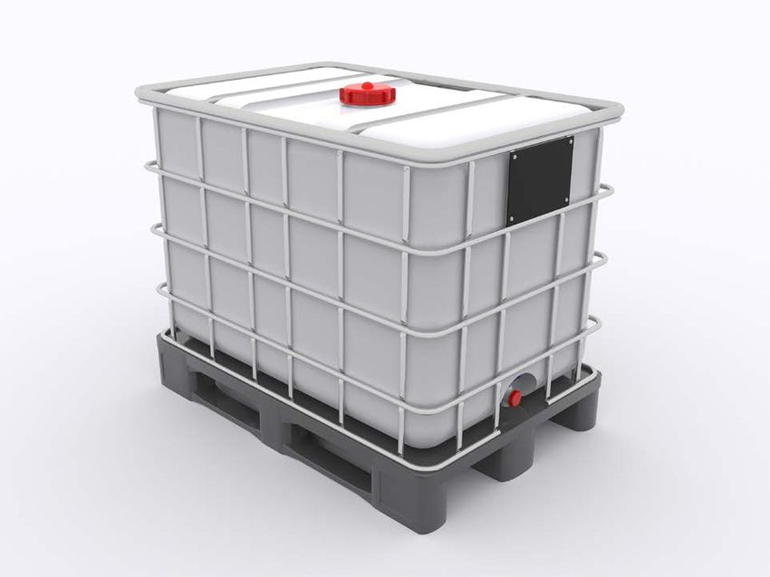
Container requirements The containers can be commercially available combination IBC con-
tainers with a nominal volume of e.g. 1000 l. These typically consist of
an inner container made of HDPE, a metal outer cage and a pallet.
64314-EN-210322
Fig. 3: IBC container - Example
Installation position The device can only be mounted on the top of an IBC container in one
of the areas shown below:
10 VEGAPULS Air 23 • Autarkic device with measured value transmission via radio technology4 Mounting
100 mm
(3.94")
150 mm
(5.91")
480 mm
(18.90")
130 mm
(5.12")
300 mm
(11.82")
50 mm
(1.97")
1 2 3 4 5
Fig. 4: Mounting position on the tank ceiling
1 Recommended mounting position
2 Permissible mounting range
3 Filling opening
4 Cross strut
5 Vessel edge
To avoid air bubbles in the area of the adhesive surface, the selected
mounting position should be as flat as possible or slightly curved
outwards.
Note:
Mounting positions or vessel ceilings with an inwardly curved surface
are not suitable for fastening.
4.3 Mounting preparations
Preparation for mounting The intended mounting position must be dry and free of dust, oil and
adhesive mounting grease before mounting the sensor.
Note:
For this reason, clean the container ceiling in particular with the
isopropanol-based cleaning cloth supplied. After cleaning the surface,
first allow it to flash off well so that any residual solvent can evaporate.
Warning:
64314-EN-210322
The 2-propanol contained in the cleaning cloth is highly flammable
and harmful to health. Observe the hazard warnings on the packaging
and the safety data sheet on our homepage.
VEGAPULS Air 23 • Autarkic device with measured value transmission via radio technology 114 Mounting
Caution:
The cleaning cloth supplied must not be used for chemical residues
on the surface. Ask the chemical manufacturer for cleaning options.
It is not possible to mount the sensor on a surface that has not been
cleaned.
4.4 Installation procedure
Glued connection The device version for adhesive bonding has a mounting ring with
adhesive surface on the lower side of the housing.
Proceed as follows:
1. Completely remove the protective foil on the glue surface immedi-
ately before mounting
2. Position the sensor on the pre-cleaned area in one operation and
press on firmly for approx. 30 s
The glue surface bonds adhesively to the surface of the IBC container
and reaches its final adhesive strength after approx. 72 hours. A cor-
rection of the sensor position is no longer possible once the adhesive
tape has been pressed.
Note:
The adhesive strength is considerably reduced after removal. If the
sensor position is subsequently changed, a new adhesive tape must
be applied. Please contact your contact person at VEGA.
Danger:
Re-applying the sensor with adhesive tape that is not as good as new
means that there is a risk of uncontrolled loosening of the device.
This can endanger, injure or damage people, animals and property
(especially during transport).
Flexible exchangeable The device version with flexibly exchangeable holder is attached to
mounting the vessel via the tension belt.
To prevent the device from slipping out of its mounting position, it has
a foam pad on the bottom side.
For mounting proceed as follows:
1. Loop the tension belt into the cross struts of the IBC container
2. Insert belt into guides on the housing cover, close click connec-
tion
3. Slide sensor into mounting position
4. Tighten belt, check sensor for secure fit
Note:
Ensure direct, permanent contact between the bottom of the sensor
and the surface of the IBC container.
64314-EN-210322
Ceil mounting The device version for ceiling mounting has mounting brackets on the
housing cover. The mounting is carried out using suitable screws and
dowels provided by the customer.
12 VEGAPULS Air 23 • Autarkic device with measured value transmission via radio technology4 Mounting
4.5 Transportation lock after mounting
Transportation lock The adhesive joint and the flexible mounting of the device are only
designed for stationary operation of the vessel.
Danger:
During transport the vessel is exposed to vibrations and shocks. This
can cause the device to fall down with the risk of damage to property
or persons. To avoid this, the device must be additionally secured us-
ing the integrated safety eyelets on the vessel, e.g. with a metal wire.
64314-EN-210322
VEGAPULS Air 23 • Autarkic device with measured value transmission via radio technology 135 Setup
5 Setup
Activate device - Over- The following options are available for activating the device from the
view deactivated delivery status:
• By smartphone with VEGA Tools app via NFC
• Via magnet
It is not necessary to open the device for activation.
Note:
The device is intended for permanent use. Deactivation is therefore
only possible by service intervention in the power supply. Please take
this into account before activation!
Activate device - glue By smartphone
mounting Proceed as follows for activation by smartphone:
1. Start VEGA Tools app on smartphone
2. Activate NFC communication
3. Hold the operating tool in the centre, close to the top of the instru-
ment, above the lettering " VEGA"
2
1
Fig. 5: Activate sensor - Smartphone
1 Radar sensor
2 Contact surface for NFC communication
3 Adjustment tool, e.g. smartphone
The app confirms successful activation, setup is complete and the
device goes into operation.
Via magnet
Proceed as follows for activation by magnet:
→ Hold the magnet close to the upper side of the instrument next to
the lettering " VEGA" and move it once around in a circle.
64314-EN-210322
14 VEGAPULS Air 23 • Autarkic device with measured value transmission via radio technology5 Setup
N
IO
AT
TIV
AC
t
ne
ag
M
Fig. 6: Activate sensor - Magnet
1 Radar sensor
2 Contact surface for magnet
3 Magnet
Setup is now complete and the unit is ready for operation.
Activate device - Note:
Ceiling mounting Devices for ceiling mounting must be activated in advance of instal-
lation.
By smartphone
Proceed as follows for activation by smartphone:
1. Start VEGA Tools app on smartphone
2. Activate NFC communication
3. Hold the operating tool in the centre, close to the top of the instru-
ment, above the lettering " VEGA"
2
1
Fig. 7: Activate sensor - Smartphone
1 Radar sensor
64314-EN-210322
2 Contact surface for NFC communication
3 Adjustment tool, e.g. smartphone
The app confirms successful activation, setup is complete and the
device goes into operation.
VEGAPULS Air 23 • Autarkic device with measured value transmission via radio technology 155 Setup
Via magnet
Proceed as follows for activation by magnet:
→ Hold the magnet close to the upper side of the instrument next to
the lettering " VEGA" and move it once around in a circle.
N
IO
AT
TIV
AC
t
ne
ag
M
Fig. 8: Activate sensor - Magnet
1 Radar sensor
2 Contact surface for magnet
3 Magnet
Setup is now complete and the unit is ready for operation.
Measuring mode After activation, a single measurement is carried out and the cyclic
measuring interval is started. The sensor delivers the distance value
from the lower side of the antenna to the medium surface. The conver-
sion into level must be carried out in the cloud service
The device is pre-configured at the factory, no further configuration by
the user is required. Details on the preset adjustment parameters can
be found in chapter " Technical data".
Communication To transmit the measured values to the cloud, the device requires ac-
cess to mobile network or a LoRaWAN network at the installation site,
depending on the version. If no corresponding network is available, a
LoRaWAN gateway must be installed.
Note:
Ensure free access to the radio network. The device must not be
covered by metal or even enclosed. This especially for the medium
height of the housing.
Note:
Simultaneous operation of LTE-M or LTE-IoT and LoRaWAN is not
supported.
64314-EN-210322
The following measured values or data are transmitted:
• Distance from the medium surface
• Electronics temperature
• Geographical position determined by GNSS
16 VEGAPULS Air 23 • Autarkic device with measured value transmission via radio technology5 Setup
• Installation position
• Remaining life of Lithium cells
• Device status
Single measurement The VEGAPULS Air 23 offers the possibility to test the communication
in the respective network. The current measured value is determined
and transmitted once outside the cyclical transmission.
The procedure is done by reactivating NFC as described above. The
sensor is simultaneously activated for the cyclical transmission of
measured values. The transmission cycle of an already activated sen-
sor is not changed by this.
Position determination The geographical position is determined by a GNSS sensor inte-
grated into the LTE-M/NB-IoT version of the device via navigation
satellites. 2)
With activated position determination, a GPS position determination
is performed once during a mobile radio cell change. If no position
was found after 300 sec., the position determination will be inter-
rupted and will only be carried out after a new cell change.
64314-EN-210322
2)
No position determination in LoRa mode
VEGAPULS Air 23 • Autarkic device with measured value transmission via radio technology 176 Diagnostics and servicing
6 Diagnostics and servicing
6.1 Maintenance
Maintenance If the device is used properly, no special maintenance is required in
normal operation.
Cleaning The cleaning helps that the type label and markings on the instrument
are visible.
Take note of the following:
• Only use cleaning agents that do not attack the housing, type
plate, seals and the glue connection to the vessel
• Use only cleaning methods corresponding to the housing protec-
tion rating
• Keep a distance of at least 0.5 m when using high-pressure clean-
ers
Caution:
Mounting with tension belt is generally not suitable for high pressure
cleaning. In case of insufficient fixation, the device may come loose
from the holder depending on the pressure and distance. This can
result in personal injury and damage to property. To avoid this, remove
the unit from the vessel before cleaning.
6.2 Rectify faults
Reaction when malfunc- The operator of the system is responsible for taking suitable meas-
tion occurs ures to rectify faults.
Causes of malfunction The device offers maximum reliability. Nevertheless, faults can occur
during operation. These may be caused by the following, e.g.:
• Sensor
• Process
• Charge state of the lithium cell
• Availability/quality of radio transmission
• Signal processing
Reaction after fault recti- Depending on the reason for the fault and the measures taken, the
fication steps described in chapter " Setup" must be carried out again or must
be checked for plausibility and completeness.
24 hour service hotline Should these measures not be successful, please call in urgent cases
the VEGA service hotline under the phone no. +49 1805 858550.
The hotline is also available outside normal working hours, seven
days a week around the clock.
Since we offer this service worldwide, the support is provided in
64314-EN-210322
English. The service itself is free of charge, the only costs involved are
the normal call charges.
18 VEGAPULS Air 23 • Autarkic device with measured value transmission via radio technology6 Diagnostics and servicing
6.3 How to proceed if a repair is necessary
You can find an instrument return form as well as detailed information
about the procedure in the download area of our homepage. By doing
this you help us carry out the repair quickly and without having to call
back for needed information.
In case of repair, proceed as follows:
• Print and fill out one form per instrument
• Clean the instrument and pack it damage-proof
• Attach the completed form and, if need be, also a safety data
sheet outside on the packaging
• Ask the agency serving you to get the address for the return ship-
ment. You can find the agency on our homepage.
64314-EN-210322
VEGAPULS Air 23 • Autarkic device with measured value transmission via radio technology 197 Removal with glue connection
7 Removal with glue connection
7.1 Dismounting instructions
The device can be removed from the surface of an IBC container by
unscrewing the sensor housing from the mounting ring. The mounting
ring with its adhesive connection remains on the surface of the vessel
and can be used for remounting the sensor.
If the mounting ring should be removed, follow the mounting steps in
the next section.
3
2
1
Fig. 9: Removal with glue connection
1 Vessel top
2 Mounting ring with glue surface
3 Sensor
Danger:
If the sensor shows obvious damage, there is a risk of ignition due to
a possibly damaged Lithium cell. In this case, the device must not be
packed or transported any further.
7.2 Dismounting steps mounting ring
Tool The following tools are required to remove the mounting ring:
• Strap wrench
• if necessary a wooden scraper
Danger:
Depending on the medium in the IBC container, damage to the con-
tainer may pose further risks for the user, the effects of which cannot
be foreseen. Therefore, inform yourself about the contents of the IBC
container before starting dismantling work and follow the instructions
of the safety data sheet for the medium.
Caution:
The use of pointed or levering tools for dismantling may result in dam-
age to the IBC container or equipment with the consequences shown
64314-EN-210322
above. Therefore, follow the procedure described below and use only
tools recommended by VEGA.
Dismount Proceed as follows while dismounting:
20 VEGAPULS Air 23 • Autarkic device with measured value transmission via radio technology7 Removal with glue connection
1. Place strap wrench around the mounting ring
2. Twist the mounting ring with the strap wrench, the adhesive bond
is dissolved without any major force application.
3. Remove adhesive residues completely using a wooden scraper
and dispose of in accordance with local regulations
7.3 Disposal
The device is made of recyclable materials. For this reason, it should
be disposed of by a specialist recycling company. Observe the ap-
plicable national regulations.
Battery/accumulator recycling
Note:
The disposal is subject to the EU directive on batteries and accumula-
tors.
Batteries and accumulators contain some environmentally harm-
ful but also some valuable raw materials that can be recycled. For
that reason batteries and accumulators must not be disposed of in
household waste.
All users are legally obligated to bring spent batteries to a suitable
collection point, e.g. public collection points. You can also return the
batteries and accumulators to us for correct disposal. Due to the very
strict transport regulations for lithium-based batteries/accumulators,
this is normally not a good idea because shipment is very expensive.
If you have no way to dispose of the old instrument properly, please
contact us concerning return and disposal.
64314-EN-210322
VEGAPULS Air 23 • Autarkic device with measured value transmission via radio technology 218 Certificates and approvals
8 Certificates and approvals
8.1 Radio licenses
Radar
The device has been tested and approved in accordance with the cur-
rent edition of the applicable country-specific norms or standards.
Regulations for use can be found in the document " Regulations for
radar level measuring instruments with radio licenses" on our home-
page.
Mobile network
The radio modules in the device have been tested and approved ac-
cording to the current edition of the applicable country-specific norms
or standards.
The confirmations as well as regulations for use can be found in the
document " Radio licenses" supplied or on our homepage.
LPWAN
The radio module in the device has been tested and approved ac-
cording to the current edition of the applicable country-specific norms
or standards.
The confirmations as well as regulations for use can be found in the
document " Radio licenses" supplied or on our homepage.
8.2 EU conformity
The device fulfils the legal requirements of the applicable EU direc-
tives. By affixing the CE marking, we confirm the conformity of the
instrument with these directives.
The EU conformity declaration can be found on our homepage.
8.3 Environment management system
Protection of the environment is one of our most important duties.
That is why we have introduced an environment management system
with the goal of continuously improving company environmental pro-
tection. The environment management system is certified according
to DIN EN ISO 14001. Please help us fulfil this obligation by observ-
ing the environmental instructions in chapters " Packaging, transport
and storage", " Disposal" of these operating instructions.
64314-EN-210322
22 VEGAPULS Air 23 • Autarkic device with measured value transmission via radio technology9 Supplement
9 Supplement
9.1 Technical data
Note for approved instruments
The technical data in the respective safety instructions which are included in delivery are valid for
approved instruments (e.g. with Ex approval). These data can differ from the data listed herein, for
example regarding the process conditions or the voltage supply.
All approval documents can be downloaded from our homepage.
Materials and weights
Materials, non-wetted parts
ƲƲ Housing PVDF
ƲƲ Mounting ring HDPE
ƲƲ Foam material on mounting ring with EPDM
flexibly exchangeable holder
ƲƲ Cover gasket Silicone
Weight, depending on the version
ƲƲ Glue connection, ceiling mounting approx. 0.35 kg (0.772 lbs)
ƲƲ Flexibly exchangeable holder approx. 0.55 kg (1.212 lbs)
Input variable
Measured variable The measured variable is the distance between the
antenna edge of the sensor and the medium surface.
The antenna edge is also the reference plane for the
measurement.
1
2
Fig. 10: Data of the input variable
1 Reference plane
2 Measured variable, max. measuring range
Max. measuring range 3 m (9.84 ft)
Deviation (according to DIN EN 60770-1)
Process reference conditions according to DIN EN 61298-1
64314-EN-210322
ƲƲ Temperature +18 … +30 °C (+64 … +86 °F)
ƲƲ Relative humidity 45 … 75 %
ƲƲ Air pressure 860 … 1060 mbar/86 … 106 kPa (12.5 … 15.4 psig)
VEGAPULS Air 23 • Autarkic device with measured value transmission via radio technology 239 Supplement
Installation reference conditions
ƲƲ Distance to installations > 200 mm (7.874 in)
ƲƲ Reflector Flat plate reflector
ƲƲ False reflections Biggest false signal, 20 dB smaller than the useful signal
Deviation See following graphic:
10 mm (0.3937 in)
5 mm (0.1969 in)
0
- 5 mm (- 0.1969 in)
- 10 mm (- 0.3937 in) 0,25 m (0.8202 ft)
1 2
Fig. 11: Deviation under reference conditions
1 Reference plane
2 Recommended measuring range
Characteristics and performance data
Measuring frequency W-band (80 GHz technology)
Measuring cycle time ≤5s
Measuring and transmission interval every 15 minutes … every 24 hours (configurable on
ordering)
Beam angle 3) 8°
Emitted HF power (depending on the parameter setting) 4)
ƲƲ Average spectral transmission power -86.2 dBm/MHz EIRP
density
ƲƲ Max. spectral transmission power < 34 dBm/50 MHz EIRP
density
ƲƲ Max. power density at a distance of < 0.3 µW/cm²
1m
Alignment for measurement vertical 90°, ± 10°
Switch-on phase
Start-up time to the first valid measured < 10 s
value
64314-EN-210322
3)
Outside the specified beam angle, the energy level of the radar signal is 50% (-3 dB) less.
4)
EIRP: Equivalent Isotropic Radiated Power
24 VEGAPULS Air 23 • Autarkic device with measured value transmission via radio technology9 Supplement
Wireless data transmission
Frequency bands 5)
ƲƲ NB-IoT (LTE-Cat-NB1) B1, B2, B3, B4, B5, B6, B8, B12, B13, B17, B19, B20,
B25, B26, B28, B66
ƲƲ LTE-M (LTE-CAT-M1) B1, B2, B3, B4, B5, B6, B8, B12, B13, B14, B17, B18,
B19, B20, B25, B26, B28, B66
ƲƲ LoRaWAN EUR868, US915, AS923
Ambient conditions
Ambient temperature -20 … +60 °C (-4 … +140 °F)
Storage and transport temperature -20 … +80 °C (-4 … +176 °F)
Mechanical environmental conditions
Sinusoidal vibrations Class 5M2 acc. to IEC 60271-3-5
Impacts 10 g, 11 ms; 30 g, 6 ms acc. to IEC 60271-3-5 (mechani-
cal shock)
Impact resistance IK07 acc. to IEC 62262 6)
Process conditions
Process temperature -20 … +60 °C (-4 … +140 °F)
Integrated clock
Date format Day.Month.Year
Time format 12 h/24 h
Time zone, factory setting CET
Max. rate deviation 10.5 min/year
Integrated primary cell
Cell type LS 17500, Lithium metal (Li/SOCL2), not rechargeable
Number of single cells 2
Cell voltage, each 3.6 V
Cell capacitiance, each 3.6 Ah
Energy content, each 12.96 Wh
Lithium content, each approx. 0.9 g
Weight, per typ. 23 g
Self-discharge < 1 % after 1 year at 20 °C
Running time - detailed data on the running time is supplied by the calculation tool on our home-
page 7)
64314-EN-210322
5)
Delivery country-specific according to order configuration
6)
Testing with hemisphere 50 mm, 500 g, ±25 g
7)
Specifications apply to this cell type at approx. +25 °C (+77 °F) ambient temperature and strong reception sig-
nal (mobile radio/LoRa). Actual running time may vary greatly depending on the network provider, temperature
or humidity. Small measuring intervals generally shorten the running time.
VEGAPULS Air 23 • Autarkic device with measured value transmission via radio technology 259 Supplement
Interval LoRaWAN NB-IoT/LTE-M
0,25 h > 1.5 years
< 0.5 years 8)
0,5 h > 3 years
1h > 6 years < 1 year 9)
2h > 9 years > 1 year
4h > 3 years
6 h 10) > 4 years
> 10 years
12 h > 7 years
24 h > 10 years
Additional output parameter - Electronics temperature
Range -20 … +60 °C (-4 … +140 °F)
Resolution < 0.1 K
Deviation ±3 K
Electrical protective measures
Protection rating IP69 acc. to IEC 60529, Type 6X acc. to NEMA 11)
Altitude above sea level 2000 m (6562 ft)
Protection class None (autarcic operation)
Pollution degree 4
9.2 Radio networks LTE-M and NB-IoT
LTE-M and NB-IoT
LTE-M (Long Term Evolution for Machines) and NB-IoT (Narrow Band Internet of Things) are exten-
sions of the LTE mobile radio standard to IoT applications. Both enable the wireless connection of
mobile, physical objects to the Internet via the mobile network.
You can find more information about the respective mobile phone provider.
9.3 Radio networks LoRaWAN - Data transmission
LoRaWAN
LoRaWAN (Long Range Wide Area Network) is a network protocol for wireless signal transmission
to a corresponding gateway. LoRaWan enables a range of several kilometres outdoors and good
building penetration with low power consumption of the transmission module.
In the following, the necessary device-specific details are shown. You can find further information of
LoRaWAN on www.lora-alliance.org.
64314-EN-210322
8)
Small measuring intervals with NB-IoT/LTE-M preferably for test measurements
9)
Small measuring intervals with NB-IoT/LTE-M preferably for test measurements
10)
Factory default setting
11)
Specifications apply to housings. With IP69 K for adhesive bonding in addition to the adhesive tape 2-compo-
nent adhesive, e.g. 3M type 8005, is additionally required
26 VEGAPULS Air 23 • Autarkic device with measured value transmission via radio technology9 Supplement
Data stream, byte order, packet structure
The data are transferred as a byte stream in packets. Each packet is given an identifier at the begin-
ning which defines the meaning of the following bytes.
The byte order corresponds to the Cayenne Low Power Payload (LPP) Guideline as BigEndian.
Packet 2 is transferred as standard. Alternative packets are required if additional characteristic val-
ues (error status, position) occur in the sensor. The maximum packet size is 52 bytes in Europe and
11 bytes in the USA with maximum splay factor.
A LoRa standard function additionally transmits a packet counter and the serial number of the LoRa
module with every packet.
Packet structure
Packet
2 3 4 5 6 (USA) 7 (USA) 254
Number of bytes Note
1 1 1 1 1 1 1 Packet identifier
1 1 1 1 1 1 Namur status of the device
4 4 4 4 Measured value as floating point num-
ber
1 1 1 1 Unit, measured value
1 1 1 1 Remaining capacity of Lithium cells
in %
2 2 2 2 Temperature in °C, resolution ±0,1 K
8 8 8 Location (GNSS)
4 4 4 VEGA Device status
1 1 1 1 Angle of inclination to the perpendicular
11 19 15 23 10 6 1 Total
Packet assignment sensor status
Packet
2 3 4 5 6 7 254
Sensor status (USA) (USA)
Sensor function error-free X
Sensor function error-free plus GPS infor- X
mation
Sensor function error-free plus GPS informa- X X
tion (USA)
Fault X
Error case plus GPS X
64314-EN-210322
Fault (USA) X X
Error case plus GPS (USA) X X X
Sensor in horizontal position X
Sensor in horizontal position plus GPS X
VEGAPULS Air 23 • Autarkic device with measured value transmission via radio technology 279 Supplement
Packet
2 3 4 5 6 7 254
Sensor status (USA) (USA)
Sensor in horizontal position (USA) X X
Sensor in horizontal position plus GPS (USA) X X X
Dummy required X
Example data transmission
Packet 2, data record 02003FA31F152D2400FA09
Byte 1 Byte 2 Byte 3-6 Byte 7 Byte 8 Byte 9-10 Byte 11
0x02 0x00 0x3FA31F15 0x2D 0x24 0x00FA 0x09
Packet iden- Namur status Measured Unit Lithium cells Temperature Angle of incli-
tifier value nation
2 0 = OK 1.27439 0x2D = 45 = m 36 % 25 °C 9°
Packet 5, data record 05047FFFFFFF2D24010442412A784105329B0000565409
Byte 1 Byte 2 Byte 3-6 Byte 7 Byte 8 Byte 9- Byte 11-18 Byte 19-22 Byte 23
10
0x05 0x04 0x7FFFFFFF 0x2D 0x24 0x0104 0x42412A 0x00005654 0x09
784105329B
Packet Namur sta- Measured Unit Lithium Temper- Position VEGA Device Angle of
identi- tus value cells ature status inclina-
fier tion
5 4 = fault 7FFFFFFF = 0x2D = 36 % 26 °C 48.2915 22100 9°
Not a Number 45 = m 8.32485
64314-EN-210322
28 VEGAPULS Air 23 • Autarkic device with measured value transmission via radio technology9 Supplement
9.4 Dimensions
50,5 mm
(1.99")
46 mm
(1.81")
ø 96 mm ø 96 mm
(3.78") (3.78")
ø 110 mm
.49 m
(4.33")
(5 0 m
")
14
ø
ø1
20
(4.7 mm
2")
mm
06
ø 1 .17")
(4
5,6 22")
(0.
mm
mm
1 8,6 .34") 2
(0
Fig. 12: Dimensions VEGAPULS Air 23
1 Version for adhesive and tension belt mounting
2 Version for ceiling mounting
64314-EN-210322
VEGAPULS Air 23 • Autarkic device with measured value transmission via radio technology 299 Supplement
9.5 Industrial property rights
VEGA product lines are global protected by industrial property rights. Further information see
www.vega.com.
VEGA Produktfamilien sind weltweit geschützt durch gewerbliche Schutzrechte.
Nähere Informationen unter www.vega.com.
Les lignes de produits VEGA sont globalement protégées par des droits de propriété intellec-
tuelle. Pour plus d'informations, on pourra se référer au site www.vega.com.
VEGA lineas de productos están protegidas por los derechos en el campo de la propiedad indus-
trial. Para mayor información revise la pagina web www.vega.com.
Линии продукции фирмы ВЕГА защищаются по всему миру правами на интеллектуальную
собственность. Дальнейшую информацию смотрите на сайте www.vega.com.
VEGA系列产品在全球享有知识产权保护。
进一步信息请参见网站< www.vega.com。
9.6 Licensing information for open source software
Open source software components are also used in this device. A documentation of these compo-
nents with the respective license type, the associated license texts, copyright notes and disclaimers
can be found on our homepage.
9.7 Trademark
All the brands as well as trade and company names used are property of their lawful proprietor/
originator.
64314-EN-210322
30 VEGAPULS Air 23 • Autarkic device with measured value transmission via radio technologyNotes
64314-EN-210322
VEGAPULS Air 23 • Autarkic device with measured value transmission via radio technology 31Printing date:
64314-EN-210322
All statements concerning scope of delivery, application, practical use and operat-
ing conditions of the sensors and processing systems correspond to the information
available at the time of printing.
Subject to change without prior notice
© VEGA Grieshaber KG, Schiltach/Germany 2021
VEGA Grieshaber KG
Am Hohenstein 113 Phone +49 7836 50-0
77761 Schiltach E-mail: info.de@vega.com
Germany www.vega.comYou can also read