Dual differential pressure sensor, model A2G-52 Doppelter Differenzdrucksensor, Typ A2G-52 - Model A2G-52 - Wika
←
→
Page content transcription
If your browser does not render page correctly, please read the page content below
Operating instructions
                                Betriebsanleitung

Dual differential pressure sensor, model A2G-52          EN

Doppelter Differenzdrucksensor, Typ A2G-52               DE

                     Model A2G-52
EN Operating instructions model A2G-52                            Page     3 - 30

DE Betriebsanleitung Typ A2G-52                                   Seite   31 - 58

   © 02/2018 WIKA Alexander Wiegand SE & Co. KG
   All rights reserved. / Alle Rechte vorbehalten.
   WIKA® is a registered trademark in various countries.
   WIKA® ist eine geschützte Marke in verschiedenen Ländern.

   Prior to starting any work, read the operating instructions!
   Keep for later use!
                                                                                     40414616.01 02/2018 EN/DE

   Vor Beginn aller Arbeiten Betriebsanleitung lesen!
   Zum späteren Gebrauch aufbewahren!

    2                                     WIKA operating instructions model A2G-52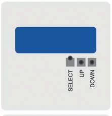
Contents

                            Contents                                        EN

                            1. General information                      4
                            2. Design and function                      5
                            3. Safety                                   6
                            4. Transport, packaging and storage        11
                            5. Commissioning, operation                12
                            6. Menu navigation                         21
                            7. Maintenance and cleaning                25
                            8. Dismounting, return and disposal        26
                            9. Specifications                          29
                            10. Accessories                            30
40414616.01 02/2018 EN/DE

                            WIKA operating instructions model A2G-52    3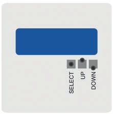
1. General information

     1. General information
     ■■ The differential pressure sensor described in the operating
         instructions has been manufactured using state-of-the-art technology.
EN       All components are subject to stringent quality and environmental
         criteria during production. Our management systems are certified to
         ISO 9001 and ISO 14001.

     ■■ These operating instructions contain important information on
         handling the instrument. Working safely requires that all safety
         instructions and work instructions are observed.

     ■■ Observe the relevant local accident prevention regulations and
         general safety regulations for the instrument's range of use.

     ■■ The operating instructions are part of the product and must be kept
         in the immediate vicinity of the instrument and readily accessible to
         skilled personnel at any time. Pass the operating instructions on to the
         next operator or owner of the instrument.

     ■■ Skilled personnel must have carefully read and understood the
         operating instructions prior to beginning any work.

     ■■ The general terms and conditions contained in the sales
         documentation shall apply.

     ■■ Subject to technical modifications.

     ■■ Further information:
         - Internet address:     www.wika.de / www.wika.com
                                 www.air2guide.com
         - Relevant data sheet: PE 88.03
                                                                                    40414616.01 02/2018 EN/DE

     4                                  WIKA operating instructions model A2G-52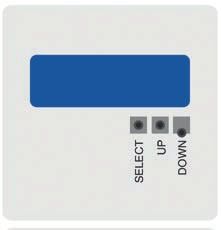
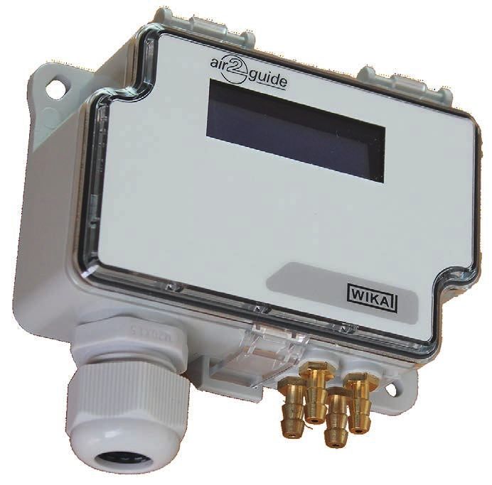
2. Design and function
2. Design and function
2.1 Overview
EN
Case
LC display
Process connection
Cable gland M16
2.2 Description
The model A2G-52 dual differential pressure sensor combines two
differential pressure sensors in one instrument, so that pressure can be
measured from two different control points.
The model A2G-52 has a Modbus and an input interface. By using
the input interface, up to two temperature sensors (Pt1000, Ni1000,
NTC10K) can be connected directly. Thus, temperature transmitters
which would otherwise be necessary can be saved. Alternatively,
40414616.01 02/2018 EN/DE
the input interface can also be assigned to an analogue input signal
(0 ... 10 V) or a potential-free contact.
WIKA operating instructions model A2G-52 5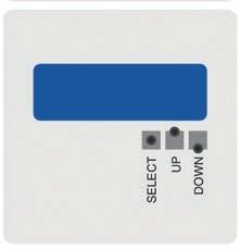
2. Design and function / 3. Safety

     2.3 Dimensions in mm

EN

     2.4 Scope of delivery
     ■■ Dual differential pressure sensor
     ■■ 2 mounting screws
     ■■ 4 duct connectors (option)
     ■■ 4 m PVC hose (option)
     Cross-check scope of delivery with delivery note.

     3. Safety
                                                                                    40414616.01 02/2018 EN/DE

     3.1 Explanation of symbols

               WARNING!
               ... indicates a potentially dangerous situation that can result in
               serious injury or death, if not avoided.

     6                                WIKA operating instructions model A2G-52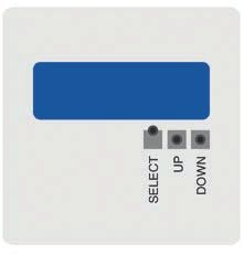
3. Safety

                                       CAUTION!
                                       ... indicates a potentially dangerous situation that can result in
                                       light injuries or damage to property or the environment, if not
                                       avoided.
                                                                                                             EN
                                       DANGER!
                                       ... identifies hazards caused by electrical power. Should the
                                       safety instructions not be observed, there is a risk of serious
                                       or fatal injury.

                                       WARNING!
                                       ... indicates a potentially dangerous situation that can result in
                                       burns, caused by hot surfaces or liquids, if not avoided.

                                       Information
                                       ... points out useful tips, recommendations and information for
                                       efficient and trouble-free operation.

                            3.2 Intended use
                            This dual differential pressure sensor is used for measuring differential
                            pressures of air and other non-inflammable and non-aggressive gases in
                            ventilation and air-conditioning applications.

                            This instrument is not permitted to be used in hazardous areas!

                            The instrument has been designed and built solely for the intended use
                            described here, and may only be used accordingly.

                            The technical specifications contained in these operating instructions
40414616.01 02/2018 EN/DE

                            must be observed. Improper handling or operation of the instrument
                            outside of its technical specifications requires the instrument to be taken
                            out of service immediately and inspected by an authorised WIKA service
                            engineer.

                            WIKA operating instructions model A2G-52                                     7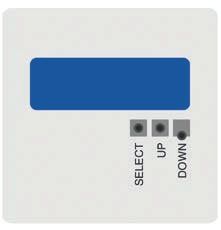
3. Safety

     The manufacturer shall not be liable for claims of any type based on
     operation contrary to the intended use.

     3.3 Improper use
EN
                WARNING!
                Injuries through improper use
                Improper use of the instrument can lead to hazardous
                situations and injuries.
                ▶▶ Refrain from unauthorised modifications to the instrument.
                ▶▶ Do not use the instrument within hazardous areas.
                ▶▶ Do not use the instrument with abrasive or viscous media.

     Any use beyond or different to the intended use is considered as
     improper use.

     Do not use this instrument in safety or emergency stop devices.

     3.4 Responsibility of the operator
     The instrument is used in the industrial sector. The operator is therefore
     responsible for legal obligations regarding safety at work.

     The safety instructions within these operating instructions, as well as the
     safety, accident prevention and environmental protection regulations for
     the application area must be maintained.

     The operator is obliged to maintain the product label in a legible
     condition.

     To ensure safe working on the instrument, the operating company must
     ensure
     ■■ that the operating personnel are regularly instructed in all topics
                                                                                   40414616.01 02/2018 EN/DE

        regarding work safety, first aid and environmental protection and know
        the operating instructions and in particular, the safety instructions
        contained therein.
     ■■ that the instrument is suitable for the particular application in
        accordance with its intended use.
     ■■ that personal protective equipment is available.

     8                                 WIKA operating instructions model A2G-52
3. Safety
3.5 Personnel qualification
WARNING!
Risk of injury should qualification be insufficient
Improper handling can result in considerable injury and EN
damage to equipment.
▶▶ The activities described in these operating instructions
may only be carried out by skilled personnel who have the
qualifications described below.
Skilled electrical personnel
Skilled electrical personnel are understood to be personnel who,
based on their technical training, know-how and experience as well
as their knowledge of country-specific regulations, current standards
and directives, are capable of carrying out work on electrical systems
and independently recognising and avoiding potential hazards. The
skilled electrical personnel have been specifically trained for the work
environment they are working in and know the relevant standards and
regulations. The skilled electrical personnel must comply with current
legal accident prevention regulations.
Operating personnel
The personnel trained by the operator are understood to be personnel
who, based on their education, knowledge and experience, are capable
of carrying out the work described and independently recognising
potential hazards.
Special operating conditions require further appropriate knowledge, e.g.
of aggressive media.
40414616.01 02/2018 EN/DE
WIKA operating instructions model A2G-52 93. Safety
3.6 Labelling, safety marks
Product label (example)
EN
Type: A2G-50
Range: -250 ... +250 Pa
Output: 0 ... 10 V / 4 ... 20 mA
Supply: DC 24 V / AC 24 V ±10 % < 1 W
Made in EU E-Nr. 66209848
Model
Measuring range
Power supply
Output
Serial number
Before mounting and commissioning the instrument, ensure
you read the operating instructions!
40414616.01 02/2018 EN/DE
10 WIKA operating instructions model A2G-524. Transport, packaging and storage
4. Transport, packaging and storage
4.1 Transport
Check the instrument for any damage that may have been caused by
transport. EN
Obvious damage must be reported immediately.
CAUTION!
Damage through improper transport
With improper transport, a high level of damage to property
can occur.
▶▶ When unloading packed goods upon delivery as well as
during internal transport, proceed carefully and observe
the symbols on the packaging.
▶▶ With internal transport, observe the instructions in chapter
4.2 “Packaging and storage”.
If the instrument is transported from a cold into a warm environment, the
formation of condensation may result in instrument malfunction. Before
putting it back into operation, wait for the instrument temperature and the
room temperature to equalise.
4.2 Packaging and storage
Do not remove packaging until just before mounting.
Keep the packaging as it will provide optimum protection during transport
(e.g. change in installation site, sending for repair).
Permissible conditions at the place of storage:
■■ Storage temperature: -20 ... +70 °C
Avoid exposure to the following factors:
40414616.01 02/2018 EN/DE
■■Direct sunlight or proximity to hot objects
■■Mechanical vibration, mechanical shock (putting it down hard)
■■Soot, vapour, humidity, dust and corrosive gases
■■Hazardous environments, flammable atmospheres
WIKA operating instructions model A2G-52 114. Transport ... / 5. Commissioning, operation
Store the instrument in its original packaging in a location that fulfils the
conditions listed above. If the original packaging is not available, pack
and store the instrument as described below:
1. Wrap the instrument in an antistatic plastic film.
EN 2. Place the instrument, along with the shock-absorbent material, in the
packaging.
3. If stored for a prolonged period of time (more than 30 days), place a
bag containing a desiccant inside the packaging.
5. Commissioning, operation
Personnel: Skilled electrical personnel
Tools: Voltage tester, screwdriver
Only use original parts (see chapter 10 “Accessories”).
WARNING!
Physical injuries and damage to property and the
environment caused by hazardous media
Upon contact with hazardous media (e.g. oxygen, acetylene,
flammable or toxic substances), harmful media (e.g. corrosive,
toxic, carcinogenic, radioactive), and also with refrigeration
plants and compressors, there is a danger of physical injuries
and damage to property and the environment.
Should a failure occur, aggressive media with extremely high
temperature and under high pressure or vacuum may be
present at the instrument.
▶▶ For these media, in addition to all standard regulations,
the appropriate existing codes or regulations must also be
followed.
40414616.01 02/2018 EN/DE
12 WIKA operating instructions model A2G-525. Commissioning, operation
CAUTION!
Damage to the instrument
When working on open electric circuits (printed circuit boards)
there is a risk of damaging sensitive electronic components
through electrostatic discharge. EN
▶▶ The correct use of grounded working surfaces and
personal armbands is required.
DANGER!
Danger to life caused by electric current
Upon contact with live parts, there is a direct danger to life.
▶▶ The instrument may only be installed and mounted by
skilled personnel.
▶▶ Operation using a defective power supply unit (e.g. short
circuit from the mains voltage to the output voltage) can
result in life-threatening voltages at the instrument!
1. Instrument fixing at the desired mounting location
(see chapter 5.1 “Instrument mounting”)
2. Opening the instrument cover, feeding the connection cable through
the cable gland and connecting the wires to the terminal block (see
chapter 5.3 “Electrical mounting”)
3. The instrument is now ready for configuration (see chapter 5.4
“Configuration”)
40414616.01 02/2018 EN/DE
WIKA operating instructions model A2G-52 135. Commissioning, operation
5.1 Instrument mounting
Screw the differential pressure transmitter onto a suitable vertical
surface and fix it horizontally with the mounting screws delivered with the
instrument.
EN
1. Select a mounting location (duct, wall, panel).
2. Remove the case cover and use the screw holes as a template.
3. Mount with suitable screws.
Instrument fixing
Instrument orientation
40414616.01 02/2018 EN/DE
14 WIKA operating instructions model A2G-525. Commissioning, operation
Application-related connections
Static pressure Filter monitoring Ventilator monitoring
measurement
EN
+ + - + -
- not
connected
+ + - - +
5.2 PCB diagram
Input sockets -
jumpers
LEDs
Display connections
Select Pressure sensors
Up A Input 1
B GND
Down 24V Input 2
GND GND
40414616.01 02/2018 EN/DE
Output Input
Menu buttons Rack-mounting terminals
WIKA operating instructions model A2G-52 155. Commissioning, operation
5.3 Electrical mounting
The instrument is designed to operate with safety extra-low voltage
(SELV). As a rule, operate the differential pressure transmitter in the
middle of the measuring range, since deviations can occur at the range
EN limits.
Operate the A2G-50 with a constant operating voltage (±0.2 V) and
ambient temperature. Prevent current/voltage spikes from switching the
power supply on or off.
For CE conformity, a properly grounded protective cable is required.
1. Unscrew the strain relief and feed the cable(s) through.
2. Connect the wires (see “Connection diagram”).
3. Tighten down the strain relief.
Connection diagram
■■ Output signal DC 0 ... 10 V
0 ... 10 V
not connected
V
24 V Power supply
AC/DC 24 V
GND
Pressure P Signal [U]
100 % 10.0 V
A
50 % 5.0 V
40414616.01 02/2018 EN/DE
0% 0.0 V
Time axis t [s]
Pressure P Signal [I]
100 % 20.0 mA
16 WIKA operating instructions model A2G-52Pressure P
V
Signal [U]
5. Commissioning, operation
100 % 10.0 V
■■ Output signal 4 ... 20 mA
50 %
not connected 5.0 V
4 ... 20 mA EN
24 V Power supply
A
AC/DC 24 V
0% GND 0.0 V
Time axis t [s]
Pressure P Signal [I]
100 % 20.0 mA
50 % 12.0 mA
0% 4.0 mA
Time axis t [s]
Connection diagram for input signals
(configuration see chapter 5.7 “Input signal configuration”)
J1
Pt1000 Input 1
J2
GND J3
Input 1 Input 2
NTC10k Input 2
GND
40414616.01 02/2018 EN/DE
Input 1: Pt1000 temperature sensor
Function 04: Read input value for register 3 x 0005
Input 2: NTC10K temperature sensor
Function 04: Read input value for register 3 x 0008
WIKA operating instructions model A2G-52 175. Commissioning, operation
5.4 Configuration
1. Remove the case cover.
2. Carry out a zero point setting (see chapter 5.5).
3. Connect measurement hoses.
EN (overpressure = connection “+”, vacuum = connection “-”)
4. Close the cover.
The instrument is now ready for operation.
5.5 Zero point setting
The zero point setting is done via
■■ Modbus®
■■ Manual push-button
Connect the voltage supply one hour before making the zero point
setting
1. Remove both hoses from the pressure connections ⊕ and ⊖.
2. Press the SELECT button briefly.
3. Wait until the red LED switches off again and install the hoses to the
pressure connections again.
In normal operation, carry out a zero point setting every 12 months.
40414616.01 02/2018 EN/DE
18 WIKA operating instructions model A2G-525. Commissioning, operation
5.6 Modbus register
FC04 - Read input register
Register Parameter Data type Value Display
description
EN
3x0001 Program version 16 bit 0 ... 1,000 0.00 ... 99.00
3x0002 Pressure 16 bit -250 ... 2,500 -250 ... 2,500 (Pa)
measurement A
3x0003 Pressure 16 bit -250 ... 2,500 -250 ... 2,500 (Pa)
measurement B
3x0004 Input 1: 0 ... 10 V 16 bit 0 ... 1,000 0 ... 100 %
3x0005 Input 1: Pt1000 16 bit 500 ... 500 -50 ... +50 °C
3x0006 Input 1: Ni1000 16 bit -500 ... 500 -50 ... +50 °C
3x0007 Input 1: Ni1000-LG 16 bit -500 ... 500 -50 ... +50 °C
3x0008 Input 1: NTC10k 16 bit -500 ... 500 -50 ... +50 °C
3x0009 Input 2: 0 ... 10 V 16 bit 0 ... 1,000 0 ... 100 %
3x0010 Input 2: Pt1000 16 bit -500 ... 500 -50 ... +50 °C
3x0011 Input 2: Ni1000 16 bit -500 ... 500 -50 ... +50 °C
3x0012 Input 2: Ni1000-L 16 bit -500 ... 500 -50 ... +50 °C
3x0013 Input 2: NTC10k 16 bit -500 ... 500 -50 ... +50 °C
FC02 - Read input status
Register Parameter Data type Value Display
description
1x0001 Input 1: BIN IN Bit 0 0 ... 1 On - Off
1x0002 Input 2: BIN IN Bit 0 0 ... 1 On - Off
FC05 - Write single coil
Register Parameter Data type Value Display
description
Zeroing Bit 0 0 ... 1 On - Off
40414616.01 02/2018 EN/DE
0x0001
FC06 - Write single register
Register Parameter Data type Value Display
description
4x0001 Beta value of NTC 16 bit 0 ... 30,000 0 ... 30,000
resistor (standard 4,220)
WIKA operating instructions model A2G-52 195. Commissioning, operation
5.7 Input signal configuration
The input signals can be read over Modbus® via RS-485 interface.
Set the jumpers on the PCB in accordance with the illustration. Read the
EN value from the correct register. Both inputs can be configured
independently.
J1
J2 NTC10k / BIN IN
J3
J1 J1
J2 J2 Pt1000 / Ni10007(-LG)
J3 J3
IN1 IN2
J1
J2 0 ... 10 V
J3
Signal Accuracy Resolution
0 ... 10 V < 0.5 % 0.1 %
NTC10K < 0.5 % 0.1 %
Pt1000 < 0.5 % 0.1 %
Ni1000/(-LG) < 0.5 % 0.1 %
40414616.01 02/2018 EN/DE
20 WIKA operating instructions model A2G-526. Menu navigation
6. Menu navigation
1. Select function mode
Move the “SELECT” button in any direction for at least MENU
EN
2 seconds to enter the menu.
▶▶ “MENU” is displayed.
2. Select Modbus® address: 1 … 247
Move the “DOWN” button once, shortly ADDRESS
▶▶ “ADDRESS” menu item is displayed
Move the “SELECT” button once, shortly, in order to ADDRESS
activate the “ADDRESS” selection. 99
▶▶ “ADDRESS” menu item flashes
Use “UP” or “DOWN” to find the desired Modbus®
address. ADDRESS
124
▶▶ Selection is displayed
Move the “SELECT” button once, shortly, in order to
40414616.01 02/2018 EN/DE
accept the selection. ADDRESS
124
WIKA operating instructions model A2G-52 216. Menu navigation
3. Select the baud rate: 9,600, 19,200, 38,400
Move the “DOWN” button once, shortly BAUD RATE
▶▶ “BAUD RATE” menu item is displayed 9600
EN
Move the “SELECT” button once, shortly, in order to BAUD RATE
activate the “BAUD RATE” selection. 9600
▶▶ “BAUD RATE” menu item flashes
Use “UP” or “DOWN” to find the desired baud rate. BAUD RATE
▶▶ Selection is displayed 19200
Move the “SELECT” button once, shortly, in order to
accept the selection. BAUD RATE
19200
40414616.01 02/2018 EN/DE
22 WIKA operating instructions model A2G-526. Menu navigation
4. Select the parity bit: None, even, odd
Move the “DOWN” button once, shortly PARITY BIT
▶▶ “PARITY BIT” menu item is displayed NONE
EN
Move the “SELECT” button once, shortly, in order to
PARITY BIT
activate the “PARITY BIT” selection. NONE
▶▶ “PARITY BIT” menu item flashes
Use “UP” or “DOWN” to find the desired parity bit.
▶▶ Selection is displayed PARITY BIT
EVEN
Move the “SELECT” button once, shortly, in order to
accept the selection. PARITY BIT
EVEN
40414616.01 02/2018 EN/DE
WIKA operating instructions model A2G-52 236. Menu navigation
5. Select pressure unit: Pa, inWC, mmWC, psi or mbar
Move the “DOWN” button once, shortly PRESS.UNIT
▶▶ “PRESS.UNIT” menu item is displayed Pa
EN
Move the “SELECT” button once, shortly, in order to PRESS.UNIT
Pa
activate the “PRESS.UNIT” selection.
▶▶ “PRESS.UNIT” menu item flashes
Use “UP” or “DOWN” to find the desired pressure unit. PRESS.UNIT
▶▶ Selection is displayed. inchWC
Move the “SELECT” button once, shortly, in order to
accept the selection. PRESS.UNIT
inchWC
6. Press the “SELECT” button in order to exit the
menu. SELECT
EXIT MENU
40414616.01 02/2018 EN/DE
24 WIKA operating instructions model A2G-527. Maintenance and cleaning
7. Maintenance and cleaning
Personnel: Skilled electrical personnel
Tools: Voltage tester, screwdriver
EN
For contact details see chapter 1 “General information” or the
back page of the operating instructions.
7.1 Maintenance
This instrument is maintenance-free and offers long service life provided
it is handled and operated properly.
Repairs must only be carried out by the manufacturer or appropriately
qualified skilled personnel.
Only use original parts (see chapter 10 “Accessories”).
7.2 Cleaning
CAUTION!
Physical injuries and damage to property and the
environment
Improper cleaning may lead to physical injuries and damage
to property and the environment. Residual media in the
dismounted instrument can result in a risk to persons, the
environment and equipment.
▶▶ Carry out the cleaning process as described below.
1. Before cleaning, correctly disconnect the instrument from the pressure
supply, switch it off and disconnect it from the mains.
40414616.01 02/2018 EN/DE
2. Use the requisite protective equipment.
3. Clean the instrument with a moist cloth (soapy water).
Electrical connections must not come into contact with moisture!
WIKA operating instructions model A2G-52 257. Maintenance and cleaning / 8. Dismounting ...
CAUTION!
Damage to the instrument
Improper cleaning may lead to damage to the instrument!
▶▶ Do not use any aggressive cleaning agents.
EN ▶▶ Do not use any hard or pointed objects for cleaning.
4. Wash or clean the dismounted instrument, in order to protect persons
and the environment from exposure to residual media.
8. Dismounting, return and disposal
Personnel: Skilled electrical personnel
Tools: Voltage tester, screwdriver
WARNING!
Physical injuries and damage to property and the
environment through residual media
Residual media in the dismounted instrument can result in a
risk to persons, the environment and equipment.
▶▶ Observe the information in the material safety data sheet
for the corresponding medium.
▶▶ Wash or clean the dismounted instrument, in order to
protect persons and the environment from exposure to
residual media.
40414616.01 02/2018 EN/DE
26 WIKA operating instructions model A2G-528. Dismounting, return and disposal
8.1 Dismounting
WARNING!
Physical injuries and damage to property and the
environment through residual media EN
Upon contact with hazardous media (e.g. oxygen, acetylene,
flammable or toxic substances), harmful media (e.g. corrosive,
toxic, carcinogenic, radioactive), and also with refrigeration
plants and compressors, there is a danger of physical injuries
and damage to property and the environment.
▶▶ Before storage of the dismounted instrument (following
use) wash or clean it, in order to protect persons and the
environment from exposure to residual media.
▶▶ Observe the information in the material safety data sheet
for the corresponding medium.
WARNING!
Risk of burns
During dismounting there is a risk of dangerously hot media
escaping.
▶▶ Let the instrument cool down sufficiently before
dismounting it!
DANGER!
Danger to life caused by electric current
Upon contact with live parts, there is a direct danger to life.
▶▶ The dismounting of the instrument may only be carried out
by skilled personnel.
▶▶ Remove the differential pressure sensor once the system
has been isolated from power sources.
WARNING!
40414616.01 02/2018 EN/DE
Physical injury
When dismounting, there is a danger from aggressive media
and high pressures.
▶▶ Observe the information in the material safety data sheet
for the corresponding medium.
▶▶ Dismount the differential pressure sensor when there is no
pressure.
WIKA operating instructions model A2G-52 278. Dismounting, return and disposal
8.2 Return
Strictly observe the following when shipping the instrument:
All instruments delivered to WIKA must be free from any kind of
EN hazardous substances (acids, bases, solutions, etc.) and must therefore
be cleaned before being returned.
WARNING!
Physical injuries and damage to property and the
environment through residual media
Residual media in the dismounted instrument can result in a
risk to persons, the environment and equipment.
▶▶ With hazardous substances, include the material safety
data sheet for the corresponding medium.
▶▶ Clean the instrument, see chapter 7.2 “Cleaning”.
When returning the instrument, use the original packaging or a suitable
transport packaging.
To avoid damage:
1. Wrap the instrument in an antistatic plastic film.
2. Place the instrument, along with the shock-absorbent material, in the
packaging.
Place shock-absorbent material evenly on all sides of the transport
packaging.
3. If possible, place a bag, containing a desiccant, inside the packaging.
4. Label the shipment as transport of a highly sensitive measuring
instrument.
Information on returns can be found under the heading
“Service” on our local website.
40414616.01 02/2018 EN/DE
8.3 Disposal
Incorrect disposal can put the environment at risk.
Dispose of instrument components and packaging materials in an
environmentally compatible way and in accordance with the country-
specific waste disposal regulations.
28 WIKA operating instructions model A2G-529. Specifications
9. Specifications
Dual differential pressure sensor, model A2G-52
Measuring element Piezo measuring cell
EN
Units of measure Pa, mbar, inWC, mmWC, psi
Measuring range -250 … +2,500 Pa and -250 … +7,500 Pa
Accuracy class -250 ... +2,500 Pa = pressure < 125 Pa = ±2 Pa + 1 %
Pressure > 125 Pa = ±1 Pa + 1 %
-250 ... +7,000 Pa = pressure < 125 Pa = ±2 Pa + 1.5 %
Pressure > 125 Pa = ±1 Pa + 1.5 %
all data refer to the current measured value (of the
measured pressure)
Process connection Connecting nozzle (copper alloy), lower mount, for
hoses with inner diameter 4 mm
Power supply UB AC 24 V or DC 24 V ±10 %
Electrical connection Cable gland M20
2 x 4 spring-clip terminals, max. 1.5 mm2
Output signal Modbus®
Display Two-line LC display (12 characters/line)
Line 1: Active measurement, input A
Line 2: Active measurement, input B
Case Plastic (ABS)
Cover: Polycarbonate (PC)
Permissible medium -10 … +50 °C
temperature
Relative humidity 0 … 95 % r. h., non-condensing
Ingress protection IP54
Weight 150 g
40414616.01 02/2018 EN/DE
WIKA operating instructions model A2G-52 299. Specifications / 10. Accessories
Modbus® version
Modbus® communication
Protocol Modbus® via serial interface
EN Transfer mode RTU
Interface RS-485
Byte format (11 bits) in RTU mode
Coding system: 8 bits binary
Bits per byte:
- 1 Start bit
- 8 data bits, lowest-order bit is sent first
- 1 bit for parity
- 1 stop bit
Baud rate 9,600, 19,200, 38,400 - adjustable in the configuration
Modbus® addresses 1 ... 247 addresses - adjustable in the configuration
For further specifications see WIKA data sheet PE 88.03 and the order
documentation.
10. Accessories
Description Order no.
Measuring hoses
PVC hose, inner diameter 4 mm, roll at 25 m 40217841
PVC hose, inner diameter 6 mm, roll at 25 m 40217850
Silicone hose, inner diameter 4 mm, roll at 25 m 40208940
Silicone hose, inner diameter 6 mm, roll at 25 m 40208958
40414616.01 02/2018 EN/DE
Duct connector for hose 4 and 6 mm 40217507
30 WIKA operating instructions model A2G-52Inhalt
Inhalt
DE
1. Allgemeines 32
2. Aufbau und Funktion 33
3. Sicherheit 34
4. Transport, Verpackung und Lagerung 39
5. Inbetriebnahme, Betrieb 40
6. Menüführung 49
7. Wartung und Reinigung 53
8. Demontage, Rücksendung und Entsorgung 54
9. Technische Daten 57
10. Zubehör 58
40414616.01 02/2018 EN/DE
WIKA Betriebsanleitung Typ A2G-52 311. Allgemeines
1. Allgemeines
■■ Der in der Betriebsanleitung beschriebene Differenzdrucksensor wird
nach dem aktuellen Stand der Technik gefertigt. Alle Komponenten
unterliegen während der Fertigung strengen Qualitäts- und Umwelt-
kriterien. Unsere Managementsysteme sind nach ISO 9001 und
DE ISO 14001 zertifiziert.
■■ Diese Betriebsanleitung gibt wichtige Hinweise zum Umgang mit dem
Gerät. Voraussetzung für sicheres Arbeiten ist die Einhaltung aller
angegebenen Sicherheitshinweise und Handlungsanweisungen.
■■ Die für den Einsatzbereich des Gerätes geltenden örtlichen Unfall-
verhütungsvorschriften und allgemeinen Sicherheitsbestimmungen
einhalten.
■■ Die Betriebsanleitung ist Produktbestandteil und muss in unmittel-
barer Nähe des Gerätes für das Fachpersonal jederzeit zugänglich
aufbewahrt werden. Betriebsanleitung an nachfolgende Benutzer
oder Besitzer des Gerätes weitergeben.
■■ Das Fachpersonal muss die Betriebsanleitung vor Beginn aller Arbei-
ten sorgfältig durchgelesen und verstanden haben.
■■ Es gelten die allgemeinen Geschäftsbedingungen in den Verkaufs-
unterlagen.
■■ Technische Änderungen vorbehalten.
■■ Weitere Informationen:
- Internet-Adresse: www.wika.de / www.wika.com
www.air2guide.com
- Zugehöriges Datenblatt: PE 88.03
40414616.01 02/2018 EN/DE
32 WIKA Betriebsanleitung Typ A2G-522. Aufbau und Funktion
2. Aufbau und Funktion
2.1 Überblick
DE
Gehäuse
LC-Display
Prozessanschluss
Kabelverschraubung M16
2.2 Beschreibung
Der doppelte Differenzdrucksensor Typ A2G-52 kombiniert zwei
Differenzdrucksensoren in einem Gerät, so dass der Druck von zwei
verschiedenen Kontrollpunkten gemessen werden kann.
Der A2G-52 hat eine Modbus®- und eine Input-Schnittstelle. Bei der
Verwendung der Input-Schnittstelle können bis zu zwei Temperatur-
sensoren (Pt1000, Ni1000, NTC10K) direkt angeschlossen werden.
Somit können ansonsten notwendige Temperaturtransmitter eingespart
40414616.01 02/2018 EN/DE
werden. Alternativ kann die Input-Schnittstelle auch mit einem analogen
Eingangssignal (0 ... 10 V) oder einem potentialfreien Kontakt belegt
werden.
WIKA Betriebsanleitung Typ A2G-52 332. Aufbau und Funktion / 3. Sicherheit
2.3 Abmessungen in mm
DE
2.4 Lieferumfang
■■ Doppelter Differenzdrucksensor
■■ 2 Befestigungsschrauben
■■ 4 Kanalanschlussnippel (Option)
■■ 4 m PVC-Schlauch (Option)
Lieferumfang mit dem Lieferschein abgleichen.
3. Sicherheit
40414616.01 02/2018 EN/DE
3.1 Symbolerklärung
WARNUNG!
... weist auf eine möglicherweise gefährliche Situation hin, die
zum Tod oder zu schweren Verletzungen führen kann, wenn
sie nicht gemieden wird.
34 WIKA Betriebsanleitung Typ A2G-523. Sicherheit
VORSICHT!
... weist auf eine möglicherweise gefährliche Situation hin, die
zu geringfügigen oder leichten Verletzungen bzw. Sach- und
Umweltschäden führen kann, wenn sie nicht gemieden wird.
GEFAHR!
DE
... kennzeichnet Gefährdungen durch elektrischen Strom. Bei
Nichtbeachtung der Sicherheitshinweise besteht die Gefahr
schwerer oder tödlicher Verletzungen.
WARNUNG!
... weist auf eine möglicherweise gefährliche Situation hin, die
durch heiße Oberflächen oder Flüssigkeiten zu Verbrennun-
gen führen kann, wenn sie nicht gemieden wird.
Information
... hebt nützliche Tipps und Empfehlungen sowie Informatio-
nen für einen effizienten und störungsfreien Betrieb hervor.
3.2 Bestimmungsgemäße Verwendung
Dieser doppelte Differenzdrucksensor dient zur Messung von Differenz-
drücken von Luft und anderen nicht brennbaren und nicht aggressiven
Gasen in der Luft- und Klimatechnik.
Dieses Gerät ist nicht für den Einsatz in explosionsgefährdeten Berei-
chen zugelassen!
Das Gerät ist ausschließlich für den hier beschriebenen bestimmungs-
gemäßen Verwendungszweck konzipiert und konstruiert und darf nur
40414616.01 02/2018 EN/DE
dementsprechend verwendet werden.
WIKA Betriebsanleitung Typ A2G-52 353. Sicherheit
Die technischen Spezifikationen in dieser Betriebsanleitung sind
einzuhalten. Eine unsachgemäße Handhabung oder ein Betreiben des
Gerätes außerhalb der technischen Spezifikationen macht die sofortige
Stilllegung und Überprüfung durch einen autorisierten WIKA-Service-
mitarbeiter erforderlich.
DE Ansprüche jeglicher Art aufgrund von nicht bestimmungsgemäßer
Verwendung sind ausgeschlossen.
3.3 Fehlgebrauch
WARNUNG!
Verletzungen durch Fehlgebrauch
Fehlgebrauch des Gerätes kann zu gefährlichen Situationen
und Verletzungen führen.
▶▶ Eigenmächtige Umbauten am Gerät unterlassen.
▶▶ Gerät nicht in explosionsgefährdeten Bereichen einsetzen.
▶▶ Gerät nicht für abrasive und viskose Messstoffe verwenden.
Jede über die bestimmungsgemäße Verwendung hinausgehende oder
andersartige Benutzung gilt als Fehlgebrauch.
Dieses Gerät nicht in Sicherheits- oder in Not-Aus-Einrichtungen benut-
zen.
3.4 Verantwortung des Betreibers
Das Gerät wird im gewerblichen Bereich eingesetzt. Der Betreiber unter-
liegt daher den gesetzlichen Pflichten zur Arbeitssicherheit.
Die Sicherheitshinweise dieser Betriebsanleitung, sowie die für den
Einsatzbereich des Gerätes gültigen Sicherheits-, Unfallverhütungs- und
Umweltschutzvorschriften einhalten.
40414616.01 02/2018 EN/DE
Der Betreiber ist verpflichtet das Typenschild lesbar zu halten.
36 WIKA Betriebsanleitung Typ A2G-523. Sicherheit
Für ein sicheres Arbeiten am Gerät muss der Betreiber sicherstellen,
■■ dass das Bedienpersonal regelmäßig in allen zutreffenden Fragen
von Arbeitssicherheit, Erste Hilfe und Umweltschutz unterwiesen wird,
sowie die Betriebsanleitung und insbesondere die darin enthaltenen
Sicherheitshinweise kennt.
■■ dass das Gerät gemäß der bestimmungsgemäßen Verwendung für
den Anwendungsfall geeignet ist. DE
■■ dass die persönliche Schutzausrüstung verfügbar ist.
3.5 Personalqualifikation
WARNUNG!
Verletzungsgefahr bei unzureichender Qualifikation
Unsachgemäßer Umgang kann zu erheblichen Personen-
und Sachschäden führen.
▶▶ Die in dieser Betriebsanleitung beschriebenen Tätigkei-
ten nur durch Fachpersonal nachfolgend beschriebener
Qualifikation durchführen lassen.
Elektrofachpersonal
Das Elektrofachpersonal ist aufgrund seiner fachlichen Ausbildung,
Kenntnisse und Erfahrungen sowie Kenntnis der landesspezifischen
Vorschriften, geltenden Normen und Richtlinien in der Lage, Arbeiten an
elektrischen Anlagen auszuführen und mögliche Gefahren selbstständig
zu erkennen und zu vermeiden. Das Elektrofachpersonal ist speziell
für das Arbeitsumfeld, in dem es tätig ist, ausgebildet und kennt die
relevanten Normen und Bestimmungen. Das Elektrofachpersonal muss
die Bestimmungen der geltenden gesetzlichen Vorschriften zur Unfall-
verhütung erfüllen.
Bedienpersonal
40414616.01 02/2018 EN/DE
Das vom Betreiber geschulte Personal ist aufgrund seiner Bildung,
Kenntnisse und Erfahrungen in der Lage, die beschriebenen Arbeiten
auszuführen und mögliche Gefahren selbstständig zu erkennen.
Spezielle Einsatzbedingungen verlangen weiteres entsprechendes
Wissen, z. B. über aggressive Medien.
WIKA Betriebsanleitung Typ A2G-52 373. Sicherheit
3.6 Beschilderung, Sicherheitskennzeichnungen
Typenschild (Beispiel)
DE
Type: A2G-50
Range: -250 ... +250 Pa
Output: 0 ... 10 V / 4 ... 20 mA
Supply: DC 24 V / AC 24 V ±10 % < 1 W
Made in EU E-Nr. 66209848
Typ
Messbereich
Hilfsenergie
Ausgang
Seriennummer
Vor Montage und Inbetriebnahme des Gerätes unbedingt die
Betriebsanleitung lesen!
40414616.01 02/2018 EN/DE
38 WIKA Betriebsanleitung Typ A2G-524. Transport, Verpackung und Lagerung
4. Transport, Verpackung und Lagerung
4.1 Transport
Gerät auf eventuell vorhandene Transportschäden untersuchen.
Offensichtliche Schäden unverzüglich mitteilen.
DE
VORSICHT!
Beschädigungen durch unsachgemäßen Transport
Bei unsachgemäßem Transport können Sachschäden in
erheblicher Höhe entstehen.
▶▶ Beim Abladen der Packstücke bei Anlieferung sowie
innerbetrieblichem Transport vorsichtig vorgehen und die
Symbole auf der Verpackung beachten.
▶▶ Bei innerbetrieblichem Transport die Hinweise unter
Kapitel 4.2 „Verpackung und Lagerung“ beachten.
Wird das Gerät von einer kalten in eine warme Umgebung transportiert,
so kann durch Kondensatbildung eine Störung der Gerätefunktion eintre-
ten. Vor einer erneuten Inbetriebnahme die Angleichung der Gerätetem-
peratur an die Raumtemperatur abwarten.
4.2 Verpackung und Lagerung
Verpackung erst unmittelbar vor der Montage entfernen.
Die Verpackung aufbewahren, denn diese bietet bei einem Transport
einen optimalen Schutz (z. B. wechselnder Einbauort, Reparatursen-
dung).
Zulässige Bedingungen am Lagerort:
■■ Lagertemperatur: -20 ... +70 °C
Folgende Einflüsse vermeiden:
40414616.01 02/2018 EN/DE
■■Direktes Sonnenlicht oder Nähe zu heißen Gegenständen
■■Mechanische Vibration, mechanischer Schock (hartes Aufstellen)
■■Ruß, Dampf, Feuchtigkeit, Staub und korrosive Gase
■■Explosionsgefährdete Umgebung, entzündliche Atmosphären
WIKA Betriebsanleitung Typ A2G-52 394. Transport ... / 5. Inbetriebnahme, Betrieb
Das Gerät in der Originalverpackung an einem Ort lagern, der die oben
gelisteten Bedingungen erfüllt. Wenn die Originalverpackung nicht
vorhanden ist, dann das Gerät wie folgt verpacken und lagern:
1. Das Gerät in eine antistatische Plastikfolie einhüllen.
2. Das Gerät mit dem Dämmmaterial in der Verpackung platzieren.
3. Bei längerer Einlagerung (mehr als 30 Tage) einen Beutel mit Trock-
DE nungsmittel der Verpackung beilegen.
5. Inbetriebnahme, Betrieb
Personal: Elektrofachpersonal
Werkzeuge: Spannungsprüfer, Schraubendreher
Nur Originalteile verwenden (siehe Kapitel 10 „Zubehör“).
WARNUNG!
Körperverletzungen, Sach- und Umweltschäden durch
gefährliche Messstoffe
Bei Kontakt mit gefährlichen Messstoffen (z. B. Sauerstoff,
Acetylen, brennbaren oder giftigen Stoffen), gesundheitsge-
fährdenden Messstoffen (z. B. ätzend, giftig, krebserregend,
radioaktiv) sowie bei Kälteanlagen, Kompressoren besteht die
Gefahr von Körperverletzungen, Sach- und Umweltschäden.
Am Gerät können im Fehlerfall aggressive Medien mit extremer
Temperatur und unter hohem Druck oder Vakuum anliegen.
▶▶ Bei diesen Messstoffen müssen über die gesamten
allgemeinen Regeln hinaus die einschlägigen Vorschriften
beachtet werden.
VORSICHT!
40414616.01 02/2018 EN/DE
Beschädigung des Gerätes
Bei Arbeiten mit offenen Schaltkreisen (Leiterplatten) besteht
die Gefahr empfindliche elektronische Bauteile durch elektro-
statische Entladung zu beschädigen.
▶▶ Die ordnungsgemäße Verwendung geerdeter Arbeitsflä-
chen und persönlicher Armbänder ist erforderlich.
40 WIKA Betriebsanleitung Typ A2G-525. Inbetriebnahme, Betrieb
GEFAHR!
Lebensgefahr durch elektrischen Strom
Bei Berührung mit spannungsführenden Teilen besteht unmit-
telbare Lebensgefahr.
▶▶ Einbau und Montage des Gerätes dürfen nur durch
Fachpersonal erfolgen.
▶▶ Bei Betrieb mit einem defekten Netzgerät (z. B. DE
Kurzschluss von Netzspannung zur Ausgangsspannung)
können am Gerät lebensgefährliche Spannungen auftre-
ten!
1. Gerätebefestigung an der gewünschten Montagestelle
(siehe Kapitel 5.1 „Gerätemontage“)
2. Öffnen des Gerätedeckels, Durchführung des Anschlusskabels
durch die Kabelverschraubung und Anschluss der Drähte an den
Klemmenblock (siehe Kapitel 5.3 „Elektrische Montage“)
3. Das Gerät ist nun bereit zur Konfiguration (siehe Kapitel 5.4
„Konfiguration“)
40414616.01 02/2018 EN/DE
WIKA Betriebsanleitung Typ A2G-52 415. Inbetriebnahme, Betrieb
5.1 Gerätemontage
Den Differenzdrucktransmitter auf einer geeigneten vertikalen Fläche
aufschrauben und waagerecht mit den beiliegenden Befestigungs-
schrauben befestigen.
1. Montageort wählen (Kanal, Wand, Panel).
DE 2. Gehäusedeckel entfernen und die Schraubenlöcher als Schablone
verwenden.
3. Mit geeigneten Schrauben montieren.
Gerätebefestigung
Geräteausrichtung
40414616.01 02/2018 EN/DE
42 WIKA Betriebsanleitung Typ A2G-525. Inbetriebnahme, Betrieb
Anwendungsbezogene Anschlüsse
Statische Filter- Ventilator-
Druckmessung überwachung überwachung
DE
+ + - + -
- nicht
angeschlossen
+ + - - +
5.2 Platinenschema
Eingangsbuchsen �
Jumper
LEDs
Displayanschlüsse
Select Drucksensoren
Up A Eingang 1
B GND
Down 24V Eingang 2
GND GND
40414616.01 02/2018 EN/DE
Ausgang Eingang
Menütasten Reihenklemmen
WIKA Betriebsanleitung Typ A2G-52 435. Inbetriebnahme, Betrieb
5.3 Elektrische Montage
Das Gerät ist für den Betrieb an Schutzkleinspannung (SELV) ausgelegt.
Den Differenzdrucktransmitter in der Regel in der Messbereichsmitte
betreiben, da an den Messbereichsendpunkten erhöhte Abweichungen
auftreten können.
A2G-50 bei einer konstanten Betriebsspannung (±0,2 V) und
DE Umgebungstemperatur betreiben. Strom-/Spannungsspitzen beim Ein-/
Ausschalten der Hilfsenergie bauseitig vermeiden.
Für die CE-Konformität ist ein ordnungsgemäß geerdetes Schutzkabel
erforderlich.
1. Die Zugentlastung abschrauben und das (die) Kabel durchführen.
2. Die Drähte anschließen (siehe „Anschlussschema“).
3. Zugentlastung festziehen.
Anschlussschema
■■ Ausgangssignal DC 0 ... 10 V
0 ... 10 V
nicht angeschlossen
V
24 V Hilfsenergie
GND Ausgangssignal
AC/DC 24 V
A2G-25 Volumenstrommessumformer
Signalkurve [U] Signal-Ausgang [U] Spannung 0…10 V DC
Druck P Signal [U]
100 % 10.0 V
A
40414616.01 02/2018 EN/DE
50 % 5.0 V
0% 0.0 V
Zeitachse t [s]
Signalkurve [I] Signal-Ausgang [I] Strom 4…20 mA
Druck P Signal [I]
44 100 % WIKA Betriebsanleitung
20.0 mA Typ A2G-52Signalkurve [U] Signal-Ausgang [U] Spannung 0…10 V DC
Druck P
V
Signal [U]
5. Inbetriebnahme, Betrieb
100 % 10.0 V
■■ Ausgangssignal 4 ... 20 mA
50 %
nicht angeschlossen 5.0 V
4 ... 20 mA
24 V Hilfsenergie
A
0% GND AC/DC 24 V
0.0 V
DE
Zeitachse t [s]
Signalkurve [I] Signal-Ausgang [I] Strom 4…20 mA
Druck P Signal [I]
100 % 20.0 mA
50 % 12.0 mA
0% 4.0 mA
Zeitachse t [s]
Erstellt: Philipp Kottmann am: 29.04.2015 Datei: Signal_A2G-25.docx Seite 2 von 1
MANOMETER AG T +41(0)41 919 72 72
Industriestrasse 11 F +41(0)41 919 72 73
CH-6285 Hitzkirch E-Mail info@manometer.ch
Anschlussschema für Eingangssignale
(Konfiguration sieeh Kapitel 5.7 „Konfiguration der Eingangssignale“)
J1
Pt1000 Eingang 1
J2
GND J3
Eingang 1 Eingang 2
NTC10k Eingang 2
GND
40414616.01 02/2018 EN/DE
Eingang 1: Pt1000-Temperatursensor
Funktion 04: Lese Eingangswert für Register 3 x 0005
Eingang 2: NTC10K-Temperatursensor
Funktion 04: Lese Eingangswert für Register 3 x 0008
WIKA Betriebsanleitung Typ A2G-52 455. Inbetriebnahme, Betrieb
5.4 Konfiguration
1. Gehäusedeckel entfernen.
2. Nullpunkteinstellung durchführen (siehe Kapitel 5.5).
3. Druckmessschläuche anschließen.
(Überdruck = Anschluss „+“, Unterdruck = Anschluss „-“)
4. Deckel schließen.
DE
Das Gerät ist nun betriebsbereit.
5.5 Nullpunkteinstellung
Die Nullpunkteinstellung erfolgt über
■■ Modbus®
■■ Manueller Druckknopf
Die Spannungsversorgung eine Stunde vor der Nullpunkteinstel-
lung anschließen!
1. Beide Schläuche von den Druckanschlüssen ⊕ und ⊖ lösen.
2. SELECT-Taste kurz drücken.
3. Warten bis sich die rote LED wieder ausschaltet und anschließend die
Schläuche wieder an die Druckanschlüsse installieren.
Bei normalem Betrieb die Nullpunkteinstellung alle 12 Monate vorneh-
men.
40414616.01 02/2018 EN/DE
46 WIKA Betriebsanleitung Typ A2G-525. Inbetriebnahme, Betrieb
5.6 Modbus-Verzeichnis
FC04 - Eingangswörter lesen
Register Parameter- Datentyp Wert Anzeige
beschreibung
3x0001 Programmversion 16 Bit 0 ... 1.000 0,00 ... 99,00
3x0002 Druckmessung A 16 Bit -250 ... 2.500 -250 ... 2.500 (Pa) DE
3x0003 Druckmessung B 16 Bit -250 ... 2.500 -250 ... 2.500 (Pa)
3x0004 Eingang 1: 0 ... 10 V 16 Bit 0 ... 1.000 0 ... 100 %
3x0005 Eingang 1: Pt1000 16 Bit 500 ... 500 -50 ... +50 °C
3x0006 Eingang 1: Ni1000 16 Bit -500 ... 500 -50 ... +50 °C
3x0007 Eingang 1: Ni1000-LG 16 Bit -500 ... 500 -50 ... +50 °C
3x0008 Eingang 1: NTC10k 16 Bit -500 ... 500 -50 ... +50 °C
3x0009 Eingang 2: 0 ... 10 V 16 Bit 0 ... 1.000 0 ... 100 %
3x0010 Eingang 2: Pt1000 16 Bit -500 ... 500 -50 ... +50 °C
3x0011 Eingang 2: Ni1000 16 Bit -500 ... 500 -50 ... +50 °C
3x0012 Eingang 2: Ni1000-L 16 Bit -500 ... 500 -50 ... +50 °C
3x0013 Eingang 2: NTC10k 16 Bit -500 ... 500 -50 ... +50 °C
FC02 - Eingangsbit lesen
Register Parameter- Datentyp Wert Anzeige
beschreibung
1x0001 Eingang 1: BIN IN Bit 0 0 ... 1 Ein - Aus
1x0002 Eingang 2: BIN IN Bit 0 0 ... 1 Ein - Aus
FC05 - Ausgangsbit schreiben
Register Parameter- Datentyp Wert Anzeige
beschreibung
0x0001 Nullabgleich Bit 0 0 ... 1 Ein - Aus
40414616.01 02/2018 EN/DE
FC06 - Halteregister schreiben
Register Parameter- Datentyp Wert Anzeige
beschreibung
4x0001 Betawert von NTC- 16 Bit 0 ... 30.000 0 ... 30.000
Widerstand (Standard 4.220)
WIKA Betriebsanleitung Typ A2G-52 475. Inbetriebnahme, Betrieb
5.7 Konfiguration der Eingangssignale
Die Eingangssignale können über Modbus® via RS-485-Schnittstelle
gelesen werden.
Die Jumper auf der Platine gemäß Abbildung einstellen. Den Wert vom
korrekten Register ablesen. Beide Eingänge können unabhängig
DE voneinander konfiguriert werden.
J1
J2 NTC10k / BIN IN
J3
J1 J1
J2 J2 Pt1000 / Ni10007(-LG)
J3 J3
IN1 IN2
J1
J2 0 ... 10 V
J3
Signal Genauigkeit Auflösung
0 ... 10 V < 0,5 % 0,1 %
NTC10K < 0,5 % 0,1 %
Pt1000 < 0,5 % 0,1 %
Ni1000/(-LG) < 0,5 % 0,1 %
40414616.01 02/2018 EN/DE
48 WIKA Betriebsanleitung Typ A2G-526. Menüführung
6. Menüführung
1. Funktionsmodus wählen
Die Taste „SELECT“ für mindestens 2 Sekunden in MENU
eine beliebige Richtung bewegen, um in das Menu zu
gelangen.
▶▶ „MENU“ erscheint DE
2. Modbus®-Adresse wählen: 1 … 247
Taste „DOWN“ einmal kurz bewegen ADDRESS
▶▶ Menüpunkt „ADDRESS“ erscheint
Taste „SELECT“ einmal kurz bewegen, um die ADDRESS
Auswahl „ADDRESS“ zu aktivieren. 99
▶▶ Menüpunkt „ADDRESS“ blinkt
„UP“ oder „DOWN“ verwenden, um die gewünschte
Modbus®-Adresse zu finden. ADDRESS
▶▶ Auswahl wird angezeigt
124
40414616.01 02/2018 EN/DE
Taste „SELECT“ einmal kurz bewegen, um die
Auswahl zu bestätigen. ADDRESS
124
WIKA Betriebsanleitung Typ A2G-52 496. Menüführung
3. Baudrate wählen: 9.600, 19.200, 38.400
Taste „DOWN“ einmal kurz bewegen BAUD RATE
▶▶ Menüpunkt „BAUD RATE“ erscheint 9600
DE
Taste „SELECT“ einmal kurz bewegen, um die
Auswahl „BAUD RATE“ zu aktivieren. BAUD RATE
9600
▶▶ Menüpunkt „BAUD RATE“ blinkt
„UP“ oder „DOWN“ verwenden, um die gewünschte
Baudrate zu finden. BAUD RATE
▶▶ Auswahl wird angezeigt
19200
Taste „SELECT“ einmal kurz bewegen, um die
Auswahl zu bestätigen. BAUD RATE
19200
40414616.01 02/2018 EN/DE
50 WIKA Betriebsanleitung Typ A2G-526. Menüführung
4. Paritäts-Bit wählen: None, Even, Odd
Taste „DOWN“ einmal kurz bewegen PARITY BIT
▶▶ Menüpunkt „PARITY BIT“ erscheint NONE
DE
Taste „SELECT“ einmal kurz bewegen, um die
Auswahl „PARITY BIT“ zu aktivieren. PARITY BIT
NONE
▶▶ Menüpunkt „PARITY BIT“ blinkt
„UP“ oder „DOWN“ verwenden, um den gewünschten
Päritäts-Bit zu finden. PARITY BIT
EVEN
▶▶ Auswahl wird angezeigt
Taste „SELECT“ einmal kurz bewegen, um die
Auswahl zu bestätigen. PARITY BIT
EVEN
40414616.01 02/2018 EN/DE
WIKA Betriebsanleitung Typ A2G-52 516. Menüführung
5. Druckeinheit wählen: Pa, inWC, mmWC, psi oder mbar
Taste „DOWN“ einmal kurz bewegen PRESS.UNIT
▶▶ Menüpunkt „PRESS.UNIT“ erscheint Pa
DE
Taste „SELECT“ einmal kurz bewegen, um die PRESS.UNIT
Pa
Auswahl „PRESS.UNIT“ zu aktivieren.
▶▶ Menüpunkt „PRESS.UNIT“ blinkt
„UP“ oder „DOWN“ verwenden, um die gewünschte PRESS.UNIT
Druckeinheit zu finden. inchWC
▶▶ Auswahl wird angezeigt.
Taste „SELECT“ einmal kurz bewegen, um die
Auswahl zu bestätigen. PRESS.UNIT
inchWC
6. Taste „SELECT“ drücken, um das Menü zu
verlassen. SELECT
EXIT MENU
40414616.01 02/2018 EN/DE
52 WIKA Betriebsanleitung Typ A2G-527. Wartung und Reinigung
7. Wartung und Reinigung
Personal: Elektrofachpersonal
Werkzeuge: Spannungsprüfer, Schraubendreher
Kontaktdaten siehe Kapitel 1 „Allgemeines“ oder Rückseite DE
der Betriebsanleitung.
7.1 Wartung
Dieses Gerät ist wartungsfrei und zeichnet sich bei sachgemäßer
Behandlung und Bedienung durch eine hohe Lebensdauer aus.
Reparaturen sind ausschließlich vom Hersteller oder entsprechend
qualifiziertem Fachpersonal durchzuführen.
Nur Originalteile verwenden (siehe Kapitel 10 „Zubehör“).
7.2 Reinigung
VORSICHT!
Körperverletzungen, Sach- und Umweltschäden
Eine unsachgemäße Reinigung führt zu Körperverletzungen,
Sach- und Umweltschäden. Messstoffreste im ausgebauten
Gerät können zur Gefährdung von Personen, Umwelt und
Einrichtung führen.
▶▶ Reinigungsvorgang wie folgt beschrieben durchführen.
1. Vor der Reinigung das Gerät ordnungsgemäß von der Druckversor-
gung trennen, ausschalten und vom Netz trennen.
2. Notwendige Schutzausrüstung verwenden.
40414616.01 02/2018 EN/DE
3. Das Gerät mit einem (in Seifenlauge) angefeuchteten Tuch reinigen.
Elektrische Anschlüsse nicht mit Feuchtigkeit in Berührung bringen!
WIKA Betriebsanleitung Typ A2G-52 537. Wartung und Reinigung / 8. Demontage ...
VORSICHT!
Beschädigung des Gerätes
Eine unsachgemäße Reinigung führt zur Beschädigung des
Gerätes!
▶▶ Keine aggressiven Reinigungsmittel verwenden.
▶▶ Keine harten und spitzen Gegenstände zur Reinigung
DE verwenden.
4. Ausgebautes Gerät spülen bzw. säubern, um Personen und Umwelt
vor Gefährdung durch anhaftende Messstoffreste zu schützen.
8. Demontage, Rücksendung und Entsorgung
Personal: Elektrofachpersonal
Werkzeuge: Spannungsprüfer, Schraubendreher
WARNUNG!
Körperverletzungen, Sach- und Umweltschäden durch
Messstoffreste
Messstoffreste im ausgebauten Gerät können zur Gefähr-
dung von Personen, Umwelt und Einrichtung führen.
▶▶ Angaben im Sicherheitsdatenblatt für den entsprechenden
Messstoff beachten.
▶▶ Ausgebautes Gerät spülen bzw. säubern, um Personen
und Umwelt vor Gefährdung durch anhaftende Messstoff-
reste zu schützen.
40414616.01 02/2018 EN/DE
54 WIKA Betriebsanleitung Typ A2G-528. Demontage, Rücksendung und Entsorgung
8.1 Demontage
WARNUNG!
Körperverletzungen, Sach- und Umweltschäden durch
Messstoffreste
Bei Kontakt mit gefährlichen Messstoffen (z. B. Sauerstoff,
Acetylen, brennbaren oder giftigen Stoffen), gesundheitsge- DE
fährdenden Messstoffen (z. B. ätzend, giftig, krebserregend,
radioaktiv) sowie bei Kälteanlagen, Kompressoren besteht die
Gefahr von Körperverletzungen, Sach- und Umweltschäden.
▶▶ Vor der Einlagerung das ausgebaute Gerät (nach Betrieb)
spülen bzw. säubern, um Personen und Umwelt vor Gefähr-
dung durch anhaftende Messstoffreste zu schützen.
▶▶ Angaben im Sicherheitsdatenblatt für den entsprechenden
Messstoff beachten.
WARNUNG!
Verbrennungsgefahr
Beim Ausbau besteht Gefahr durch austretende, gefährlich
heiße Messstoffe.
▶▶ Vor dem Ausbau das Gerät ausreichend abkühlen lassen!
GEFAHR!
Lebensgefahr durch elektrischen Strom
Bei Berührung mit spannungsführenden Teilen besteht unmit-
telbare Lebensgefahr.
▶▶ Die Demontage des Gerätes darf nur durch Fachpersonal
erfolgen.
▶▶ Differenzdrucksensor im stromlosen Zustand demontieren.
WARNUNG!
Körperverletzung
40414616.01 02/2018 EN/DE
Bei der Demontage besteht Gefahr durch aggressive Medien
und hohe Drücke.
▶▶ Angaben im Sicherheitsdatenblatt für den entsprechenden
Messstoff beachten.
▶▶ Differenzdrucksensor im drucklosen Zustand demontieren.
WIKA Betriebsanleitung Typ A2G-52 558. Demontage, Rücksendung und Entsorgung
8.2 Rücksendung
Beim Versand des Gerätes unbedingt beachten:
Alle an WIKA gelieferten Geräte müssen frei von Gefahrstoffen (Säuren,
Laugen, Lösungen, etc.) sein und sind daher vor der Rücksendung zu
reinigen.
DE
WARNUNG!
Körperverletzungen, Sach- und Umweltschäden durch
Messstoffreste
Messstoffreste im ausgebauten Gerät können zur Gefähr-
dung von Personen, Umwelt und Einrichtung führen.
▶▶ Bei Gefahrenstoffen das Sicherheitsdatenblatt für den
entsprechenden Messstoff beilegen.
▶▶ Gerät reinigen, siehe Kapitel 7.2 „Reinigung“.
Zur Rücksendung des Gerätes die Originalverpackung oder eine geeig-
nete Transportverpackung verwenden.
Um Schäden zu vermeiden:
1. Das Gerät in eine antistatische Plastikfolie einhüllen.
2. Das Gerät mit dem Dämmmaterial in der Verpackung platzieren.
Zu allen Seiten der Transportverpackung gleichmäßig dämmen.
3. Wenn möglich einen Beutel mit Trocknungsmittel der Verpackung
beifügen.
4. Sendung als Transport eines hochempfindlichen Messgerätes
kennzeichnen.
Hinweise zur Rücksendung befinden sich in der Rubrik
„Service“ auf unserer lokalen Internetseite.
40414616.01 02/2018 EN/DE
8.3 Entsorgung
Durch falsche Entsorgung können Gefahren für die Umwelt entstehen.
Gerätekomponenten und Verpackungsmaterialien entsprechend den
landesspezifischen Abfallbehandlungs- und Entsorgungsvorschriften
umweltgerecht entsorgen.
56 WIKA Betriebsanleitung Typ A2G-52You can also read