Single point load cell, models F4801, F4802, F4818 Plattformwägezelle, Typen F4801, F4802, F4818 - Single point load cell, models F4801, F4802 F4818
←
→
Page content transcription
If your browser does not render page correctly, please read the page content below
Operating instructions
                                  Betriebsanleitung

Single point load cell, models F4801, F4802, F4818         EN

Plattformwägezelle, Typen F4801, F4802, F4818              DE

      Single point load cell, models F4801, F4802 F4818
EN Operating instructions, models F4801, F4802, F4818 Page                   3 - 26

DE Betriebsanleitung, Typen F4801, F4802, F4818                Seite        27 - 49

                                                                                       ADPR1X914110.01 07/2021 EN/DE

    2                        WIKA operating instructions, models F4801, F4802, F4818
Contents

                                Contents
                                1. General information                                                                                         4
                                2. Design and function                                                                                         5
                                    2.1 Overview  .   .   .   .   .   .   .   .   .   .   .   .   .   .   .   .   .   .   .   .   .   .   . 5
                                    2.2 Description . . . . . . . . . . . . . . . . . . . . . . . 5                                                EN
                                    2.3 Scope of delivery  .  .  .  .  .  .  .  .  .  .  .  .  .  .  .  .  .  .  .  . 5
                                3. Safety                                                                                                      6
                                    3.1 Explanation of symbols  .  .  .  .  .  .  .  .  .  .  .  .  .  .  .  .  .  . 6
                                    3.2 Intended use  .  .  .  .  .  .  .  .  .  .  .  .  .  .  .  .  .  .  .  .  .  . 6
                                    3.3 Improper use  .   .   .   .   .   .   .   .   .   .   .   .   .   .   .   .   .   .   .   .   .   . 7
                                    3.4 Responsibility of the operator   .   .   .   .   .   .   .   .   .   .   .   .   .   .   .   . 7
                                    3.5 Personnel qualification  .   .   .   .   .   .   .   .   .   .   .   .   .   .   .   .   .   .   . 8
                                    3.6 Personal protective equipment  .   .   .   .   .   .   .   .   .   .   .   .   .   .   .   . 8
                                    3.7 Labelling, safety marks  .  .  .  .  .  .  .  .  .  .  .  .  .  .  .  .  .  . 9
                                4. Transport, packaging and storage                                                                           10
                                    4.1 Transport  .   .   .   .   .   .   .   .   .   .   .   .   .   .   .   .   .   .   .   .   .   .   . 10
                                    4.2 Packaging and storage  .  .  .  .  .  .  .  .  .  .  .  .  .  .  .  .  .  . 10
                                5. Commissioning, operation                                                                                   11
                                    5.1 Mounting preparation  .  .  .  .  .  .  .  .  .  .  .  .  .  .  .  .  .  .  . 11
                                    5.2 Mounting instructions  .  .  .  .  .  .  .  .  .  .  .  .  .  .  .  .  .  .  . 11
                                    5.3 Mounting the single point load cell  .   .   .   .   .   .   .   .   .   .   .   .   .   .  12
                                    5.4 Electrical connection   .   .   .   .   .   .   .   .   .   .   .   .   .   .   .   .   .   .   . 13
                                6. Faults                                                                                                     14
                                7. Maintenance and cleaning                                                                                   14
                                    7.1 Maintenance  .  .  .  .  .  .  .  .  .  .  .  .  .  .  .  .  .  .  .  .  .  . 14
                                    7.2 Cleaning  .  .  .  .  .  .  .  .  .  .  .  .  .  .  .  .  .  .  .  .  .  .  . 14
                                8. Dismounting, return and disposal                                                                           15
                                    8.1 Dismounting  .  .  .  .  .  .  .  .  .  .  .  .  .  .  .  .  .  .  .  .  .  . 15
                                    8.2 Return  .   .   .   .   .   .   .   .   .   .   .   .   .   .   .   .   .   .   .   .   .   .   .   . 15
                                    8.3 Disposal  .  .  .  .  .  .  .  .  .  .  .  .  .  .  .  .  .  .  .  .  .  .  . 15
                                9. Specifications                                                                                             16
                                    9.1 Approvals  .  .  .  .  .  .  .  .  .  .  .  .  .  .  .  .  .  .  .  .  .  .  . 21
                                10. Accessories                                                                                               22
                                    10.1 Cable  .  .  .  .  .  .  .  .  .  .  .  .  .  .  .  .  .  .  .  .  .  .  .  . 22
ADPR1X914110.01 07/2021 EN/DE

                                    10.2 B1940 Cable amplifier   .   .   .   .   .   .   .   .   .   .   .   .   .   .   .   .   .   . 22
                                    10.3 E1932 strain gauge weighing electronics  .   .   .   .   .   .   .   .   .   .   .  23
                                    10.4 B6578 junction box   .   .   .   .   .   .   .   .   .   .   .   .   .   .   .   .   .   .   . 23
                                    10.5 Large display for mA or V signals E1931X800   .   .   .   .   .   .   .   .   .   . 24
                                Annex: EU declaration of conformity                                                                           25

                                 WIKA operating instructions, models F4801, F4802, F4818                                                      3
1. General information

     1. General information
     ■ The single point load cells described in the operating instructions have been
          designed and manufactured using state-of-the-art technology. All components
EN        are subject to stringent quality and environmental criteria during production. Our
          management systems are certified to ISO 9001.
     ■    These operating instructions contain important information on handling the
          instrument. Working safely requires that all safety instructions and work instructions
          are observed.
     ■    Observe the relevant local accident prevention regulations and general safety
          regulations for the instrument’s range of use.
     ■    The operating instructions are part of the product and must be kept in the immediate
          vicinity of the instrument and readily accessible to skilled personnel at any time. Pass
          the operating instructions on to the next operator or owner of the instrument.
     ■    Skilled personnel must have carefully read and understood the operating instructions
          prior to beginning any work.
     ■    The general terms and conditions contained in the sales documentation shall apply.
     ■    Subject to technical modifications.

     Further information:
          - Internet address:             www.wika.com
          - Relevant data sheet:          FO 53.10 (model F4801)
                                          FO 53.13 (model F4802)
                                          FO 53.14 (model F4818)
          - Application consultant:       Tel.: +49 9372 132-0
                                          Fax: +49 9372 132-406
                                          info@wika.com

     Abbreviations, definitions
     4-wire     Two connection lines for the voltage supply
                One connection lead for the measuring signal
     UB+        Positive power supply terminal
     UB-        Negative power supply terminal
     S+         Positive output terminal
     S-         Negative output terminal
     Shield     Case
                                                                                                     ADPR1X914110.01 07/2021 EN/DE

     SG         Strain gauge

      4                                   WIKA operating instructions, models F4801, F4802, F4818
2. Design and function
2. Design and function
2.1 Overview
Force introduction EN
Measuring spring
Electrical connection
F
F
2.2 Description
The single point load cell is intended for the measurement of static compression forces
in weighing applications. The single point load cell consists of a measuring spring on
which strain gauges (SGs) are applied. The measuring body is made of aluminium
and is elastically deformed by a force introduced in the force direction. The resulting
mechanical tensions are measured by the strain gauges and output as an electrical
output signal.
The strain gauges are arranged so that two of them are tensioned and the other two are
compressed when a force is applied to the single point load cell.
The single point load cell circuit includes correction and compensation resistors to elimi-
ADPR1X914110.01 07/2021 EN/DE
nate unwanted effects on the zero signal and characteristic value.
2.3 Scope of delivery
■ Single point load cell
■ Operating instructions
WIKA operating instructions, models F4801, F4802, F4818 5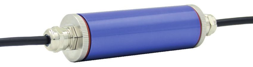
3. Safety

     3. Safety
     3.1 Explanation of symbols

EN
                  WARNING!
                  ... indicates a potentially dangerous situation that can result in serious
                  injury or death, if not avoided.

                   CAUTION!
                   ... indicates a potentially dangerous situation that can result in light injuries
                   or damage to property or the environment, if not avoided.

                   Information
                   ... points out useful tips, recommendations and information for efficient
                   and trouble-free operation.

     2.4 Intended use

     The single point load cells are designed for measuring static forces.

      Model                        Version/Measuring ranges
      F4801                        0 … 3 kg to 0 ... 250 kg
      F4802                        0 … 0.3 kg to 0 ... 10 kg
      F4818                        0 … 20 kg to 0 ... 500 kg

     These instruments have been designed and tested in accordance with the relevant
                                                                                                       ADPR1X914110.01 07/2021 EN/DE

     safety regulations for electronic measuring instruments. Any usage outside of this is
     deemed to be improper. The perfect functioning and operational safety of the single
     point load cell can only be guaranteed when complying with the instructions given in the
     operating instructions. During its use, the legal and safety regulations (e.g. VDE 0100)
     required for the particular application must additionally be observed. This also applies
     accordingly when using accessories. Faultless and safe operation of this single point
     load cell requires proper transport, professional storage, installation and mounting and
     careful operation and corrective maintenance.

      6                                  WIKA operating instructions, models F4801, F4802, F4818
3. Safety

                                The instrument has been designed and built solely for the intended use described here,
                                and may only be used accordingly. The technical specifications contained in these
                                operating instructions must be observed. Improper handling or operation of the instru-
                                ment outside of its technical specifications requires the instrument to be taken out of
                                service immediately and inspected by an authorised service engineer.                           EN
                                Handle electronic precision measuring instruments with the required care (protect from
                                humidity, impacts, strong magnetic fields, static electricity and extreme temperatures,
                                do not insert any objects into the instrument or its openings). Plugs and sockets must be
                                protected from contamination.

                                The manufacturer shall not be liable for claims of any type based on operation contrary
                                to the intended use.

                                2.5 Improper use

                                              WARNING!
                                              Injuries through improper use
                                              Improper use of the instrument can lead to hazardous situations and
                                              injuries.
                                              ▶ Refrain from unauthorised modifications to the instrument.

                                Any use beyond or different to the intended use is considered as improper use.

                                2.6 Responsibility of the operator
                                The instrument is used in the industrial sector. The operator is therefore responsible for
                                legal obligations regarding safety at work.

                                The safety instructions within these operating instructions, as well as the safety, accident
                                prevention and environmental protection regulations for the application area must be
                                maintained.

                                The operator is obliged to maintain the product label in a legible condition.

                                To ensure safe working on the instrument, the operating company must ensure
                                ■ that suitable first-aid equipment is available and aid is provided whenever required.
ADPR1X914110.01 07/2021 EN/DE

                                ■ that the skilled electrical personnel are regularly instructed in all topics regarding
                                  work safety, first aid and environmental protection and know the operating instruc-
                                  tions and in particular, the safety instructions contained therein.
                                ■ that the instrument is suitable for the particular application in accordance with its
                                  intended use.
                                ■ that personal protective equipment is available.

                                 WIKA operating instructions, models F4801, F4802, F4818                                  7
3. Safety

     3.2 Personnel qualification

                  WARNING!
                  Risk of injury should qualification be insufficient
EN                Improper handling can result in considerable injury and damage to
                  property.
                  ▶ The activities described in these operating instructions may only be
                     carried out by skilled personnel who have the qualifications described
                     below.

     Skilled electrical personnel
     Skilled electrical personnel are understood to be personnel who, based on their
     technical training, know-how and experience as well as their knowledge of country-
     specific regulations, current standards and directives, are capable of carrying out work
     on electrical systems and independently recognising and avoiding potential hazards.
     The skilled electrical personnel have been specifically trained for the work environment
     they are working in and know the relevant standards and regulations. The skilled electri-
     cal personnel must comply with current legal accident prevention regulations.

     3.3 Personal protective equipment

     The requirements for the required protective equipment result from the ambient
     conditions at the place of use, other products or the connection to other products.

     The requisite personal protective equipment must be provided by the operating compa-
     ny. The operator is in no way relieved of his obligations under labour law for the safety
     and the protection of workers' health.

     The design of the personal protective equipment must take into account all operating
     parameters of the place of use.                                                             ADPR1X914110.01 07/2021 EN/DE

      8                                WIKA operating instructions, models F4801, F4802, F4818
3. Safety
3.4 Labelling, safety marks
Product label
EN
11
Type
Manufacturer logo
Serial number
Ingress protection per DIN EN 60529
Pin assignment
Manufacturer address
Force direction
Supply voltage
Output signal
Measuring range
11 Product code
ADPR1X914110.01 07/2021 EN/DE
WIKA operating instructions, models F4801, F4802, F4818 9
4. Transport, packaging and storage

     4. Transport, packaging and storage
     4.1 Transport
     Check the single point load cell for any damage that may have been caused by
EN   transport. Obvious damage must be reported immediately.

                   CAUTION!
                   Damage through improper transport
                   With improper transport, a high level of damage to property can occur.
                   ▶ When unloading packed goods upon delivery as well as during inter-
                     nal transport, proceed carefully and observe the symbols on the
                     packaging.
                   ▶ With internal transport, observe the instructions in chapter 4.2
                     “Packaging and storage”.

     As precision measuring instruments, single point load cells require careful handling
     during transport and mounting. Load impacts during transport (e.g. hitting a hard
     surface) can lead to permanent damage, resulting in measuring errors in the subse-
     quent measuring operation.

     4.2 Packaging and storage
     Do not remove packaging until just before mounting.
     Keep the packaging as it will provide optimum protection during transport (e.g. change
     in installation site, sending for repair).

     The measuring spring is manufactured completely from aluminium and corresponds to
     IP65 ingress protection.

     Permissible conditions at the place of storage:
     ■ Storage temperature: -20 ... +60 °C
     ■ Humidity: 35 ... 85 % relative humidity (non-condensing)

     Avoid exposure to the following factors:
     ■ Mechanical vibration, mechanical shock (putting it down hard)
     ■ Dust, dirt, and other objects may not be deposited in such a way that they form a
       force shunt with the measuring spring, since this will falsify the measuring signal.
                                                                                                  ADPR1X914110.01 07/2021 EN/DE

      10                                WIKA operating instructions, models F4801, F4802, F4818
5. Commissioning, operation
5. Commissioning, operation
5.1 Mounting preparation
■ Single point load cells are sensitive measuring instruments and must be handled with
appropriate care. EN
■ When commissioning the single point load cell, ensure that the mounting surface is
level, clean and free of grease.
5.2 Mounting instructions
CAUTION!
Damage to the instrument through improper commissioning
■ The force introduction is carried out via a platform mounted on the
single point load cell. The load can be positioned anywhere on this
platform. Pay attention to the platform size, see chapter 9 "Specifica-
tions".
■ Avoid too high torsional and transverse forces. Torsional torques and
transverse loads or lateral forces cause measuring errors and may
permanently damage the single point load cell.
■ During installation of the single point load cell, the output signal (force
value) must always be monitored to avoid mechanical overload.
■ The single point load cell may only be loaded in the intended load
direction, see chapter 3 "Product label".
■ Incorrect loads in the wrong load direction can permanently damage
the single point load cell.
■ An overload must be excluded at all times.
■ When assembling, ensure that the single point load cell has sufficient
spring displacement , see chapter 5.3 "Assembly". If necessary, use a
spacer part.
■ The max. torque for fastening the single point load cell must be
observed, see chapter 9 "Specifications".
■ If necessary, a limit stop must be used as overload protection when
installing the load cell.
ADPR1X914110.01 07/2021 EN/DE
WIKA operating instructions, models F4801, F4802, F4818 115. Commissioning, operation
5.3 Mounting the single point load cell
= =
EN
= =
Single point load cell
Mounting surface
Platform
Spacer part
Spring displacement
■ Screw the underside of the single point load cell to the mounting surface and
make sure that the opposite side of the single point load cell does not rest on the
mounting surface (no force shunt).
■ If necessary, use a spacer part . The thickness of the spacer part corresponds to
the spring displacement .
■ Align the platform so that the centre of the platform corresponds with the centre of
ADPR1X914110.01 07/2021 EN/DE
the single point load cell .
■ Screw the upper side of the single point load cell to the platform and make sure
that the opposite side of the single point load cell has no contact with the platform
(no force shunt).
■ If necessary, use a spacer part .
12 WIKA operating instructions, models F4801, F4802, F48185. Commissioning, operation
5.4 Electrical connection
To prevent interferences from coupling into the system, observe the following
information:
■ A shielded, low-capacitance measuring cable is attached to the single point load cell. EN
■ Ground the shield of the measuring cable.
■ Avoid stray fields of transformers, motors and contactors.
■ When using extensions, only shielded and low-capacitance cables should be used.
The permitted maximum and minimum lengths of cable are defined in ISO 11898-2.
Care should be taken also to ensure a high-quality connection of the shielding.
■ Do not install measuring cables in parallel to 3-phase-current cables and control
cables.
■ Single point load cell, amplifiers and processing or display units must not be ground-
ed several times.
The pin assignment of the cable can be found on the product label.
5.4.1 Cable pin assignment
Electrical connection
Supply voltage (+) UB+ or E+ Red
Supply voltage (-) UB- or E- Black
Signal (+) S+ Green
Signal (-) S- White
Shield Shield Shield
Exc+
UB+ (red)
Sig+
S+ (green)
ADPR1X914110.01 07/2021 EN/DE
UB- (black)
Exc-
S- (white)
Sig-
(Shield)
WIKA operating instructions, models F4801, F4802, F4818 136. Faults / 7. Maintenance and cleaning
6. Faults
CAUTION!
Physical injuries, damage to property
EN If faults cannot be eliminated by means of the listed measures, the single
point load cell must be taken out of operation immediately.
▶ Contact the manufacturer.
▶ If a return is needed, please follow the instructions given in chapter 8.2
“Return”.
For contact details see chapter 1 “General information” or the back page
of the operating instructions.
Faults Causes Measures
No output signal No or wrong supply voltage, Rectify the supply voltage
current pulse
Cable break Check the continuity
No or wrong output signal Wrong cable assignment Check cable assignment
Deviating zero point signal Overload, load offset, wrong Consult the manufacturer
connection
Deviating output signal Cable too long Consult the manufacturer
Constant output signal when Wrong cable assignment Check cable assignment
changing force Mechanical overload Consult the manufacturer
Signal span drops/too small Mechanical overload Consult the manufacturer
Defective instruments must be returned to the manufacturer.
7. Maintenance and cleaning
For contact details see chapter 1 “General information” or the back page
of the operating instructions.
7.1 Maintenance
ADPR1X914110.01 07/2021 EN/DE
This instrument is maintenance-free.
Repairs must only be carried out by the manufacturer.
Only use original parts (see chapter 10 “Accessories”).
7.2 Cleaning
1. Prior to cleaning, disconnect the single point load cell from the voltage supply and
dismount it.
2. Clean the single point load cell with a cloth.
14 WIKA operating instructions, models F4801, F4802, F48187. Maintenance and cleaning / 8. Dismounting, return ...
Electrical connections must not come into contact with moisture!
CAUTION!
Damage to the instrument
Improper cleaning may lead to damage to the instrument! EN
▶ Do not use any aggressive cleaning agents.
▶ Do not use any hard or pointed objects for cleaning.
8. Dismounting, return and disposal
8.1 Dismounting
Remove load from the single point load cell, disconnect it from the power and remove
from the mounting situation.
8.2 Return
Strictly observe the following when shipping the instrument:
All instruments delivered to WIKA must be free from any kind of hazardous substances
(acids, bases, solutions, etc.) and must therefore be cleaned before being returned.
When returning the instrument, use the original packaging or a suitable transport
packaging.
To avoid damage:
1. Wrap the instrument in an antistatic plastic film.
2. Place the instrument, along with the shock-absorbent material, in the packaging.
Place shock-absorbent material evenly on all sides of the transport packaging.
3. If possible, place a bag containing a desiccant inside the packaging.
4. Label the shipment as carriage of a highly sensitive measuring instrument.
Information on returns can be found under the heading “Service” on our
local website.
8.3 Disposal
Incorrect disposal can put the environment at risk.
Dispose of instrument components and packaging materials in an environmentally
compatible way and in accordance with the country-specific waste disposal regulations.
ADPR1X914110.01 07/2021 EN/DE
Do not dispose of with household waste. Ensure a proper disposal in
accordance with national regulations.
WIKA operating instructions, models F4801, F4802, F4818 159. Specifications
9. Specifications
Model F4801
EN Rated load Fnom 3 / 4 / 5 / 6 / 8 / 10 / 15 / 20 / 25 / 30 / 40 / 45 /
50 / 60 / 100 / 150 / 200 / 250 kg
Relative linearity error dlin ±0.02 % Fnom
Relative creep, 30 min. ±0.02 % Fnom
Relative reversibility error v ±0.02 % Fnom
Relative deviation of zero signal dS, 0 ±2 % Fnom
Temperature effect on the zero signal TC0 ≤ ±0.02 %/10 °C
Temperature effect on the characteristic ≤ ±0.02 %/10 °C
value TCC
Limit force FL 150 % Fnom
Breaking force FB 200 % Fnom
Material of the measuring body Aluminium
Rated temperature range BT, nom -10 … +40 °C
Service temperature range BT, G -20 … +60 °C
Input resistance Re 410 ± 10 Ω
Output resistance Ra 350 ± 5 Ω
Insulation resistance Ris ≥ 2,000 MΩ/DC 100 V
Output signal (rated characteristic value) 2.0 ± 1 % mV/V
Cnom
Electrical connection Measuring cable ∅ 3 x 450 mm
Supply voltage BU, nom DC 10 V (max. 15 V)
Ingress protection (per IEC/EN 60529) IP65
Platform size max. 250 x 300 mm
Weight
3 to 50 kg 0.3 kg
60 to 250 kg 0.4 kg
ADPR1X914110.01 07/2021 EN/DE
16 WIKA operating instructions, models F4801, F4802, F4818Dimensions model F4801
EN
Rated load in kg Dimensions in mm
A B C D L M Tightening
torque
3 / 4 / 5 / 6 / 8 / 10 / 15 / 20 130 30 106 22 15 M6 10 Nm
/ 25 / 30 / 40 / 45 / 50
60 / 100 / 150 / 200 / 250 130 50 106 22 25 M8 24 Nm
ADPR1X914110.01 07/2021 EN/DE
WIKA operating instructions, models F4801, F4802, F4818 179. Specifications
Model F4802
Rated load Fnom 0.3 / 0.5 / 1 / 1.5 / 2 / 3 / 4 / 5 / 10 kg
Relative linearity error dlin ±0.02 % Fnom
EN Relative reversibility error v ±0.02 % Fnom
Relative span in unchanged ±0.02 % Fnom
mounting position brg
Relative deviation of zero signal dS, 0 ±2 % Fnom
Relative creep, 30 min. ±0.02 % Fnom
Temperature effect on the zero signal TC0 ≤ ±0.025 %/10 °C
Temperature effect on the characteristic ≤ ±0.025 %/10 °C
value TCC
Limit force FL 150 % Fnom
Breaking force FB 200 % Fnom
Material of the measuring body Aluminium
Rated temperature range BT, nom -10 … +40 °C
Service temperature range BT, G -20 … +60 °C
Input resistance Re 410 ± 10 Ω
Output resistance Ra 350 ± 5 Ω
Insulation resistance Ris ≥ 2,000 MΩ/DC 100 V
Output signal (rated characteristic value) 2.0 ± 1 % mV/V
Cnom
Electrical connection Measuring cable ∅ 3 x 450 mm
Supply voltage BU, nom DC 10 V (max. 15 V)
Ingress protection (per IEC/EN 60529) IP65
Platform size max. 200 x 200 mm
Weight 0.1 kg
ADPR1X914110.01 07/2021 EN/DE
18 WIKA operating instructions, models F4801, F4802, F48189. Specifications
Dimensions model F4802
EN
22
450
M3(4x)
15
7
58
70
Tightening torque for M3: 1 Nm Dimensions in mm
ADPR1X914110.01 07/2021 EN/DE
WIKA operating instructions, models F4801, F4802, F4818 199. Specifications
Model F4818
Rated load Fnom kg 20, 30, 50, 60, 100, 150, 200, 250, 300, 350, 500
Relative linearity error dlin ±0.02 % Fnom
EN Relative creep, 30 min. ±0.02 % Fnom
Relative reversibility error v ±0.02 % Fnom
Relative deviation of zero signal dS, 0 ±2 % Fnom
Temperature effect on the zero signal TC0 ≤ ±0.025 %/10 °C
Temperature effect on the characteristic ≤ ±0.025 %/10 °C
value TCC
Limit force FL 120 % Fnom
Breaking force FB 200 % Fnom
Material of the measuring body Aluminium
Rated temperature range BT, nom -10 … +40 °C
Service temperature range BT, G -20 … +60 °C
Input resistance Re 410 ± 10 Ω
Output resistance Ra 350 ± 5 Ω
Insulation resistance Ris ≥ 2,000 MΩ/DC 100 V
Output signal (rated characteristic value) 2.0 ± 10 % mV/V
Cnom
Electrical connection Measuring cable ∅ 5 x 1,500 mm
Supply voltage BU, nom 10 V (max. 15 V)
Ingress protection (per IEC/EN 60529) IP65
Platform size max. 450 x 450 mm
Weight in kg 0.6
ADPR1X914110.01 07/2021 EN/DE
20 WIKA operating instructions, models F4801, F4802, F48189. Specifications
Dimensions model F4818
EN
24
40
150 1500
117
M6(8x)
35
15
7 19
Tightening torque for M6: 10 Nm Dimensions in mm
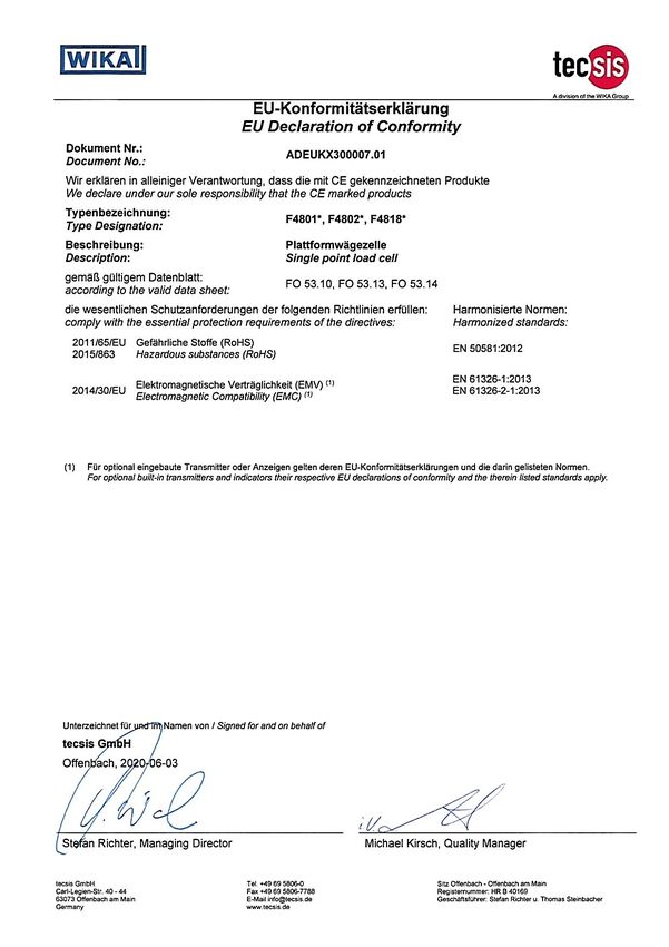
9.1 Approvals
Logo Description Country
ADPR1X914110.01 07/2021 EN/DE
EU declaration of conformity European Union
■ EMC directive
■ RoHS directive
EAC Eurasian Economic Community
■ EMC directive
WIKA operating instructions, models F4801, F4802, F4818 2110. Accessories
10. Accessories
WIKA accessories can be found online at www.wika.com.
EN 10.1 Cable
Cable with circular connector M12 x 1
Cable socket M12 x 1 Order number
Length 2 m Length 5 m Length 10 m
4-pin with cable straight EZE53X011010 EZE53X011012 EZE53X011016
angled EZE53X011011 EZE53X011013 EZE53X011017
5-pin with cable straight EZE53X011043 EZE53X011044 EZE53X011047
angled EZE53X011045 EZE53X011046 EZE53X011071
Other cable lengths and cable types are available on request.
10.2 Cable amplifier B1940
Pin assignment with cable amplifier
PE
Ub+ brown DC +24 V
Strain gauge S+ yellow Power supply unit
amplifier 0V green GND
-
Evaluation
Display
+
ADPR1X914110.01 07/2021 EN/DE
■ SG amplifier integrated into the measuring line (cable amplifier)
■ Output signal 0/4 ... 20 mA or DC 0 ... ±10 V or DC 0 ... ±5 V (3-wire)
■ Linearity10. Accessories
10.3 E1932 strain gauge weighing electronics
EN
■ Strain gauge input up to 3 mV/V (4- and 6-wire)
■ Optional 4 … 20 mA / DC 0 … 10 V input (passive)
■ Very well readable LC display (20 mm high digits), backlit, 6-digit, selectable units
g, kg, lb or t
■ Function buttons: Zero, Tare, Gross/Net, Print
■ E1932X200 with additional function buttons, programmable for one of the integrated
functions (count, hold, hold peak value, live weighing, summing)
■ 2 limit value contacts (from E1932X200)
■ Integrated RS-232 interface (from E1932X200)
■ Optional 4 … 20 mA / DC 0 … 10 V output (in place of RS-232) (from E1932X200/
E1932X300)
■ Configurable print format in combination with date/hour (from E1932X200)
■ 1 control input for remote operation (from E1932X200)
■ Different case variants: Panel mounting, table or wall-mounting case (up to IP65)
■ AC, DC and battery or rechargeable battery operation
■ Wide-band DC operation (DC 7 ... 24 V)
■ Battery/rechargeable battery option possible (DC 4.8 ... 24 V) – optimal for a number
of mobile applications
10.4 B6578 junction box
ADPR1X914110.01 07/2021 EN/DE
■ 4-channel
■ Rugged stainless steel case
■ Cable connection via clamps
■ IP67
WIKA operating instructions, models F4801, F4802, F4818 2310. Accessories
10.5 Large display for mA or V signals E1931X800
EN
■ SG large display with LED display for panel mounting
■ LED 5-digit, 100 mm high, red, readable from 50 m
■ For input signals 0/4 ... 20 mA 2- or 3-wire and DC 0 ... 10 V
■ Freely programmable via remote button control
■ 2 or 4 freely programmable limit value contacts
■ Freely programmable analogue output (0/4 ... 20 mA / DC 0 ... 10 V)
■ Digital output signal over RS-232 or RS-485 serial interface
■ 3 logic inputs for remote control
■ Limit frequency up to 5 Hz for quasi static applications
■ Accuracy 0.03 % of full scale
■ Up to 4 strain gauge sensors with 350 Ohm can be connected in parallel
■ Bridge supply 5 or 10 VDC
■ Required supply voltage AC 85 ... 250 V
■ Operator and service-friendly due to large screw terminals, remote button operation
and LED display
■ IP65 ingress protection from the front when built in
■ Optional with robust surround case with IP65
ADPR1X914110.01 07/2021 EN/DE
24 WIKA operating instructions, models F4801, F4802, F4818Annex: EU declaration of conformity
EN
ADPR1X914110.01 07/2021 EN/DE
WIKA operating instructions, models F4801, F4802, F4818 25EN
ADPR1X914110.01 07/2021 EN/DE
26 WIKA operating instructions, models F4801, F4802, F4818Inhalt
Inhalt
1. Allgemeines 28
2. Aufbau und Funktion 29
2.1 Übersicht . . . . . . . . . . . . . . . . . . . . . . . 29
2.2 Beschreibung . . . . . . . . . . . . . . . . . . . . . 29
2.3 Lieferumfang . . . . . . . . . . . . . . . . . . . . . . 29
3. Sicherheit 30 DE
3.1 Symbolerklärung . . . . . . . . . . . . . . . . . . . . 30
3.2 Bestimmungsgemäße Verwendung . . . . . . . . . . . . . . 30
3.3 Fehlgebrauch . . . . . . . . . . . . . . . . . . . . . 31
3.4 Verantwortung des Betreibers . . . . . . . . . . . . . . . . 31
3.5 Personalqualifikation . . . . . . . . . . . . . . . . . . . 32
3.6 Persönliche Schutzausrüstung . . . . . . . . . . . . . . . 32
3.7 Beschilderung, Sicherheitskennzeichnungen . . . . . . . . . . . 33
4. Transport, Verpackung und Lagerung 34
4.1 Transport . . . . . . . . . . . . . . . . . . . . . . . 34
4.2 Verpackung und Lagerung . . . . . . . . . . . . . . . . . 34
5. Inbetriebnahme, Betrieb 35
5.1 Montagevorbereitung . . . . . . . . . . . . . . . . . . . 35
5.2 Montagehinweise . . . . . . . . . . . . . . . . . . . . 35
5.3 Montage der Plattformwägezelle . . . . . . . . . . . . . . . 36
5.4 Elektrischer Anschluss . . . . . . . . . . . . . . . . . . 37
6. Störungen 38
7. Wartung und Reinigung 38
7.1 Wartung . . . . . . . . . . . . . . . . . . . . . . . 38
7.2 Reinigung . . . . . . . . . . . . . . . . . . . . . . . 38
8. Demontage, Rücksendung und Entsorgung 39
8.1 Demontage . . . . . . . . . . . . . . . . . . . . . . 39
8.2 Rücksendung . . . . . . . . . . . . . . . . . . . . . 39
8.3 Entsorgung . . . . . . . . . . . . . . . . . . . . . . 39
9. Technische Daten 40
9.1 Zulassungen . . . . . . . . . . . . . . . . . . . . . . 45
10. Zubehör 46
10.1 Kabel . . . . . . . . . . . . . . . . . . . . . . . . 46
ADPR1X914110.01 07/2021 EN/DE
10.2 Kabelmessverstärker B1940 . . . . . . . . . . . . . . . . 46
10.3 DMS-Wägeelektronik E1932 . . . . . . . . . . . . . . . . 47
10.4 Anschlusskasten B6578 . . . . . . . . . . . . . . . . . 47
10.5 Großanzeige für mA- oder V-Signale E1931X800 . . . . . . . . . 48
Anlage: EU-Konformitätserklärung 49
WIKA Betriebsanleitung, Typen F4801, F4802, F4818 271. Allgemeines
1. Allgemeines
■ Die in der Betriebsanleitung beschriebenen Plattformwägezellen werden nach dem
aktuellen Stand der Technik konstruiert und gefertigt. Alle Komponenten unter-
liegen während der Fertigung strengen Qualitäts- und Umweltkriterien. Unsere
Managementsysteme sind nach ISO 9001 zertifiziert.
■ Diese Betriebsanleitung gibt wichtige Hinweise zum Umgang mit dem Gerät.
DE
Voraussetzung für sicheres Arbeiten ist die Einhaltung aller angegebenen
Sicherheitshinweise und Handlungsanweisungen.
■ Die für den Einsatzbereich des Gerätes geltenden örtlichen
Unfallverhütungsvorschriften und allgemeinen Sicherheitsbestimmungen einhalten.
■ Die Betriebsanleitung ist Produktbestandteil und muss in unmittelbarer Nähe des
Gerätes für das Fachpersonal jederzeit zugänglich aufbewahrt werden. Betriebsan-
leitung an nachfolgende Benutzer oder Besitzer des Gerätes weitergeben.
■ Das Fachpersonal muss die Betriebsanleitung vor Beginn aller Arbeiten sorgfältig
durchgelesen und verstanden haben.
■ Es gelten die allgemeinen Geschäftsbedingungen in den Verkaufsunterlagen.
■ Technische Änderungen vorbehalten.
Weitere Informationen:
- Internet-Adresse: www.wika.de
- Zugehöriges Datenblatt: FO 53.10 (Typ F4801)
FO 53.13 (Typ F4802)
FO 53.14 (Typ F4818)
- Anwendungsberater: Tel.: +49 9372 132-0
Fax: +49 9372 132-406
info@wika.de
Abkürzungen, Definitionen
4-Leiter Zwei Anschlussleitungen zur Spannungsversorgung
Eine Anschlussleitung für das Messsignal
UB+ Positiver Versorgungsanschluss
UB- Negativer Versorgungsanschluss
S+ Positiver Messanschluss
S- Negativer Messanschluss
Schirm Gehäuse
ADPR1X914110.01 07/2021 EN/DE
DMS Dehnungsmessstreifen
28 WIKA Betriebsanleitung, Typen F4801, F4802, F48182. Aufbau und Funktion
2. Aufbau und Funktion
2.1 Übersicht
Krafteinleitung
Messfeder
Elektrischer Anschluss DE
F
F
2.2 Beschreibung
Die Plattformwägezelle ist für das Messen statischer Druckkräfte in wägetechnischen
Anwendungen vorgesehen. Die Plattformwägezelle besteht aus einer Messfeder auf der
vier Dehnungsmessstreifen (DMS) aufgebracht sind. Der Messköper ist aus Aluminium
gefertigt und wird durch in die Kraftrichtung eingeleitete Kraft elastisch verformt. Die
enstehenden mechanischen Spannungen werden dabei durch die Dehnungsmessstrei-
fen gemessen und als elektrisches Ausgangssignal ausgegeben.
Die DMS sind so angeordnet, dass zwei von ihnen gedehnt und die beiden anderen
gestaucht werden, wenn eine Kraft auf die Plattformwägezelle einwirkt.
Die Plattformwägezellenschaltung enthält Korrektur- und Kompensationswiderstände,
ADPR1X914110.01 07/2021 EN/DE
um unerwünschte Einflüsse auf Nullsignal und Kennwert zu beseitigen.
2.3 Lieferumfang
■ Plattformwägezelle
■ Betriebsanleitung
WIKA Betriebsanleitung, Typen F4801, F4802, F4818 293. Sicherheit
3. Sicherheit
3.1 Symbolerklärung
WARNUNG!
... weist auf eine möglicherweise gefährliche Situation hin, die zum Tod
DE oder zu schweren Verletzungen führen kann, wenn sie nicht gemieden
wird.
VORSICHT!
... weist auf eine möglicherweise gefährliche Situation hin, die zu geringfü-
gigen oder leichten Verletzungen bzw. Sach- und Umweltschäden führen
kann, wenn sie nicht gemieden wird.
Information
... hebt nützliche Tipps und Empfehlungen sowie Informationen für einen
effizienten und störungsfreien Betrieb hervor.
3.2 Bestimmungsgemäße Verwendung
Die Plattformwägezellen sind für das Messen statischer Kräfte vorgesehen.
Typ Ausführung/Messbereiche
F4801 0 … 3 kg bis 0 ... 250 kg
F4802 0 … 0,3 kg bis 0 ... 10 kg
F4818 0 … 20 kg bis 0 ... 500 kg
Diese Geräte sind gemäß den Sicherheitsbestimmungen für elektronische Messgeräte
ADPR1X914110.01 07/2021 EN/DE
gebaut und geprüft. Jeder darüber hinausgehende Gebrauch gilt als nicht bestim-
mungsgemäß. Die einwandfreie Funktion und Betriebssicherheit der Plattformwägezelle
kann nur bei Einhaltung der Angaben in der Betriebsanleitung garantiert werden. Bei
der Verwendung sind zusätzlich die für den jeweiligen Anwendungsfall erforderlichen
Rechts- und Sicherheitsvorschriften zu beachten (z. B. VDE 0100). Sinngemäß gilt dies
auch bei Verwendung von Zubehör. Der einwandfreie und sichere Betrieb dieser Platt-
formwägezelle setzt sachgemäßen Transport, fachgerechte Lagerung, Aufstellung und
Montage sowie sorgfältige Bedienung und Instandhaltung voraus.
30 WIKA Betriebsanleitung, Typen F4801, F4802, F48183. Sicherheit
Das Gerät ist ausschließlich für den hier beschriebenen bestimmungsgemäßen Verwen-
dungszweck konzipiert und konstruiert und darf nur dementsprechend verwendet
werden. Die technischen Spezifikationen in dieser Betriebsanleitung sind einzuhalten.
Eine unsachgemäße Handhabung oder ein Betreiben des Gerätes außerhalb der
technischen Spezifikationen macht die sofortige Stilllegung und Überprüfung durch
einen autorisierten Servicemitarbeiter erforderlich.
Elektronische Präzisionsmessgeräte mit erforderlicher Sorgfalt behandeln (vor Nässe, DE
Stößen, starken Magnetfeldern, statischer Elektrizität und extremen Temperaturen
schützen, keine Gegenstände in das Gerät bzw. Öffnungen einführen). Stecker und
Buchsen vor Verschmutzung schützen.
Ansprüche jeglicher Art aufgrund von nicht bestimmungsgemäßer Verwendung sind
ausgeschlossen.
3.3 Fehlgebrauch
WARNUNG!
Verletzungen durch Fehlgebrauch
Fehlgebrauch des Gerätes kann zu gefährlichen Situationen und
Verletzungen führen.
▶ Eigenmächtige Umbauten am Gerät unterlassen.
Jede über die bestimmungsgemäße Verwendung hinausgehende oder andersartige
Benutzung gilt als Fehlgebrauch.
3.4 Verantwortung des Betreibers
Das Gerät wird im gewerblichen Bereich eingesetzt. Der Betreiber unterliegt daher den
gesetzlichen Pflichten zur Arbeitssicherheit.
Die Sicherheitshinweise dieser Betriebsanleitung, sowie die für den Einsatzbereich des
Gerätes gültigen Sicherheits-, Unfallverhütungs- und Umweltschutzvorschriften einhalten.
Der Betreiber ist verpflichtet das Typenschild lesbar zu halten.
Für ein sicheres Arbeiten am Gerät muss der Betreiber sicherstellen,
ADPR1X914110.01 07/2021 EN/DE
■ dass eine entsprechende Erste-Hilfe-Ausrüstung vorhanden ist und bei Bedarf jeder-
zeit Hilfe zur Stelle ist.
■ dass das Elektrofachpersonal regelmäßig in allen zutreffenden Fragen von Arbeits-
sicherheit, Erste Hilfe und Umweltschutz unterwiesen wird, sowie die Betriebsanlei-
tung und insbesondere die darin enthaltenen Sicherheitshinweise kennt.
■ dass das Gerät gemäß der bestimmungsgemäßen Verwendung für den
Anwendungsfall geeignet ist.
■ dass die persönliche Schutzausrüstung verfügbar ist.
WIKA Betriebsanleitung, Typen F4801, F4802, F4818 313. Sicherheit
3.5 Personalqualifikation
WARNUNG!
Verletzungsgefahr bei unzureichender Qualifikation
Unsachgemäßer Umgang kann zu erheblichen Personen- und Sachschä-
den führen.
▶ Die in dieser Betriebsanleitung beschriebenen Tätigkeiten nur durch
DE Fachpersonal nachfolgend beschriebener Qualifikation durchführen
lassen.
Elektrofachpersonal
Das Elektrofachpersonal ist aufgrund seiner fachlichen Ausbildung, Kenntnisse und
Erfahrungen sowie Kenntnis der landesspezifischen Vorschriften, geltenden Normen
und Richtlinien in der Lage, Arbeiten an elektrischen Anlagen auszuführen und
mögliche Gefahren selbstständig zu erkennen und zu vermeiden. Das Elektrofachper-
sonal ist speziell für das Arbeitsumfeld, in dem es tätig ist, ausgebildet und kennt die
relevanten Normen und Bestimmungen. Das Elektrofachpersonal muss die Bestimmun-
gen der geltenden gesetzlichen Vorschriften zur Unfallverhütung erfüllen.
3.6 Persönliche Schutzausrüstung
Anforderungen an benötigte Schutzausrüstung ergeben sich aus den
Umgebungsbedingungen am Ort der Nutzung, anderen Produkten oder der
Verknüpfung mit anderen Produkten.
Die erforderliche persönliche Schutzausrüstung muss vom Betreiber zur Verfügung
gestellt werden. Der Betreiber wird durch diese Vorschläge in keinster Weise von seinen
arbeitsrechtlichen Pflichten zur Sicherheit und dem Schutz der Gesundheit der Arbeit-
nehmer entbunden.
Die Bemessung der persönlichen Schutzausrüstung muss unter Berücksichtigung aller
Betriebsparameter des Einsatzortes erfolgen.
ADPR1X914110.01 07/2021 EN/DE
32 WIKA Betriebsanleitung, Typen F4801, F4802, F48183. Sicherheit
3.7 Beschilderung, Sicherheitskennzeichnungen
Typenschild
DE
11
Typ
Herstellerlogo
Seriennummer
Schutzart gem. DIN EN 60259
Anschlussbelegung
Herstelleradresse
Kraftrichtung
Speisespannung
Ausgangssignal
Messbereich
11 Produktcode
ADPR1X914110.01 07/2021 EN/DE
WIKA Betriebsanleitung, Typen F4801, F4802, F4818 334. Transport, Verpackung und Lagerung
4. Transport, Verpackung und Lagerung
4.1 Transport
Die Plattformwägezelle auf eventuell vorhandene Transportschäden untersuchen. Offen-
sichtliche Schäden unverzüglich mitteilen.
DE VORSICHT!
Beschädigungen durch unsachgemäßen Transport
Bei unsachgemäßem Transport können Sachschäden in erheblicher Höhe
entstehen.
▶ Beim Abladen der Packstücke bei Anlieferung sowie innerbetrieblichem
Transport vorsichtig vorgehen und die Symbole auf der Verpackung
beachten.
▶ Bei innerbetrieblichem Transport die Hinweise unter Kapitel 4.2
„Verpackung und Lagerung“ beachten.
Als Präzisionsmessgeräte verlangen die Plattformwägezellen beim Transport und
der Montage eine sorgfältige Handhabung. Laststöße während des Transports
(z. B. Aufschlag auf harten Untergrund) können zu bleidenden Schäden führen, die im
späteren Messbetrieb zu Messfehlern führen.
4.2 Verpackung und Lagerung
Verpackung erst unmittelbar vor der Montage entfernen.
Die Verpackung aufbewahren, denn diese bietet bei einem Transport einen optimalen
Schutz (z. B. wechselnder Einbauort, Reparatursendung).
Die Messfeder ist vollständig aus Aluminium hergestellt und entspricht der Schutzart IP65.
Zulässige Bedingungen am Lagerort:
■ Lagertemperatur: -20 ... +60 °C
■ Feuchtigkeit: 35 ... 85 % relative Feuchte (keine Betauung)
Folgende Einflüsse vermeiden:
■ Mechanische Vibration, mechanischer Schock (hartes Aufstellen)
■ Staub, Schmutz und sonstige Gegenstände dürfen sich nicht so ablagern, dass
sie einen Kraftnebenschluss zur Messfeder bilden, da dadurch das Messsignal
verfälscht wird.
ADPR1X914110.01 07/2021 EN/DE
34 WIKA Betriebsanleitung, Typen F4801, F4802, F48185. Inbetriebnahme, Betrieb
5. Inbetriebnahme, Betrieb
5.1 Montagevorbereitung
■ Plattformwägezellen sind empfindliche Messgeräte und entsprechend sorgsam zu
behandeln.
■ Bei der Inbetriebnahme der Plattformwägezelle muss auf eine ebene, saubere und
fettfreie Montagefläche geachtet werden. DE
5.2 Montagehinweise
VORSICHT!
Beschädigung des Gerätes durch unsachgemäße Inbetriebnahme
■ Die Krafteinleitung erfolgt über eine auf die Plattformwägezelle
montierte Plattform. Die Last kann auf dieser Plattform beliebig
positioniert werden. Auf die Plattformgröße ist zu achten, siehe Kapitel
9 „Technische Daten“.
■ Zu hohe Torsions- und Querkräfte sind zu vermeiden. Torsionsmomente
und Querbelastungen bzw. Seitenkräfte verursachen Messfehler und
können die Plattformwägezelle bleibend schädigen.
■ Während des Einbaus der Plattformwägezelle ist das Ausgangssignal
(Kraftwert) stets zu überwachen, um eine mechanische Überlastung zu
vermeiden.
■ Die Plattformwägezelle darf nur in der vorgesehenen Belastungsrich-
tung belastet werden, siehe Kapitel 3 „Typenschild“.
■ Fehlbelastungen in die falsche Belastungsrichtung können die
Plattformwägezelle bleibend schädigen.
■ Eine Überlastung ist zu jeder Zeit auszuschließen.
■ Bei der Montage darauf achten, dass die Plattformwägezelle genügend
Federweg hat, siehe Kapitel 5.3 „Montage“. Gegebenenfalls Distanz-
stücke verwenden.
■ Das max. Drehmoment zur Befestigung der Plattformwägezelle ist zu
beachten, siehe Kapitel 9 „Technische Daten“.
■ Gegebenenfalls ist bei der Montage der Wägezelle ein Anschlag als
Überlastschutz zu verwenden.
ADPR1X914110.01 07/2021 EN/DE
WIKA Betriebsanleitung, Typen F4801, F4802, F4818 355. Inbetriebnahme, Betrieb
5.3 Montage der Plattformwägezelle
= =
= =
DE
Plattformwägezelle
Montagefläche
Plattform
Distanzstück
Federweg
■ Die Unterseite der Plattformwägezelle mit der Montagefläche verschrauben und
dabei darauf achten, dass die gegenüberliegende Seite der Plattformwägezelle nicht
auf der Montagefläche aufliegt (kein Kraftnebenschluss).
■ Gegebenenfalls Distanzstücke verwenden. Die Dicke des Distanzstücks entspricht
dem Federweg .
■ Die Plattform so ausrichten, dass die Mitte der Plattform der Mitte der Plattformwä-
ADPR1X914110.01 07/2021 EN/DE
gezelle entspricht.
■ Die Oberseite der Plattformwägezelle mit der Plattform verschrauben und dabei
darauf achten, dass die gegenüberliegende Seite der Plattformwägezelle keinen
Kontakt mit der Plattform hat (kein Kraftnebenschluss).
■ Gegebenenfalls Distanzstücke verwenden.
36 WIKA Betriebsanleitung, Typen F4801, F4802, F48185. Inbetriebnahme, Betrieb
5.4 Elektrischer Anschluss
Um Einkopplungen von Störungen zu vermeiden, sind folgende Hinweise zu
beachten:
■ Ein abgeschirmtes, kapazitätsarmes Messkabel ist an der Plattformwägezelle
angebaut.
■ Den Schirm des Messkabels erden.
■ Streufelder von Transformatoren sowie Motoren und Schützen vermeiden.
DE
■ Beim Verlängern dürfen nur abgeschirmte und kapazitätsarme Kabel verwendet
werden. Die erlaubten maximalen und minimalen Längen des Kabels sind in der
ISO 11898-2 angegeben. Dabei ist auf eine hochwertige Verbindung auch der
Abschirmung zu achten.
■ Messkabel nicht parallel zu Starkstrom- und Steuerleitungen legen.
■ Plattformwägezelle, Verstärker und Verarbeitungs- bzw. Anzeigeeinheit dürfen nicht
mehrfach geerdet werden.
Die Anschlussbelegung des Kabels sind dem Typenschild zu entnehmen.
5.4.1 Anschlussbelegung Kabel
Elektrischer Anschluss
Hilfsenergie (+) UB+ bzw. E+ Rot
Hilfsenergie (-) UB- bzw. E- Schwarz
Signal (+) S+ Grün
Signal (-) S- Weiß
Schirm Schirm Schirm
Exc+
UB+ (Rot)
Sig+
S+ (Grün)
ADPR1X914110.01 07/2021 EN/DE
UB- (Schwarz)
Exc-
S- (Weiß)
Sig-
(Schirm)
WIKA Betriebsanleitung, Typen F4801, F4802, F4818 376. Störungen / 7. Wartung und Reinigung
6. Störungen
VORSICHT!
Körperverletzungen, Sachschäden
Können Störungen mit Hilfe der aufgeführten Maßnahmen nicht beseitigt
werden, die Plattformwägezelle unverzüglich außer Betrieb setzen.
▶ Kontakt mit dem Hersteller aufnehmen.
DE
▶ Bei notwendiger Rücksendung die Hinweise unter Kapitel 8.2
„Rücksendung“ beachten.
Kontaktdaten siehe Kapitel 1 „Allgemeines“ oder Rückseite der Betriebs-
anleitung.
Störungen Ursachen Maßnahmen
Kein Ausgangssignal Keine oder falsche Hilfsenergie, Hilfsenergie korrigieren
Stromstoß
Leitungsbruch Durchgang überprüfen
Kein oder falsches Falsche Kabelbelegung Kabelbelegung prüfen
Ausgangssignal
Abweichendes Nullpunkt- Überlast, Last-Offset, falscher Rücksprache mit Hersteller
Signal Anschluss
Abweichendes Ausgangssignal Kabel zu lang Rücksprache mit Hersteller
Gleichbleiben des Ausgangssi- Falsche Kabelbelegung Kabelbelegung prüfen
gnals bei Kraftänderung Mechanische Überlastung Rücksprache mit Hersteller
Signalspanne fällt ab/zu klein Mechanische Überlastung Rücksprache mit Hersteller
Defekte Geräte sind an den Hersteller zurückzusenden.
7. Wartung und Reinigung
Kontaktdaten siehe Kapitel 1 „Allgemeines“ oder Rückseite der Betriebs-
anleitung.
ADPR1X914110.01 07/2021 EN/DE
7.1 Wartung
Dieses Gerät ist wartungsfrei.
Reparaturen sind ausschließlich vom Hersteller durchzuführen.
Nur Originalteile verwenden (siehe Kapitel 10 „Zubehör”).
7.2 Reinigung
1. Vor der Reinigung die Plattformwägezelle ordnungsgemäß von
Spannungsversorgung trennen und ausbauen.
38 WIKA Betriebsanleitung, Typen F4801, F4802, F48187. Wartung und Reinigung / 8. Demontage, Rücksendung..
2. Die Plattformwägezelle mit einem Tuch reinigen.
Elektrische Anschlüsse nicht mit Feuchtigkeit in Berührung bringen!
VORSICHT!
Beschädigung des Gerätes
Eine unsachgemäße Reinigung führt zur Beschädigung des Gerätes!
▶ Keine aggressiven Reinigungsmittel verwenden.
▶ Keine harten und spitzen Gegenstände zur Reinigung verwenden. DE
8. Demontage, Rücksendung und Entsorgung
8.1 Demontage
Die Plattformwägezelle entlasten, vom Strom trennen und aus der Montagesituation
entfernen.
8.2 Rücksendung
Beim Versand des Gerätes unbedingt beachten:
Alle an WIKA gelieferten Geräte müssen frei von Gefahrstoffen (Säuren, Laugen,
Lösungen, etc.) sein und sind daher vor der Rücksendung zu reinigen.
Zur Rücksendung des Gerätes die Originalverpackung oder eine geeignete
Transportverpackung verwenden.
Um Schäden zu vermeiden:
1. Das Gerät in eine antistatische Plastikfolie einhüllen.
2. Das Gerät mit dem Dämmmaterial in der Verpackung platzieren.
Zu allen Seiten der Transportverpackung gleichmäßig dämmen.
3. Wenn möglich einen Beutel mit Trocknungsmittel der Verpackung beifügen.
4. Sendung als Transport eines hochempfindlichen Messgerätes kennzeichnen.
Hinweise zur Rücksendung befinden sich in der Rubrik „Service“ auf
unserer lokalen Internetseite.
8.3 Entsorgung
Durch falsche Entsorgung können Gefahren für die Umwelt entstehen.
Gerätekomponenten und Verpackungsmaterialien entsprechend den
ADPR1X914110.01 07/2021 EN/DE
landesspezifischen Abfallbehandlungs- und Entsorgungsvorschriften umweltgerecht
entsorgen.
Nicht mit dem Hausmüll entsorgen. Für eine geordnete Entsorgung
gemäß nationaler Vorgaben sorgen.
WIKA Betriebsanleitung, Typen F4801, F4802, F4818 399. Technische Daten
9. Technische Daten
Typ F4801
Nennlast Fnom 3 / 4 / 5 / 6 / 8 / 10 / 15 / 20 / 25 / 30 / 40 / 45 /
50 / 60 / 100 / 150 / 200 / 250 kg
DE Relative Linearitätsabweichung dlin ±0,02 % Fnom
Relatives Kriechen, 30 min. ±0,02 % Fnom
Relative Umkehrspanne v ±0,02 % Fnom
Relative Abweichung des Nullsignals dS, 0 ±2 % Fnom
Temperatureinfluss auf das Nullsignal TK0 ≤ ±0,02 %/10 °C
Temperatureinfluss auf den Kennwert TKC ≤ ±0,02 %/10 °C
Grenzkraft FL 150 % Fnom
Bruchkraft FB 200 % Fnom
Werkstoff des Messkörpers Aluminium
Nenntemperaturbereich BT, nom -10 … +40 °C
Gebrauchstemperaturbereich BT, G -20 … +60 °C
Eingangswiderstand Re 410 ± 10 Ω
Ausgangswiderstand Ra 350 ± 5 Ω
Isolationswiderstand Ris ≥ 2.000 MΩ/DC 100 V
Ausgangssignal (Nennkennwert) Cnom 2,0 ± 1 % mV/V
Elektrischer Anschluss Messkabel Ø 3 x 450 mm
Hilfsenergie BU, nom DC 10 V (max. 15 V)
Schutzart (nach IEC/EN 60529) IP65
Plattformgröße max. 250 x 300 mm
Gewicht
3 bis 50 kg 0,3 kg
60 bis 250 kg 0,4 kg
ADPR1X914110.01 07/2021 EN/DE
40 WIKA Betriebsanleitung, Typen F4801, F4802, F4818Abmessungen Typ F4801
DE
Nennlast in kg Maße in mm
A B C D L M Anzugsmoment
3 / 4 / 5 / 6 / 8 / 10 / 15 / 20 130 30 106 22 15 M6 10 Nm
/ 25 / 30 / 40 / 45 / 50
60 / 100 / 150 / 200 / 250 130 50 106 22 25 M8 24 Nm
ADPR1X914110.01 07/2021 EN/DE
WIKA Betriebsanleitung, Typen F4801, F4802, F4818 419. Technische Daten
Typ F4802
Nennlast Fnom 0,3 / 0,5 / 1 / 1,5 / 2 / 3 / 4 / 5 / 10 kg
Relative Linearitätsabweichung dlin ±0,02 % Fnom
Relative Umkehrspanne v ±0,02 % Fnom
Relative Spannweite in unveränderter ±0,02 % Fnom
DE Einbaulage brg
Relative Abweichung des Nullsignals dS, 0 ±2 % Fnom
Relatives Kriechen, 30 min. ±0,02 % Fnom
Temperatureinfluss auf das Nullsignal TK0 ≤ ±0,025 %/10 °C
Temperatureinfluss auf den Kennwert TKC ≤ ±0,025 %/10 °C
Grenzkraft FL 150 % Fnom
Bruchkraft FB 200 % Fnom
Werkstoff des Messkörpers Aluminium
Nenntemperaturbereich BT, nom -10 … +40 °C
Gebrauchstemperaturbereich BT, G -20 … +60 °C
Eingangswiderstand Re 410 ± 10 Ω
Ausgangswiderstand Ra 350 ± 5 Ω
Isolationswiderstand Ris ≥ 2.000 MΩ/DC 100 V
Ausgangssignal (Nennkennwert) Cnom 2,0 ± 1 % mV/V
Elektrischer Anschluss Messkabel Ø 3 x 450 mm
Hilfsenergie BU, nom DC 10 V (max. 15 V)
Schutzart (nach IEC/EN 60529) IP65
Plattformgröße max. 200 x 200 mm
Gewicht 0,1 kg
ADPR1X914110.01 07/2021 EN/DE
42 WIKA Betriebsanleitung, Typen F4801, F4802, F48189. Technische Daten
Abmessungen Typ F4802
DE
22
450
M3(4x)
15
7
58
70
Anzugsmoment für M3: 1 Nm Maße in mm
ADPR1X914110.01 07/2021 EN/DE
WIKA Betriebsanleitung, Typen F4801, F4802, F4818 439. Technische Daten
Typ F4818
Nennlast Fnom kg 20, 30, 50, 60, 100, 150, 200, 250, 300, 350, 500
Relative Linearitätsabweichung dlin ±0,02 % Fnom
Relatives Kriechen, 30 min. ±0,02 % Fnom
Relative Umkehrspanne v ±0,02 % Fnom
DE Relative Abweichung des Nullsignals dS, 0 ±2 % Fnom
Temperatureinfluss auf das Nullsignal TK0 ≤ ±0,025 %/10 °C
Temperatureinfluss auf den Kennwert TKC ≤ ±0,025 %/10 °C
Grenzkraft FL 120 % Fnom
Bruchkraft FB 200 % Fnom
Werkstoff des Messkörpers Aluminium
Nenntemperaturbereich BT, nom -10 … +40 °C
Gebrauchstemperaturbereich BT, G -20 … +60 °C
Eingangswiderstand Re 410 ± 10 Ω
Ausgangswiderstand Ra 350 ± 5 Ω
Isolationswiderstand Ris ≥ 2.000 MΩ/DC 100 V
Ausgangssignal (Nennkennwert) Cnom 2,0 ± 10 % mV/V
Elektrischer Anschluss Messkabel Ø 5 x 1.500 mm
Hilfsenergie BU, nom 10 V (max. 15 V)
Schutzart (nach IEC/EN 60529) IP65
Plattformgröße max. 450 x 450 mm
Gewicht in kg 0,6
ADPR1X914110.01 07/2021 EN/DE
44 WIKA Betriebsanleitung, Typen F4801, F4802, F48189. Technische Daten
Abmessungen Typ F4818
DE
24
40
150 1500
117
M6(8x)
35
15
7 19
Anzugsmoment für M6: 10 Nm Maße in mm
9.1 Zulassungen
Logo Beschreibung Land
EU-Konformitätserklärung Europäische Union
ADPR1X914110.01 07/2021 EN/DE
■ EMV-Richtlinie
■ RoHS-Richtlinie
EAC Eurasische Wirtschaftsgemeischaft
■ EMV-Richtlinie
WIKA Betriebsanleitung, Typen F4801, F4802, F4818 4510. Zubehör
10. Zubehör
WIKA-Zubehör finden Sie online unter www.wika.de.
10.1 Kabel
Kabel mit Rundstecker M12 x 1
DE Kabeldose M12 x 1 Bestellnummer
Länge 2 m Länge 5 m Länge 10 m
4-polig mit Kabel gerade EZE53X011010 EZE53X011012 EZE53X011016
gewinkelt EZE53X011011 EZE53X011013 EZE53X011017
5-polig mit Kabel gerade EZE53X011043 EZE53X011044 EZE53X011047
gewinkelt EZE53X011045 EZE53X011046 EZE53X011071
Andere Kabellängen und Kabelarten sind auf Anfrage erhältlich.
10.2 Kabelmessverstärker B1940
Pinbelegung mit Kabelmessverstärker
PE
Ub+ braun DC +24 V
DMS-Messver- S+ gelb Netzteil
stärker 0V grün GND
-
Auswertung
Anzeige
+
ADPR1X914110.01 07/2021 EN/DE
■ DMS-Messverstärker in Messleitung integriert (Kabelmessverstärker)
■ Ausgangssignale 0/4 ... 20 mA oder DC 0 ... ±10 V oder DC 0 ... ±5 V (3-Leiter)
■ Linearität10. Zubehör
10.3 DMS-Wägeelektronik E1932
DE
■ DMS-Eingang bis 3 mV/V (4- und 6-Leiter)
■ Optional 4 … 20 mA / DC 0 … 10 V Eingang (passiv)
■ Sehr gut ablesbare LC-Anzeige (20 mm hohe Digits), beleuchtet, 6-stellig, Einheit
g, kg, lb oder t wählbar
■ Funktionstasten: Nullen, Tara, Brutto/Netto, Drucken
■ E1932X200 mit zusätzlicher Funktionstaste, programmierbar für eine der integrier-
ten Funktionen (Zählen, Halten, Spitzenwert halten, Lebendgewichtverwiegung,
Summierung)
■ 2 Grenzwertkontakte (ab E1932X200)
■ Integrierte RS-232-Schnittstelle (ab E1932X200)
■ Optional 4 … 20 mA / DC 0 … 10 V Ausgang (statt RS-232) (ab E1932X200/
E1932X300)
■ Konfigurierbares Druckformat in Kombination mit Datum/Uhrzeit (ab E1932X200)
■ 1 Steuereingang zur Fernbedienung (ab E1932X200)
■ Verschiedene Gehäusevarianten: Schalttafeleinbau, Tisch- oder Wandgehäuse
möglich (bis IP65)
■ AC, DC und Batterie- oder Akkubetrieb
■ Weitreichender DC-Betrieb (DC 7 ... 24 V)
■ Batterie-/Akkubetrieb möglich (DC 4,8 ... 24 V) – optimal für eine Vielzahl von mobilen
Anwendungen
10.4 Anschlusskasten B6578
ADPR1X914110.01 07/2021 EN/DE
■ 4-kanalig
■ Stabiles CrNi-Stahl-Gehäuse
■ Kabelanschluss über Klemmen
■ IP67
WIKA Betriebsanleitung, Typen F4801, F4802, F4818 4710. Zubehör
10.5 Großanzeige für mA- oder V-Signale E1931X800
DE
■ DMS-Großanzeige mit LED-Display für Schalttafeleinbau
■ LED 5-stellig, 100 mm hoch, rot, aus 50 m ablesbar
■ Für Eingangssignale 0/4 ... 20 mA 2- oder 3-Leiter und 0 ... 10 V
■ Über Tastenfernbedienung frei programmierbar
■ 2 oder 4 frei programmierbare Grenzwertkontakte
■ Frei programmierbarer Analogausgang (0/4 ... 20 mA / 0 ... 10 V)
■ Digitales Ausgangssignal über serielle RS-232 oder RS-485-Schnittstelle
■ 3 Logikeingänge zur Fernbedienung
■ Grenzfrequenz bis 5 Hz für quasi statische Anwendungen
■ Genauigkeit 0,03 % v. Ew.
■ Bis zu 4 DMS-Sensoren mit 350 Ohm parallel anschliessbar
■ Brückenversorgung DC 5 oder 10 V
■ Benötigte Hilfsenergie AC 85 ... 250 V
■ Bediener- und servicefreundlich durch große Schraubklemmen,
Tastenfernbedienung und LED-Display
■ Schutzart IP65 frontseitig im eingebauten Zustand
■ Optional mit robustem Rundumgehäuse mit IP65 ADPR1X914110.01 07/2021 EN/DE
48 WIKA Betriebsanleitung, Typen F4801, F4802, F4818You can also read