Strain transducer, model F9302 Dehnungsaufnehmer, Typ F9302 - Strain transducer, model F9302 - tecsis
←
→
Page content transcription
If your browser does not render page correctly, please read the page content below

Operating instructions
                           Betriebsanleitung

Strain transducer, model F9302                      EN

Dehnungsaufnehmer, Typ F9302                        DE

         Strain transducer, model F9302
EN Operating instructions model F9302                                     Page              3 - 22

DE Betriebsanleitung Typ F9302                                            Seite           23 - 43

                                                                                                       ADPR1X914022.01 03/2019 EN/DE

  © 03/2019 WIKA Alexander Wiegand SE & Co. KG
  All rights reserved. / Alle Rechte vorbehalten.
  WIKA® and tecsis® are registered trademarks in various countries.
  WIKA® and tecsis® sind geschützte Marken in verschiedenen Ländern.

  Prior to starting any work, read the operating instructions!
  Keep for later use!

  Vor Beginn aller Arbeiten Betriebsanleitung lesen!
  Zum späteren Gebrauch aufbewahren!

   2                                                             Operation instructions, model F9302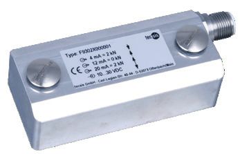
Contents

                                Contents
                                1. General information                                                                                                                 4
                                2. Design and function                                                                                                                 5
                                   2.1 Overview  .   .   .   .   .   .   .   .   .   .   .   .   .   .   .   .   .   .   .   .   .   .   .                             5    EN
                                   2.2 Description . . . . . . . . . . . . . . . . . . . . . . . 5
                                   2.3 Scope of delivery  .  .  .  .  .  .  .  .  .  .  .  .  .  .  .  .  .  .  .  .                                                   5
                                3. Safety                                                                                                                              6
                                   3.1 Explanation of symbols  .  .  .  .  .  .  .  .  .  .  .  .  .  .  .  .  .  .                                                    6
                                   3.2 Intended use  .           .    .    .    .    .    .    .    .    .    .    .    .    .    .    .    .    .    .    .    .    . 6
                                   3.3 Improper use  .   .   .   .   .   .   .   .   .   .   .   .   .   .   .   .   .   .   .   .   .   . 7
                                   3.4 Responsibility of the operator   .   .   .   .   .   .   .   .   .   .   .   .   .   .   .   .                                  7
                                   3.5 Personnel qualification  .   .   .   .   .   .   .   .   .   .   .   .   .   .   .   .   .   .   . 8
                                   3.6 Personal protective equipment  .   .   .   .   .   .   .   .   .   .   .   .   .   .   .   . 8
                                   3.7 Labelling, safety marks  .  .  .  .  .  .  .  .  .  .  .  .  .  .  .  .  .  .                                                   9
                                4. Transport, packaging and storage                                                                                                  10
                                   4.1 Transport  .   .   .   .   .   .   .   .   .   .   .   .   .   .   .   .   .   .   .   .   .   .   . 10
                                   4.2 Packaging and storage  .  .  .  .  .  .  .  .  .  .  .  .  .  .  .  .  .  . 10
                                5. Commissioning, operation                                                                                                          11
                                   5.1 Precautions before commissioning  .  .  .  .  .  .  .  .  .  .  .  .  .  . 11
                                   5.2 Mounting instructions  .                 .    .    .    .    .    .    .    .    .    .    .    .    .    .    .    .    .    . 11
                                   5.3 Installing the strain transducer  .                     .    .    .    .    .    .    .    .    .    .    .    .    .    .    . 12
                                   5.4 Electrical connection   .   .   .   .   .   .   .   .   .   .   .   .   .   .   .   .   .   .   . 13
                                   5.5 Commissioning  .               .    .    .    .    .    .    .    .    .    .    .    .    .    .    .    .    .    .    .    . 14
                                6. Faults                                                                                                                            16
                                7. Maintenance and cleaning                                                                                                          17
                                   7.1 Maintenance  .            .    .    .    .    .    .    .    .    .    .    .    .    .    .    .    .    .    .    .    .    . 17
                                   7.2 Cleaning  .  .  .  .  .  .  .  .  .  .  .  .  .  .  .  .  .  .  .  .  .  .  . 17
                                8. Dismounting, return and disposal                                                                                                  17
                                   8.1 Dismounting  .            .    .    .    .    .    .    .    .    .    .    .    .    .    .    .    .    .    .    .    .    . 17
ADPR1X914022.01 03/2019 EN/DE

                                   8.2 Return  .   .   .   .   .   .   .   .   .   .   .   .   .   .   .   .   .   .   .   .   .   .   .   . 18
                                   8.3 Disposal  .  .  .  .  .  .  .  .  .  .  .  .  .  .  .  .  .  .  .  .  .  .  . 18
                                9. Specifications                                                                                                                    19
                                10. Accessories                                                                                                                      20
                                   10.1 Cable  .       .    .    .    .    .    .    .    .    .    .    .    .    .    .    .    .    .    .    .    .    .    .    . 20
                                11. Appendix: EU declaration of conformity                                                                                           21

                                Operating instructions, model F9302                                                                                                    3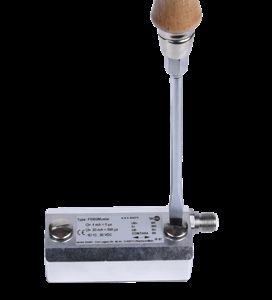
1. General information

     1. General information
     ■■ The strain transducer described in the operating instructions has been designed
          and manufactured using state-of-the-art technology. All components are subject
EN        to stringent quality and environmental criteria during production. Our management
          systems are certified to ISO 9001.

     ■■ These operating instructions contain important information on handling the
          instrument. Working safely requires that all safety instructions and work instructions
          are observed.

     ■■ Observe the relevant local accident prevention regulations and general safety
          regulations for the instrument's range of use.

     ■■ The operating instructions are part of the product and must be kept in the immediate
          vicinity of the instrument and readily accessible to skilled personnel at any time. Pass
          the operating instructions on to the next operator or owner of the instrument.

     ■■ Skilled personnel must have carefully read and understood the operating instructions
          prior to beginning any work.

     ■■ The general terms and conditions contained in the sales documentation shall apply.

     ■■ Subject to technical modifications.

     ■■ Further information:
          - Internet address:            www.wika.de / www.tecsis.de
          - Relevant data sheet:         FO 54.10
          - Application consultant:      Tel.: +49 69 5806-0
                                         Fax: +49 69 5806-7788
                                         info@wika.de, info@tecsis.de

     Abbreviations, definitions

     2-wire        The two connection lines are used for the voltage supply.
                   The measuring signal also provides the supply current.
     3-wire        Two connection lines are used for the voltage supply.
                   One connection line is used for the measuring signal.
     UB+           Positive power supply terminal
                                                                                                     ADPR1X914022.01 03/2019 EN/DE

     UB-           Negative power supply terminal
     S+            Positive output terminal
     S-            Negative output terminal
     Shield        Case
     x-pin         Pin assignment

      4                                                        Operating instructions, model F9302
2. Design and function
2. Design and function
2.1 Overview
Case EN
Electrical connection
Protective caps for M6 Allen screws
Measuring spring
Flat gasket
Mounting screws (M6 Allen screws)
Front side
Rear
2.2 Description
The strain transducer is intended for the measurement of static and dynamic defor-
mations/strains on certain measurement objects. The strain transducer consists of a
measuring spring and a welded thin-film sensor. The measuring body is manufactured
from non-rusting stainless steel and is screwed onto the measurement object. Through
the strains occurring in the measurement object, the measuring spring of the strain
ADPR1X914022.01 03/2019 EN/DE
transducer is elastically deformed. These mechanical deformations are measured by the
installed thin-film sensor and output as an electrical output signal.
2.3 Scope of delivery
■■ Strain transducer
■■ 2 M6 mounting screws (M6 Allen screws)
■■ Operating instructions
Operating instructions, model F9302 53. Safety
3. Safety
3.1 Explanation of symbols
EN
WARNING!
... indicates a potentially dangerous situation that can result in serious
injury or death, if not avoided.
CAUTION!
... indicates a potentially dangerous situation that can result in light injuries
or damage to property or the environment, if not avoided.
Information
... points out useful tips, recommendations and information for efficient
and trouble-free operation.
3.2 Intended use
The strain transducers of the F9302 series are intended for the measurement of static
and dynamic deformations/strains on certain measurement objects.
These instruments have been designed and tested in accordance with the relevant
safety regulations for electronic measuring instruments. Any usage outside of this is
deemed to be improper. The perfect functioning and operational safety of the strain
transducers can only be guaranteed when complying with the instructions given in the
operating instructions. During its use, the legal and safety regulations (e.g. VDE 0100)
required for the particular application must additionally be observed.
This also applies accordingly when using accessories. Strain transducers are RoHS-
compliant in accordance with Directive 2011/65/EU Art. 2 (2) and (4) d), e) and g).
Faultless and safe operation of this transducer requires proper transport, professional
storage, installation and mounting as well as careful operation and corrective mainte-
nance.
The instrument has been designed and built solely for the intended use described here,
ADPR1X914022.01 03/2019 EN/DE
and may only be used accordingly.
The technical specifications contained in these operating instructions must be obser-
ved. Improper handling or operation of the instrument outside of its technical specifica-
tions requires the instrument to be taken out of service immediately and inspected by an
authorised service engineer.
Handle electronic precision measuring instruments with the required care (protect from
6 Operating instructions, model F93023. Safety
humidity, impacts, strong magnetic fields, static electricity and extreme temperatures,
do not insert any objects into the instrument or its openings). Plugs and sockets must be
protected from contamination.
The manufacturer shall not be liable for claims of any type based on operation contrary EN
to the intended use.
3.3 Improper use
WARNING!
Injuries through improper use
Improper use of the instrument can lead to hazardous situations and
injuries.
▶▶ Refrain from unauthorised modifications to the instrument.
Any use beyond or different to the intended use is considered as improper use.
3.4 Responsibility of the operator
The instrument is used in the industrial sector. The operator is therefore responsible for
legal obligations regarding safety at work.
The safety instructions within these operating instructions, as well as the safety,
accident prevention and environmental protection regulations for the application area
must be maintained.
The operator is obliged to maintain the product label in a legible condition.
To ensure safe working on the instrument, the operating company must ensure
■■ that suitable first-aid equipment is available and aid is provided whenever required.
■■ that the skilled electrical personnel are regularly instructed in all topics regarding
work safety, first aid and environmental protection and know the operating instruc-
tions and in particular, the safety instructions contained therein.
■■ that the instrument is suitable for the particular application in accordance with its
ADPR1X914022.01 03/2019 EN/DE
intended use.
■■ that personal protective equipment is available.
Operating instructions, model F9302 73. Safety
3.5 Personnel qualification
WARNING!
Risk of injury should qualification be insufficient
EN Improper handling can result in considerable injury and damage to equip-
ment.
▶▶ The activities described in these operating instructions may only be
carried out by skilled personnel who have the qualifications described
below.
Skilled electrical personnel
Skilled electrical personnel are understood to be personnel who, based on their techni-
cal training, know-how and experience as well as their knowledge of country-specific
regulations, current standards and directives, are capable of carrying out work on
electrical systems and independently recognising and avoiding potential hazards. The
skilled electrical personnel have been specifically trained for the work environment they
are working in and know the relevant standards and regulations. The skilled electrical
personnel must comply with current legal accident prevention regulations.
Special operating conditions require further appropriate knowledge, e.g. of aggressive
media.
3.6 Personal protective equipment
The requirements for the required protective equipment result from the ambient condi-
tions at the place of use, other products or the connection to other products.
The requisite personal protective equipment must be provided by the operating compa-
ny. The operator is in no way relieved of his obligations under labour law for the safety
and the protection of workers' health.
The design of the personal protective equipment must take into account all operating
parameters of the place of use.
ADPR1X914022.01 03/2019 EN/DE
8 Operating instructions, model F93023. Safety
3.7 Labelling, safety marks
Product label
EN
Model
Measuring range
Serial number
Pin assignment
Ingress protection per DIN EN 60259
Strain direction
Address
Power supply, excitation voltage for mV/V sensor
Output signal
ADPR1X914022.01 03/2019 EN/DE
Operating instructions, model F9302 94. Transport, packaging and storage
4. Transport, packaging and storage
4.1 Transport
EN Check the strain transducer for any damage that may have been caused by transport.
Obvious damage must be reported immediately.
CAUTION!
Damage through improper transport
With improper transport, a high level of damage to property can occur.
▶▶ When unloading packed goods upon delivery as well as during inter-
nal transport, proceed carefully and observe the symbols on the
packaging.
▶▶ With internal transport, observe the instructions in chapter 4.2
“Packaging and storage”.
As precision measuring instruments, transducers require careful handling during
transport and mounting. Load impacts during transport (e.g. hitting a hard surface) can
lead to permanent damage, resulting in measuring errors in the subsequent measuring
operation.
4.2 Packaging and storage
Do not remove packaging until just before mounting.
Keep the packaging as it will provide optimum protection during transport (e.g. change
in installation site, sending for repair).
The measuring spring is made completely of stainless steel. The version of the accesso-
ry cables has an ingress protection of IP67. The ingress protection IP67 is only guaran-
teed in the plugged-in state. During storage the protection cap must always be on the
electrical connection to avoid entry of moisture and dirt.
Permissible conditions at the place of storage:
■■ Storage temperature: -40 ... +85 °C
■■ Humidity: 35 ... 85 % relative humidity (non-condensing)
Avoid exposure to the following factors:
ADPR1X914022.01 03/2019 EN/DE
■■ Mechanical vibration, mechanical shock (putting it down hard)
■■ Dust, dirt, and other objects may not be deposited in such a way that they form a
force shunt with the measuring spring, since this will falsify the measuring signal.
10 Operating instructions, model F93025. Commissioning, operation
5. Commissioning, operation
5.1 Precautions before commissioning
■■ Strain transducers are sensitive measuring instruments and must be handled with EN
appropriate care.
■■ The mounting surface must be even.
■■ The mounting surface must be free from paint, undercoat or other coatings.
■■ When making the tapped holes, care must be taken to ensure the correct hole
separation in accordance with the technical specifications.
■■ Before installation, make sure that any drilling chips have been removed from the
tapped holes in the measurement object.
■■ The mounting surface must be free from grease, oil and dust.
■■ For an optimal measuring result, the specifications for surface roughness in the
specification documents must be followed.
5.2 Mounting instructions
CAUTION!
Damage to the instrument through improper installation
■■ The installation is made on unloaded and tension-free components.
■■ With the installation of the strain transducer, the installation position
and, with that, the load direction must be considered.
■■ The transducer must be free from shear forces and torsion when instal-
ling. Torsional moments and shear forces cause measuring errors and
can permanently damage the transducer.
■■ Do not twist the transducer.
■■ During installation of the strain transducer, the output signal (strain
value) must always be monitored to avoid mechanical overload.
■■ The M6 mounting screws must be tightened uniformly and with a torque
of 12 Nm.
■■ After a few loadings, re-tighten the M6 mounting screws with 12 Nm.
■■ The strain transducer may not be used as climbing aid.
ADPR1X914022.01 03/2019 EN/DE
Operating instructions, model F9302 115. Commissioning, operation
5.3 Installing the strain transducer
Protective caps for M6 Allen screws
Strain transducer
EN
Measurement object
Mounting screws (M6 Allen screws)
■■ Loosen the protective caps using a
slotted screwdriver
■■ Position the strain transducer
appropriately using the tapped holes
on the measurement object .
Tighten the strain transducer uniformly
with the M6 Allen screws with a
torque of 12 Nm.
■■ Re-fit the protective caps to the
strain transducer using a slotted
screwdriver.
ADPR1X914022.01 03/2019 EN/DE
12 Operating instructions, model F93025. Commissioning, operation
5.4 Electrical connection
To prevent interferences from coupling into the system, observe the following
information:
■■ Use only shielded and low-capacitance measuring cables. For cables, see chapter EN
10 “Accessories”. These cables fulfil the conditions.
■■ Ground the shield of the measuring cable.
■■ Connect the cable shield to the case of the strain transducer. In the cables of the
accessories, the cable shield is connected by means of the knurled nut, thus connec-
ting it to the case of the strain transducer (for cables, see chapter 10 “Accessories”).
■■ Do not install measuring cables in parallel to 3-phase-current cables and control
cables.
■■ Stray fields from transformers, motors and contactors must be avoided.
■■ Transducers, amplifiers and processing or display units must not be grounded sever-
al times. All instruments must be connected to the same protective conductor.
The pin assignment of the connector or of the cable can be found on the product label.
When using extensions, only shielded and low-capacitance cables should be used. The
permitted maximum and minimum lengths of cable are defined in ISO 11898-2. Care
should be taken also to ensure a high-quality connection of the shielding.
5.4.1 Pin assignment of analogue output, model F9302, standard
Information
Pin assignments may differ for customer-specific versions. Pay
attention to the customer release drawing!
Circular connector M12 x 1, 4-pin
4 ... 20 mA Cable
3-wire assignment
UB+ 1 brown
UB- 3 blue
ADPR1X914022.01 03/2019 EN/DE
S+ 2 white
S- - -
Circular connector
Tare 4 black M12 x 1, 4-pin
(Com)
Shield Case
Operating instructions, model F9302 135. Commissioning, operation
5.5 Commissioning
5.5.1 Commissioning the strain transducer with a factory-set span
■■ The measurement object must be in an unloaded state.
EN ■■ Connect the strain transducer to the PLC controller. With this, make sure that the
control cable is connected to pin 4 (Com/Tare).
■■ Set the zero point by sending the following bit signal via the PLC controller:
0.8 s - 1.2 s 2.4 s - 3.6 s
1s 3s
1
0
0.8 s - 1.2 s 2.4 s - 3.6 s ≥1 s
1s 3s 2s
Bit signal Logic inputs All logic inputs
0 small input voltage (VINL) ≤ 0.4 V
1 high input voltage (VINH) ≥ 2.0 V
■■ Load the measurement object up to the end of its measuring range.
■■ Check whether the output signal matches with the nominal set point (end of
measuring range).
■■ Unload the measurement object and check the zero signal.
■■ Repeat this procedure several times in order to achieve the optimum measuring
results.
5.5.2 Commissioning the strain transducer with variable setting of the span
■■ The measurement object must be in an unloaded state.
■■ Connect the strain transducer to the PLC controller. With this, make sure that the
control cable is connected to pin 4 (Com/Tare).
■■ Set the zero point by sending the following bit signal via the PLC controller:
ADPR1X914022.01 03/2019 EN/DE
3s 1s 1s
1
0
1s 1s 1s 2s
14 Operating instructions, model F93025. Commissioning, operation
Bit signal Logic inputs All logic inputs
0 small input voltage (VINL) ≤ 0.4 V
1 high input voltage (VINH) ≥ 2.0 V
EN
■■ Load the measurement object up to the end point of the characteristic curve.
5.5.3 Adjustment of the temperature response
The adjustment of the temperature response (TC) of the output signal on the mounted
component as well as the setting of the limit frequency is possible through factory
programming.
Connection diagram
U=24 V UB+
R
F9302 S+
COM
ADPR1X914022.01 03/2019 EN/DE
PLC
GND
Operating instructions, model F9302 155. Commissioning, operation / 6. Faults
6. Faults
CAUTION!
EN Physical injuries, damage to equipment
If faults cannot be eliminated by means of the listed measures, the strain
transducer must be taken out of operation immediately.
▶▶ Contact the manufacturer.
▶▶ If a return is needed, please follow the instructions given in chapter 8.2
“Return”.
For contact details see chapter 1 “General information” or the back page
of the operating instructions.
Faults Causes Measures
No output signal No or wrong power supply, Rectify the power supply
current pulse
Cable break Check the continuity
No or wrong output signal Wrong pin assignment Check pin assignment
Deviation of the Overload, last offset, wrong Contact the manufacturer
zero point signal connection
Too high offset of the zero Too high bending or torsional Interrupt the installation.
point (over 60 % of the span) moment Check surface of the measu-
during installation rement object for smoothness.
Check the setting of the
torque spanner.
Constant output signal when Mechanical overload, wrong Contact the manufacturer
changing strain pin assignment
Signal span varies EMC interference sources in Shield instrument; cable
the environment; for example, shield; remove source of
frequency converter interference
Signal span drops/too small Mechanical overload Contact the manufacturer
Signal span cannot be set Signal span is outside of the Contact the manufacturer
ADPR1X914022.01 03/2019 EN/DE
setting range
16 Operating instructions, model F93027. Maintenance and cleaning / 8. Dismounting
7. Maintenance and cleaning
For contact details see chapter 1 “General information” or the back page
of the operating instructions. EN
7.1 Maintenance
This instrument is maintenance-free.
Repairs must only be carried out by the manufacturer.
Only use original parts (see chapter 10 “Accessories”).
7.2 Cleaning
1. Prior to cleaning, disconnect the strain transducer from the voltage supply and
dismount it.
2. Clean the strain transducer with a cloth.
Electrical connections must not come into contact with moisture!
CAUTION!
Damage to the instrument
Improper cleaning may lead to damage to the instrument!
▶▶ Do not use any aggressive cleaning agents.
▶▶ Do not use any hard or pointed objects for cleaning.
8. Dismounting, return and disposal
8.1 Dismounting
Relieve the strain transducer and disconnect it from power. Loosen the mounting screws
and remove the strain transducer from the measurement object.
ADPR1X914022.01 03/2019 EN/DE
Operating instructions, model F9302 178. Dismounting, return and disposal
8.2 Return
Strictly observe the following when shipping the instrument:
All instruments delivered to WIKA must be free from any kind of hazardous substances
EN (acids, bases, solutions, etc.) and must therefore be cleaned before being returned.
When returning the instrument, use the original packaging or a suitable transport
packaging.
To avoid damage:
1. Wrap the instrument in an antistatic plastic film.
2. Place the instrument, along with the shock-absorbent material, in the packaging.
Place shock-absorbent material evenly on all sides of the transport packaging.
3. If possible, place a bag containing a desiccant inside the packaging.
4. Label the shipment as carriage of a highly sensitive measuring instrument.
Information on returns can be found under the heading “Service” on our
local website.
8.3 Disposal
Incorrect disposal can put the environment at risk.
Dispose of instrument components and packaging materials in an environmentally
compatible way and in accordance with the country-specific waste disposal regulations.
Do not dispose of with household waste. Ensure a proper disposal in
accordance with national regulations.
ADPR1X914022.01 03/2019 EN/DE
18 Operating instructions, model F93029. Specifications
9. Specifications
Model F9302
Strain 0 … ±200 µε, 0 … ±500 µε, 0 … ±1,000 µε, EN
0 … ±2,000 µε
Relative linearity error dlin ≤ ±2 % Fnom
Relative span in
unchanged mounting situation brg 0.5 % Fnom
different mounting situation brv 0.5 % Fnom
Temperature effect on the zero signal TK0 0.1 %/10 K
Temperature effect on the characteristic 0.3 %/10 K
value TKC
Rated temperature range BT, nom -20 … +80 °C
Service temperature range BT, G -40 … +80 °C fixed cable run
-25 … +80 °C moving cable
Storage temperature range BT, S -40 … +85 °C
Output signal (rated characteristic value) 4 … 20 mA, 3-wire
Cnom
Power supply DC 10 … 36 V
Current supply Max. 25 mA
Load > 10 kΩ
Limit frequency < 2 kHz (-3 dB)
Electrical connection Circular connector M12 x 1, 4-pin
Ingress protection (per IEC/EN 60529) IP67
Vibration resistance 20 g, 100 h, 50...150 Hz
(per DIN EN 60068-2-6)
Wiring protection Reverse polarity, overvoltage and
short-circuit resistance
Interference emission DIN EN 55011
Immunity per DIN EN 61326-1/DIN EN 61326-2-3
(optionally EMC-protected versions)
Surface finish Minimum requirement: Smoothness 0.05 mm/
ADPR1X914022.01 03/2019 EN/DE
surface roughness Rz = 16
M6 tightening torque 12 Nm
Weight 200 g
Operating instructions, model F9302 1910. Accessories
10. Accessories
WIKA accessories at www.wika.com.
EN
10.1 Cable
Cable with M12 x 1 connector
Cable socket M12 x 1 Order number
l=2m l=5m l = 10 m
4-pin with cable straight EZE53X011010 EZE53X011012 EZE53X011016
angled EZE53X011011 EZE53X011013 EZE53X011017
5-pin with cable straight EZE53X011043 EZE53X011044 EZE53X011047
angled EZE53X011045 EZE53X011046 EZE53X011071
Other cable lengths and cable types are available on request.
ADPR1X914022.01 03/2019 EN/DE
20 Operating instructions, model F9302Appendix: EU declaration of conformity
EN
ADPR1X914022.01 03/2019 EN/DE
Operating instructions, model F9302 21EN
ADPR1X914022.01 03/2019 EN/DE
22 Operating instructions, model F9302Inhalt
Inhalt
1. Allgemeines 24
2. Aufbau und Funktion 25
2.1 Überblick . . . . . . . . . . . . . . . . . . . . . . . 25
2.2 Beschreibung . . . . . . . . . . . . . . . . . . . . . 25
2.3 Lieferumfang . . . . . . . . . . . . . . . . . . . . . . 25 DE
3. Sicherheit 26
3.1 Symbolerklärung . . . . . . . . . . . . . . . . . . . . 26
3.2 Bestimmungsgemäße Verwendung . . . . . . . . . . . . . . 26
3.3 Fehlgebrauch . . . . . . . . . . . . . . . . . . . . . 27
3.4 Verantwortung des Betreibers . . . . . . . . . . . . . . . . 27
3.5 Personalqualifikation . . . . . . . . . . . . . . . . . . . 28
3.6 Persönliche Schutzausrüstung . . . . . . . . . . . . . . . 28
3.7 Beschilderung, Sicherheitskennzeichnungen . . . . . . . . . . . 29
4. Transport, Verpackung und Lagerung 30
4.1 Transport . . . . . . . . . . . . . . . . . . . . . . . 30
4.2 Verpackung und Lagerung . . . . . . . . . . . . . . . . . 30
5. Inbetriebnahme, Betrieb 31
5.1 Vorkehrung vor der Inbetriebnahme . . . . . . . . . . . . . . 31
5.2 Montagehinweise . . . . . . . . . . . . . . . . . . . . 31
5.3 Montage des Dehnungsaufnehmers . . . . . . . . . . . . . . 32
5.4 Elektrischer Anschluss . . . . . . . . . . . . . . . . . . 33
5.5 Inbetriebnahme . . . . . . . . . . . . . . . . . . . . . 34
6. Störungen 36
7. Wartung und Reinigung 37
7.1 Wartung . . . . . . . . . . . . . . . . . . . . . . . 37
7.2 Reinigung . . . . . . . . . . . . . . . . . . . . . . . 37
8. Demontage, Rücksendung und Entsorgung 37
8.1 Demontage . . . . . . . . . . . . . . . . . . . . . . 37
ADPR1X914022.01 03/2019 EN/DE
8.2 Rücksendung . . . . . . . . . . . . . . . . . . . . . 38
8.3 Entsorgung . . . . . . . . . . . . . . . . . . . . . . 38
9. Technische Daten 39
10. Zubehör 40
10.1 Kabel . . . . . . . . . . . . . . . . . . . . . . . . 40
11. Anlage: EU-Konformitätserklärung 41
Betriebsanleitung, Typ F9302 231. Allgemeines
1. Allgemeines
■■ Der in der Betriebsanleitung beschriebene Dehnungsaufnehmer wird nach dem
aktuellen Stand der Technik konstruiert und gefertigt. Alle Komponenten unter-
liegen während der Fertigung strengen Qualitäts- und Umweltkriterien. Unsere
Managementsysteme sind nach ISO 9001 zertifiziert.
DE ■■ Diese Betriebsanleitung gibt wichtige Hinweise zum Umgang mit dem Gerät.
Voraussetzung für sicheres Arbeiten ist die Einhaltung aller angegebenen
Sicherheitshinweise und Handlungsanweisungen.
■■ Die für den Einsatzbereich des Gerätes geltenden örtlichen
Unfallverhütungsvorschriften und allgemeinen Sicherheitsbestimmungen einhalten.
■■ Die Betriebsanleitung ist Produktbestandteil und muss in unmittelbarer Nähe des
Gerätes für das Fachpersonal jederzeit zugänglich aufbewahrt werden. Betriebsan-
leitung an nachfolgende Benutzer oder Besitzer des Gerätes weitergeben.
■■ Das Fachpersonal muss die Betriebsanleitung vor Beginn aller Arbeiten sorgfältig
durchgelesen und verstanden haben.
■■ Es gelten die allgemeinen Geschäftsbedingungen in den Verkaufsunterlagen.
■■ Technische Änderungen vorbehalten.
■■ Weitere Informationen:
- Internet-Adresse: www.wika.de / www.tecsis.de
- Zugehöriges Datenblatt: FO 54.10
- Anwendungsberater: Tel.: +49 69 5806-0
Fax: +49 69 5806-7788
info@wika.de, info@tecsis.de
Abkürzungen, Definitionen
2-Leiter Die zwei Anschlussleitungen dienen zur Spannungsversorgung.
Der Speisestrom ist das Messsignal.
3-Leiter Zwei Anschlussleitungen dienen zur Spannungsversorgung.
Eine Anschlussleitung dient für das Messsignal.
UB+ Positiver Versorgungsanschluss
ADPR1X914022.01 03/2019 EN/DE
UB- Negativer Versorgungsanschluss
S+ Positiver Messanschluss
S- Negativer Messanschluss
Schirm Gehäuse
x-polig Pinbelegung
24 Betriebsanleitung, Typ F93022. Aufbau und Funktion
2. Aufbau und Funktion
2.1 Überblick
Gehäuse
Elektrischer Anschluss
Abdeckkappen für Innensechskantschrauben M6 DE
Messfeder
Flachdichtung
Befestigungsschrauben (Innensechskantschrauben M6)
Vorderseite
Rückseite
2.2 Beschreibung
Der Dehnungsaufnehmer ist für das Messen statischer und dynamischer Verformungen/
Dehnungen an bestimmten Bauteilen vorgesehen. Der Dehnungsaufnehmer besteht
aus einer Messfeder und einem eingeschweißten Dünnfilmsensor. Der Messkörper ist
aus nichtrostendem Edelstahl gefertigt und wird auf das Messobjekt aufgeschraubt.
Durch die im Messobjekt auftretenden Dehnungen wird die Messfeder des Dehnungs-
ADPR1X914022.01 03/2019 EN/DE
aufnehmers elastisch verformt. Diese mechanischen Verformungen werden dabei durch
den eingebauten Dünnfilmsensor gemessen und durch ein elektrisches Ausgangssignal
ausgegeben.
2.3 Lieferumfang
■■ Dehnungsaufnehmer
■■ 2 Befestigungsschrauben M6 (Innensechskantschrauben M6)
■■ Betriebsanleitung
Betriebsanleitung, Typ F9302 253. Sicherheit
3. Sicherheit
3.1 Symbolerklärung
WARNUNG!
... weist auf eine möglicherweise gefährliche Situation hin, die zum Tod
DE oder zu schweren Verletzungen führen kann, wenn sie nicht gemieden
wird.
VORSICHT!
... weist auf eine möglicherweise gefährliche Situation hin, die zu geringfü-
gigen oder leichten Verletzungen bzw. Sach- und Umweltschäden führen
kann, wenn sie nicht gemieden wird.
Information
... hebt nützliche Tipps und Empfehlungen sowie Informationen für einen
effizienten und störungsfreien Betrieb hervor.
3.2 Bestimmungsgemäße Verwendung
Der Dehnungsaufnehmer der Baureihe F9302 ist für das Messen statischer und
dynamischer Verformungen/Dehnungen an Messobjekten vorgesehen.
Diese Geräte sind gemäß den Sicherheitsbestimmungen für elektronische Messgeräte
gebaut und geprüft. Jeder darüber hinausgehende Gebrauch gilt als nicht bestim-
mungsgemäß. Die einwandfreie Funktion und Betriebssicherheit der Dehnungsaufneh-
mer kann nur bei Einhaltung der Angaben in der Betriebsanleitung garantiert werden.
Bei der Verwendung sind zusätzlich die für den jeweiligen Anwendungsfall erforderli-
chen Rechts- und Sicherheitsvorschriften zu beachten (z. B. VDE 0100).
Sinngemäß gilt dies auch bei Verwendung von Zubehör. Die Dehnungsaufnehmer sind
RoHS-konform gem. Richtlinie 2011/65/EU Art. 2 Abs. (2) und Absatz (4) d), e) und g).
Der einwandfreie und sichere Betrieb dieses Aufnehmers setzt sachgemäßen Trans-
port, fachgerechte Lagerung, Aufstellung und Montage sowie sorgfältige Bedienung
ADPR1X914022.01 03/2019 EN/DE
und Instandhaltung voraus.
Das Gerät ist ausschließlich für den hier beschriebenen bestimmungsgemäßen
Verwendungszweck konzipiert und konstruiert und darf nur dementsprechend verwen-
det werden.
Die technischen Spezifikationen in dieser Betriebsanleitung sind einzuhalten. Eine
unsachgemäße Handhabung oder ein Betreiben des Gerätes außerhalb der techni-
26 Betriebsanleitung, Typ F93023. Sicherheit
schen Spezifikationen macht die sofortige Stilllegung und Überprüfung durch einen
autorisierten Servicemitarbeiter erforderlich.
Elektronische Präzisionsmessgeräte mit erforderlicher Sorgfalt behandeln (vor Nässe,
Stößen, starken Magnetfeldern, statischer Elektrizität und extremen Temperaturen
schützen, keine Gegenstände in das Gerät bzw. Öffnungen einführen). Stecker und
Buchsen vor Verschmutzung schützen.
DE
Ansprüche jeglicher Art aufgrund von nicht bestimmungsgemäßer Verwendung sind
ausgeschlossen.
3.3 Fehlgebrauch
WARNUNG!
Verletzungen durch Fehlgebrauch
Fehlgebrauch des Gerätes kann zu gefährlichen Situationen und
Verletzungen führen.
▶▶ Eigenmächtige Umbauten am Gerät unterlassen.
Jede über die bestimmungsgemäße Verwendung hinausgehende oder andersartige
Benutzung gilt als Fehlgebrauch.
3.4 Verantwortung des Betreibers
Das Gerät wird im gewerblichen Bereich eingesetzt. Der Betreiber unterliegt daher den
gesetzlichen Pflichten zur Arbeitssicherheit.
Die Sicherheitshinweise dieser Betriebsanleitung, sowie die für den Einsatzbereich des
Gerätes gültigen Sicherheits-, Unfallverhütungs- und Umweltschutzvorschriften einhalten.
Der Betreiber ist verpflichtet das Typenschild lesbar zu halten.
Für ein sicheres Arbeiten am Gerät muss der Betreiber sicherstellen,
■■ dass eine entsprechende Erste-Hilfe-Ausrüstung vorhanden ist und bei Bedarf jeder-
zeit Hilfe zur Stelle ist.
■■ dass das Elektrofachpersonal regelmäßig in allen zutreffenden Fragen von Arbeits-
ADPR1X914022.01 03/2019 EN/DE
sicherheit, Erste Hilfe und Umweltschutz unterwiesen wird, sowie die Betriebsanlei-
tung und insbesondere die darin enthaltenen Sicherheitshinweise kennt.
■■ dass das Gerät gemäß der bestimmungsgemäßen Verwendung für den
Anwendungsfall geeignet ist.
■■ dass die persönliche Schutzausrüstung verfügbar ist.
Betriebsanleitung, Typ F9302 273. Sicherheit
3.5 Personalqualifikation
WARNUNG!
Verletzungsgefahr bei unzureichender Qualifikation
Unsachgemäßer Umgang kann zu erheblichen Personen- und Sachschä-
den führen.
▶▶ Die in dieser Betriebsanleitung beschriebenen Tätigkeiten nur durch
DE Fachpersonal nachfolgend beschriebener Qualifikation durchführen
lassen.
Elektrofachpersonal
Das Elektrofachpersonal ist aufgrund seiner fachlichen Ausbildung, Kenntnisse und
Erfahrungen sowie Kenntnis der landesspezifischen Vorschriften, geltenden Normen
und Richtlinien in der Lage, Arbeiten an elektrischen Anlagen auszuführen und mögliche
Gefahren selbstständig zu erkennen und zu vermeiden. Das Elektrofachpersonal ist
speziell für das Arbeitsumfeld, in dem es tätig ist, ausgebildet und kennt die relevanten
Normen und Bestimmungen. Das Elektrofachpersonal muss die Bestimmungen der
geltenden gesetzlichen Vorschriften zur Unfallverhütung erfüllen.
Spezielle Einsatzbedingungen verlangen weiteres entsprechendes Wissen, z. B. über
aggressive Messstoffe.
3.6 Persönliche Schutzausrüstung
Anforderungen an benötigte Schutzausrüstung ergeben sich aus den
Umgebungsbedingungen am Ort der Nutzung, anderen Produkten oder der Verknüpfung
mit anderen Produkten.
Die erforderliche persönliche Schutzausrüstung muss vom Betreiber zur Verfügung
gestellt werden. Der Betreiber wird durch diese Vorschläge in keinster Weise von seinen
arbeitsrechtlichen Pflichten zur Sicherheit und dem Schutz der Gesundheit der Arbeit-
nehmer entbunden.
Die Bemessung der persönlichen Schutzausrüstung muss unter Berücksichtigung aller
Betriebsparameter des Einsatzortes erfolgen.
ADPR1X914022.01 03/2019 EN/DE
28 Betriebsanleitung, Typ F93023. Sicherheit
3.7 Beschilderung, Sicherheitskennzeichnungen
Typenschild
DE
Typ
Messbereich
Seriennummer
Anschlussbelegung
Schutzart gem. DIN EN 60259
Dehnrichtung
Adresse
Hilfsenergie, Speisespannung bei mV/V-Sensor
Ausgangssignal
ADPR1X914022.01 03/2019 EN/DE
Betriebsanleitung, Typ F9302 294. Transport, Verpackung und Lagerung
4. Transport, Verpackung und Lagerung
4.1 Transport
Den Dehnungsaufnehmer auf eventuell vorhandene Transportschäden untersuchen.
Offensichtliche Schäden unverzüglich mitteilen.
DE VORSICHT!
Beschädigungen durch unsachgemäßen Transport
Bei unsachgemäßem Transport können Sachschäden in erheblicher Höhe
entstehen.
▶▶ Beim Abladen der Packstücke bei Anlieferung sowie innerbetrieblichem
Transport vorsichtig vorgehen und die Symbole auf der Verpackung
beachten.
▶▶ Bei innerbetrieblichem Transport die Hinweise unter Kapitel 4.2
„Verpackung und Lagerung“ beachten.
Als Präzisionsmessgeräte verlangen die Aufnehmer beim Transport und der Montage
eine sorgfältige Handhabung. Laststöße während des Transports (z. B. Aufschlag auf
harten Untergrund) können zu bleibenden Schäden führen, die im späteren Messbe-
trieb zu Messfehlern führen.
4.2 Verpackung und Lagerung
Verpackung erst unmittelbar vor der Montage entfernen.
Die Verpackung aufbewahren, denn diese bietet bei einem Transport einen optimalen
Schutz (z. B. wechselnder Einbauort, Reparatursendung).
Die Messfeder ist vollständig aus CrNi-Stahl hergestellt. Die Ausführung der Zubehör-
kabel entspricht ebenfalls der Schutzart IP67. Die Schutzart IP67 wird nur im gesteckten
Zustand garantiert. Bei der Lagerung muss sich die Schutzkappe immer auf dem elektri-
schen Anschluss befinden, um einen Feuchtigkeitseintritt sowie Schmutz zu vermeiden.
Zulässige Bedingungen am Lagerort:
■■ Lagertemperatur: -40 ... +85 °C
■■ Feuchtigkeit: 35 ... 85 % relative Feuchte (keine Betauung)
Folgende Einflüsse vermeiden:
■■ Mechanische Vibration, mechanischer Schock (hartes Aufstellen)
ADPR1X914022.01 03/2019 EN/DE
■■ Staub, Schmutz und sonstige Gegenstände dürfen sich nicht so ablagern, dass
sie einen Kraftnebenschluss zur Messfeder bilden, da dadurch das Messsignal
verfälscht wird.
30 Betriebsanleitung, Typ F93025. Inbetriebnahme, Betrieb
5. Inbetriebnahme, Betrieb
5.1 Vorkehrung vor der Inbetriebnahme
■■ Dehnungsaufnehmer sind empfindliche Messgeräte und entsprechend sorgsam zu
behandeln.
■■ Die Montagefläche muss eben sein.
DE
■■ Die Montagefläche muss frei von Lack, Grundierung oder sonstigen Beschichtungen
sein.
■■ Beim Herstellen der Gewindebohrungen muss auf den korrekten Bohrungsabstand
gem. den technischen Vorgaben geachtet werden.
■■ Vor der Installation ist darauf zu achten, dass die Bohrspäne aus den Gewindeboh-
rungen am Messobjekt entfernt wurden.
■■ Die Montagefläche muss frei von Fett, Öl und Staub sein.
■■ Für ein optimales Messergebnis sind die Angaben zur Oberflächenrauheit in den
technischen Daten zu beachten.
5.2 Montagehinweise
VORSICHT!
Beschädigung des Gerätes durch unsachgemäße Montage
■■ Die Montage erfolgt an unbelasteten und spannungsfreien Bauteilen.
■■ Beim Einbau des Dehnungsaufnehmers ist auf die Einbaulage und
damit auf die Belastungsrichtung zu achten.
■■ Der Aufnehmer muss bei der Montage frei von Querkräften und Torsion
sein. Torsionsmomente und Querkräfte verursachen Messfehler und
können den Aufnehmer bleibend schädigen.
■■ Den Aufnehmer nicht verkanten.
■■ Während der Montage des Dehnungsaufnehmers ist das Ausgangssi-
gnal (Dehnungswert) stets zu überwachen, um eine mechanische
Überlastung zu vermeiden.
■■ Die Befestigungsschrauben M6 sind gleichmäßig und mit einem
Drehmoment von 12 Nm anzuziehen.
■■ Nach einigen Belastungen die Befestigungsschrauben M6 wiederholt
mit 12 Nm nachziehen.
Der Dehnungsaufnehmer darf nicht als Steighilfe verwendet werden.
ADPR1X914022.01 03/2019 EN/DE
■■
Betriebsanleitung, Typ F9302 315. Inbetriebnahme, Betrieb
5.3 Montage des Dehnungsaufnehmers
Abdeckkappen für
Innensechskantschrauben M6
Dehnungsaufnehmer
Messobjekt
DE Befestigungsschrauben
(Innensechskantschrauben M6)
■■ Abdeckkappen mittels eines
Schlitzschraubendrehers lösen
■■ Dehnungsaufnehmer passend
über Gewindebohrungen am Messob-
jekt positionieren
■■ Den Dehnungsnehmer mit den
Innensechskantschrauben M6
mit einem Drehmoment von 12 Nm
gleichmäßig anziehen.
■■ Abdeckkappen mittels eines
Schlitzschraubendrehers wieder auf
den Dehnungsaufnehmer montieren.
ADPR1X914022.01 03/2019 EN/DE
32 Betriebsanleitung, Typ F93025. Inbetriebnahme, Betrieb
5.4 Elektrischer Anschluss
Um Einkopplungen von Störungen zu vermeiden, sind folgende Hinweise zu
beachten:
■■ Nur abgeschirmte, kapazitätsarme Messkabel verwenden. Kabel, siehe Kapitel 10
„Zubehör“. Diese Kabel erfüllen die Bedingungen.
■■ Schirm des Messkabels erden.
■■ Den Kabelschirm mit dem Gehäuse des Dehnungsaufnehmers verbinden. Bei den
DE
Zubehörkabeln ist der Kabelschirm mit der Rändelmutter und damit mit dem Gehäu-
se des Dehnungsaufnehmers verbunden. Kabel, siehe Kapitel 10 „Zubehör“.
■■ Die Messkabel nicht parallel zu Starkstrom- und Steuerleitungen legen.
■■ Streufelder von Transformatoren sowie Motoren und Schützen sind zu vermeiden.
■■ Aufnehmer, Verstärker und Verarbeitungs- bzw. Anzeigeeinheit dürfen nicht mehrfach
geerdet werden. Alle Geräte sind an denselben Schutzleiter anzuschließen.
Die Anschlussbelegung des Steckers oder des Kabels sind dem Typenschild zu entneh-
men. Beim Verlängern dürfen nur abgeschirmte und kapazitätsarme Kabel verwen-
det werden. Die erlaubten maximalen und minimalen Längen des Kabels sind in der
ISO 11898-2 angegeben. Dabei ist auf eine hochwertige Verbindung auch der Abschir-
mung zu achten.
5.4.1 Anschlussbelegung Analogausgang Typ F9302 Standard
Information
Pinbelegungen können bei kundenspezifischen Ausführungen
abweichen. Kundenfreigabezeichnung beachten!
Rundstecker M12 x 1, 4-polig
4 ... 20 mA Kabel-
3-Leiter belegung
UB+ 1 braun
UB- 3 blau
ADPR1X914022.01 03/2019 EN/DE
S+ 2 weiß
S- - - Rundstecker
M12 x 1, 4-polig
Tara (Com) 4 schwarz
Schirm Gehäuse
Betriebsanleitung, Typ F9302 335. Inbetriebnahme, Betrieb
5.5 Inbetriebnahme
5.5.1 Inbetriebnahme Dehnungsaufnehmer mit werkseitig eingestellter Spanne
■■ Das Messobjekt muss sich in einem unbelasteten Zustand befinden.
■■ Den Dehnungsaufnehmer an die SPS-Steuerung anschließen. Dabei beachten, dass
die Steuerleitung mit Pin 4 (Com/Tara) belegt ist.
DE ■■ Nullpunkt setzen, indem über die SPS-Steuerung folgendes Bit-Signal gesendet wird:
0,8 s - 1,2 s 2,4 s - 3,6 s
1s 3s
1
0
0,8 s - 1,2 s 2,4 s - 3,6 s ≥1 s
1s 3s 2s
Bitsignal Logikeingänge Alle Logikeingänge
0 kleine Eingangsspannung (VINL) ≤ 0,4 V
1 hohe Eingangsspannung (VINH) ≥ 2,0 V
■■ Messobjekt bis zum Messbereichsende belasten.
■■ Prüfen, ob das Ausgangssignal mit dem Sollkennwert (Messbereichsende) überein-
stimmt.
■■ Entlasten des Messobjekts und Überprüfen des Nullsignals.
■■ Mehrfache Wiederholung dieses Vorgangs, um optimale Messergebnisse zu erzielen.
5.5.2 Inbetriebnahme Dehnungsaufnehmer mit variabler Einstellung der Spanne
■■ Das Messobjekt muss sich in einem unbelasteten Zustand befinden.
■■ Den Dehnungsaufnehmer an die SPS-Steuerung anschließen. Dabei beachten, dass
die Steuerleitung mit Pin 4 (Com/Tara) belegt ist.
■■ Nullpunkt setzen, indem über die SPS-Steuerung folgendes Bit-Signal gesendet wird:
ADPR1X914022.01 03/2019 EN/DE
3s 1s 1s
1
0
1s 1s 1s 2s
34 Betriebsanleitung, Typ F93025. Inbetriebnahme, Betrieb
Bitsignal Logikeingänge Alle Logikeingänge
0 kleine Eingangsspannung (VINL) ≤ 0,4 V
1 hohe Eingangsspannung (VINH) ≥ 2,0 V
■■ Messobjekt bis zum Endpunkt der Kennlinie belasten.
DE
5.5.3 Anpassung des Temperaturganges
Die Anpassung des Temperaturgangs (TK) des Ausgangssignals an das angebaute
Bauteil sowie die Einstellung der Grenzfrequenz ist durch werksseitige Programmierung
möglich.
Anschlussplan
U=24 V UB+
R
F9302 S+
COM
ADPR1X914022.01 03/2019 EN/DE
SPS
GND
Betriebsanleitung, Typ F9302 355. Inbetriebnahme, Betrieb / 6. Störungen
6. Störungen
VORSICHT!
Körperverletzungen, Sachschäden
Können Störungen mit Hilfe der aufgeführten Maßnahmen nicht beseitigt
DE werden, den Dehnungsaufnehmer unverzüglich außer Betrieb setzen.
▶▶ Kontakt mit dem Hersteller aufnehmen.
▶▶ Bei notwendiger Rücksendung die Hinweise unter Kapitel 8.2
„Rücksendung“ beachten.
Kontaktdaten siehe Kapitel 1 „Allgemeines“ oder Rückseite der Betriebs-
anleitung.
Störungen Ursachen Maßnahmen
Kein Ausgangssignal Keine oder falsche Hilfsenergie korrigieren
Hilfsenergie, Stromstoß
Leitungsbruch Durchgang überprüfen
Kein oder falsches Falsche Pinbelegung Pinbelegung prüfen
Ausgangssignal
Abweichen des Überlast, Last-Offset, falscher Hersteller kontaktieren
Nullpunkt-Signals Anschluss
Zu hohes Offset des Nullpunk- Zu hohe Biege- bzw. Torsions- Montage unterbrechen.
tes (über 60 % der Spanne) momente Oberfläche des Messobjektes
während der Montage auf Ebenheit prüfen. Einstel-
lung des Drehmomenten-
schlüssels prüfen.
Gleichbleiben des Ausgangs- Mechanische Überlastung, Hersteller kontaktieren
signals bei Dehnungsände- falsche Pinbelegung
rung
Signalspanne schwankend EMV-Störquellen in Gerät abschirmen; Leitungs-
Umgebung, z. B. Frequenz- abschirmung; Störquelle
umrichter entfernen
ADPR1X914022.01 03/2019 EN/DE
Signalspanne fällt ab/zu klein Mechanische Überlastung Hersteller kontaktieren
Signalspanne nicht einstellbar Signalspanne außerhalb des Hersteller kontaktieren
Einstellbereichs
36 Betriebsanleitung, Typ F93027. Wartung und Reinigung / 8. Demontage
7. Wartung und Reinigung
Kontaktdaten siehe Kapitel 1 „Allgemeines“ oder Rückseite der Betriebs-
anleitung.
DE
7.1 Wartung
Dieses Gerät ist wartungsfrei.
Reparaturen sind ausschließlich vom Hersteller durchzuführen.
Nur Originalteile verwenden (siehe Kapitel 10 „Zubehör”).
7.2 Reinigung
1. Vor der Reinigung den Dehnungsaufnehmer ordnungsgemäß von
Spannungsversorgung trennen und ausbauen.
2. Den Dehnungsaufnehmer mit einem Tuch reinigen.
Elektrische Anschlüsse nicht mit Feuchtigkeit in Berührung bringen!
VORSICHT!
Beschädigung des Gerätes
Eine unsachgemäße Reinigung führt zur Beschädigung des Gerätes!
▶▶ Keine aggressiven Reinigungsmittel verwenden.
▶▶ Keine harten und spitzen Gegenstände zur Reinigung verwenden.
8. Demontage, Rücksendung und Entsorgung
8.1 Demontage
Den Dehnungsaufnehmer entlasten und vom Strom trennen. Die Befestigungsschrau-
ben lösen und den Dehnungsaufnehmer vom Messobjekt entfernen.
ADPR1X914022.01 03/2019 EN/DE
Betriebsanleitung, Typ F9302 378. Demontage, Rücksendung und Entsorgung
8.2 Rücksendung
Beim Versand des Gerätes unbedingt beachten:
Alle an WIKA gelieferten Geräte müssen frei von Gefahrstoffen (Säuren, Laugen,
Lösungen, etc.) sein und sind daher vor der Rücksendung zu reinigen.
Zur Rücksendung des Gerätes die Originalverpackung oder eine geeignete
DE Transportverpackung verwenden.
Um Schäden zu vermeiden:
1. Das Gerät in eine antistatische Plastikfolie einhüllen.
2. Das Gerät mit dem Dämmmaterial in der Verpackung platzieren.
Zu allen Seiten der Transportverpackung gleichmäßig dämmen.
3. Wenn möglich einen Beutel mit Trocknungsmittel der Verpackung beifügen.
4. Sendung als Transport eines hochempfindlichen Messgerätes kennzeichnen.
Hinweise zur Rücksendung befinden sich in der Rubrik „Service“ auf
unserer lokalen Internetseite.
8.3 Entsorgung
Durch falsche Entsorgung können Gefahren für die Umwelt entstehen.
Gerätekomponenten und Verpackungsmaterialien entsprechend den
landesspezifischen Abfallbehandlungs- und Entsorgungsvorschriften umweltgerecht
entsorgen.
Nicht mit dem Hausmüll entsorgen. Für eine geordnete Entsorgung
gemäß nationaler Vorgaben sorgen.
ADPR1X914022.01 03/2019 EN/DE
38 Betriebsanleitung, Typ F93029. Technische Daten
9. Technische Daten
Typ F9302
Dehnung 0 … ±200 µε, 0 … ±500 µε, 0 … ±1.000 µε,
0 … ±2.000 µε
Relative Linearitätsabweichung dlin ≤ ±2 % Fnom
DE
Relative Spannweite in
unveränderter Einbaustellung brg 0,5 % Fnom
verschiedenen Einbaustellungen brv 0,5 % Fnom
Temperatureinfluss auf das Nullsignal TK0 0,1 %/10 K
Temperatureinfluss auf den Kennwert TKC 0,3 %/10 K
Nenntemperaturbereich BT, nom -20 … +80 °C
Gebrauchstemperaturbereich BT, G -40 … +80 °C fest verlegtes Kabel
-25 … +80 °C bewegtes Kabel
Lagerungstemperaturbereich BT, S -40 … +85 °C
Ausgangssignal (Nennkennwert) Cnom 4 … 20 mA, 3-Leiter
Hilfsenergie DC 10 … 36 V
Stromaufnahme Max. 25 mA
Bürde > 10 kΩ
Grenzfrequenz < 2 kHz (-3 dB)
Elektrischer Anschluss Rundsteckverbinder M12 x 1, 4 polig
Schutzart (nach IEC/EN 60529) IP67
Vibrationsbeständigkeit 20 g, 100 h, 50...150 Hz
(nach DIN EN 60068-2-6)
Elektrische Schutzarten Verpolungs-, Überspannungs- und
Kurzschlussschutz
Störemission DIN EN 55011
Störfestigkeit nach DIN EN 61326-1/DIN EN 61326-2-3
(optional EMV-geschützte Ausführungen)
Oberflächenbeschaffenheit Mindestanforderung: Ebenheit 0,05 mm/
Rautiefe Rz = 16
Schraubenanzugsmoment M6 12 Nm
ADPR1X914022.01 03/2019 EN/DE
Gewicht 200 g
Betriebsanleitung, Typ F9302 3910. Zubehör
10. Zubehör
WIKA-Zubehör unter www.wika.de.
10.1 Kabel
DE
Kabel mit M12 x 1 Stecker
Kabeldose M12 x 1 Bestellnummer
l=2m l=5m l = 10 m
4-polig mit Kabel gerade EZE53X011010 EZE53X011012 EZE53X011016
gewinkelt EZE53X011011 EZE53X011013 EZE53X011017
5-polig mit Kabel gerade EZE53X011043 EZE53X011044 EZE53X011047
gewinkelt EZE53X011045 EZE53X011046 EZE53X011071
Andere Kabellängen und Kabelarten sind auf Anfrage erhältlich.
ADPR1X914022.01 03/2019 EN/DE
40 Betriebsanleitung, Typ F9302Anlage: EU-Konformitätserklärung
DE
ADPR1X914022.01 03/2019 EN/DE
Betriebsanleitung, Typ F9302 41DE
ADPR1X914022.01 03/2019 EN/DE
42 Betriebsanleitung, Typ F9302DE
ADPR1X914022.01 03/2019 EN/DE
Betriebsanleitung, Typ F9302 43tecsis subsidiaries worldwide can be found online at www.tecsis.com.
WIKA subsidiaries worldwide can be found online at www.wika.com.
Manufacturer contact: Sales contact:
ADPR1X914022.01 03/2019 EN/DE
tecsis GmbH WIKA Alexander Wiegand SE & Co. KG
Carl-Legien-Str. 40-44 Alexander-Wiegand-Straße 30
63073 Offenbach am Main • Germany 63911 Klingenberg • Germany
Tel. +49-69-5806-0 Tel. +49 9372 132-0
Fax +49-69-5806-7788 Fax +49 9372 132-406
info@tecsis.de info@wika.de
www.tecsis.com www.wika.de
44 Operating instructions, model F9302You can also read