Integra Underground Mine Longwalls 13 and 14 Coal Resource Recovery Plan
←
→
Page content transcription
If your browser does not render page correctly, please read the page content below
Plan for

Integra Underground Mine Longwalls 13
  and 14 Coal Resource Recovery Plan

                                Document Number:        INTUG-793190785-159
                                           Status:      Approved
                                          Version:      1.0
                                        Effective:      11/08/2017
                                          Review:       11/08/2020
                                           Owner:       Environment and Community Manager

Number:   INTUG-793190785-159                  Status:     Approved           Effective: 11/08/2017
                                                                                                      Page 1 of 13
Owner:    E & C Manager                        Version:    1.0                Review:    11/08/2020
                                     Uncontrolled unless viewed on intranet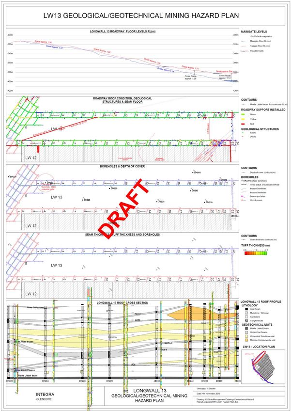
Integra Underground Mine                                                            Integra Underground Mine Longwalls 13 and 14 Coal
 Management Plan                                                                                               Resource Recovery Plan

                                                           Table of Contents
 1        Purpose ............................................................................................................................. 3

 2        Scope ................................................................................................................................. 3

 3        Planning ............................................................................................................................ 5
              3.1      Resource Description .........................................................................................................................5
                    3.1.1    Site Conditions .......................................................................................................................... 5
                    3.1.2    Overburden Stratigraphy ........................................................................................................... 5
                    3.1.3    Lithological and Geotechnical Characteristics (Roof and Floor Strata) ................................... 7
                       3.1.3.1      Roof Lithology.................................................................................................................... 7
                       3.1.3.2      Floor Lithology ................................................................................................................... 7
              3.2      Existence and Characteristics of Geological Structure ......................................................................7
                    3.2.1    Seam Dip ................................................................................................................................... 7
                    3.2.2    Cleat/jointing ............................................................................................................................. 7
                    3.2.3    Faulting ...................................................................................................................................... 8
                    3.2.4    Igneous Intrusions ..................................................................................................................... 8
                    3.2.5    Seam Splitting ........................................................................................................................... 9
                    3.2.6    Stability of Underground Workings ........................................................................................... 9
                    3.2.7    Mining Geometry ....................................................................................................................... 9
                    3.2.8    Depth of Cover .......................................................................................................................... 9
                    3.2.9    Mining Method ......................................................................................................................... 10
                    3.2.10   Schedule ................................................................................................................................. 10
                    3.2.11   Future Mining .......................................................................................................................... 10
                    3.2.12   Resource Recovery................................................................................................................. 10
                    3.2.13   Justification.............................................................................................................................. 11

 4        Implementation ............................................................................................................... 11

 5        Measurement and Evaluation ........................................................................................ 11

 6        Review and Improvement .............................................................................................. 11

 7        Document Information ................................................................................................... 12
              7.1      Related Documents..........................................................................................................................12
              7.2      Change Information..........................................................................................................................12

 Appendix A - Hazard Map ....................................................................................................... 13

 Appendices (Volume 1)

 Appendix A            Hazard Map

Number:      INTUG-793190785-159                                            Status:       Approved                 Effective: 11/08/2017
                                                                                                                                                              Page 2 of 13
Owner:       E & C Manager                                                  Version:      1.0                      Review:    11/08/2020
                                                              Uncontrolled unless viewed on intranet
Integra Underground Mine Integra Underground Mine Longwalls 13 and 14 Coal
Management Plan Resource Recovery Plan
1 Purpose
This Coal Resource Recovery Plan (CRRP) has been prepared as part of the Extraction Plan for
Longwalls 13 and 14 (LW 13 and 14).
The purpose of this CRRP is to demonstrate the effective recovery of the available resource in the
secondary extraction of LW 13 and 14 within the Middle Liddell seam at Integra Underground Mine
(IUG) using conventional longwall mining techniques.
This CRRP has been prepared in accordance with Schedule 3, Condition 20 of MP 08_0101 (MOD 6),
as a component of the IUG Extraction Plan for LW13 and 14.
2 Scope
This report provides a description of the:
Coal resources available within the Middle Liddell seam;
Proposed mining method, schedule and mine plan;
Resource recovery and effects on future mining;
Outline proposed geological and geotechnical hazards (Appendix A); and
Justification for the mine plan.
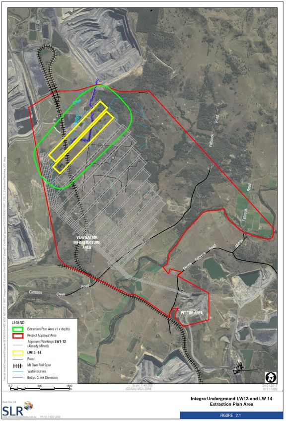
Graphical Plans (included as Volume 3 of the Extraction Plan) provide details of the coal resources,
existing and proposed workings, predicted impacts to surface features and additional supporting
information. The plans have been prepared in accordance with the Guidelines for the Preparation of
Extraction Plans - Draft V5 (Department of Planning and Environment (DP&E) and the NSW Division
of Resources and Energy, 2015). The Extraction Plan area is shown in Figure 2-1.
Number: INTUG-793190785-159 Status: Approved Effective: 11/08/2017
Page 3 of 13
Owner: E & C Manager Version: 1.0 Review: 11/08/2020
Uncontrolled unless viewed on intranetIntegra Underground Mine Integra Underground Mine Longwalls 13 and 14 Coal
Management Plan Resource Recovery Plan
Figure 2-1 – Extraction Plan Area
Number: INTUG-793190785-159 Status: Approved Effective: 11/08/2017
Page 4 of 13
Owner: E & C Manager Version: 1.0 Review: 11/08/2020
Uncontrolled unless viewed on intranetIntegra Underground Mine Integra Underground Mine Longwalls 13 and 14 Coal
Management Plan Resource Recovery Plan
3 Planning
3.1 Resource Description
3.1.1 Site Conditions
The mine access, entries and primary surface facilities are located approximately 12 km northwest of
Singleton. LW 13 and 14 is within the Middle Liddell Seam. Roadway development will be by
continuous miners and secondary extraction will be by retreating longwall methods.
3.1.2 Overburden Stratigraphy
The coal seams of economic interest on Coal Lease (CL382) are in the Foybrook Formation of the
Wittingham Coal Measures. The stratigraphic sequence at Glennies Creek is illustrated in Figure 3-1.
The Foybrook Formation comprises a sequence of coal seams, mudstone, siltstone, sandstone and
conglomerate, which formed as a river dominated delta system, which prograded from the New
England Fold Belt. The Foybrook Fm is 300 -350m thick at the IUG.
The lower seams (Hebden, Barrett, Lower Liddell and Middle Liddell) are thought to have developed in
a lower delta plain environment. In the case of the higher seams (Upper Liddell, Arties and Pikes
Gully) the lateral migration of the main coal forming environment correlates with an observed lateral
facies change from lower to upper delta plain conditions.
The Foybrook Formation is overlain by the Bulga Formation, a relatively thin (15m) bioturbated
laminite, and the marine Archerfield Sandstone.
The Burnamwood Formation represents a return to a coal measure sequence with the deposition of
the Bayswater Seam, a dull, high ash, durain-rich coal, easily identified throughout most of the Hunter
Coalfield, but which is not easy to correlate with certainty on the eastern limb of the Rix's Creek
syncline. The seam thins rapidly to the south and east of the Ravensworth East (Swamp Creek) open
cut.
Number: INTUG-793190785-159 Status: Approved Effective: 11/08/2017
Page 5 of 13
Owner: E & C Manager Version: 1.0 Review: 11/08/2020
Uncontrolled unless viewed on intranetIntegra Underground Mine Integra Underground Mine Longwalls 13 and 14 Coal
Management Plan Resource Recovery Plan
Figure 3-1 – Typical Stratigraphic Column
Burnamwood FM
Jerrys Plains
Subgroup
Mudstone
Siltstone
Sandstone
Bayswater
Bulga
FM Coal
Pebbly Sandstone
Wittingham Coal Measures
Lemington Conglomerate
Sandstone and
Singleton Supergoup
Mudstone Interbedded
Coal and Bands
Foybrook Formation
Vane Subgroup
Pikes Gully
Arties
Upper Liddell
Middle Liddell
Lower Liddell
Barrett
Hebden
Saltwater
Creek FM
Siltstone
Mulbring
Maitland
Group
Figure 1
TYPICAL STRATIGRAPHIC COLUMN
Number: INTUG-793190785-159 Status: Approved Effective: 11/08/2017
Page 6 of 13
Owner: E & C Manager Version: 1.0 Review: 11/08/2020
Uncontrolled unless viewed on intranetIntegra Underground Mine Integra Underground Mine Longwalls 13 and 14 Coal
Management Plan Resource Recovery Plan
3.1.3 Lithological and Geotechnical Characteristics (Roof
and Floor Strata)
3.1.3.1 Roof Lithology
The immediate roof of the Middle Liddell seam is usually a competent poorly bedded mudstone or
siltstone, 0.5m – 2.0m thick and overlain by laminite or bedded sandstone. In places the mudstone is
laminated (shaly) and weaker. Locally it may be absent altogether with coarser sandstones cutting
down to seam roof level.
The lithologies forming the mine roof range from strong thick bedded to massive coarse grained
sandstone units (festooned channels) through to weak shale beds. Changes can occur over only a few
metres.
Notwithstanding the above observation, strata within the mining area is moderate to high strength and
(in the absence of high horizontal stress) require a generally low level of primary support.
3.1.3.2 Floor Lithology
In the south of CL382 the floor of the Middle Liddell seam comprises a fine sandstone or siltstone,
usually with a thin soft mudstone immediately below the seam. To the north softer mudstone with
interbanded coal and rare sandstone interbeds is predominant.
As the mine proceeds down dip, the floor has become softer as coal laminations and bands become
more abundant in the immediate floor of the Middle Liddell seam.
3.2 Existence and Characteristics of Geological
Structure
Appendix A of this document outlines a Hazards Map for LW 13. The Hazards Map will assist in
determining mitigation measures in the mining design to reduce subsidence whilst maximising
resource recovery.
3.2.1 Seam Dip
The main structural feature of CL382 is the northward plunging Rix's Creek Syncline. It is flanked by
the Camberwell Anticline to the west and the Darlington Anticline to the east. These structures are
asymmetric, the anticlines with steep eastern limbs and more gently dipping western limbs. The
syncline plunges to the north at 2-3 degrees. Dips on the eastern limb vary between 5-10 degrees and
on the western limb between 10-25 degrees. In the west of CL382, the lowest parts of the syncline
dips are 2-4 degrees. Northwest of CL382, the axis of the Rix's Creek Syncline changes direction to
trend sub-parallel to the Hebden Thrust, eventually being terminated by the thrust in the Swamp Creek
lease.
Panels LW 13 and 14 are expected to retreat up dip of approximately 2 -3 degrees.
3.2.2 Cleat/jointing
Mapping of the Camberwell North Pit highwall in 1994 showed strong WNW (280 o-285oG) and NE
(45oG) joint trends in non-coal strata. Joints in outcropping rocks in the Ravensworth district were
mapped by Gray (1975). The principal joint directions recorded are NNE and NE in the southeast, and
NW and NE in the northwest. These directions are broadly similar to the regional fault trends.
Jointing in the roof strata in the underground workings is rarely observed, but where present is usually
sub-parallel to cleat direction.
The Middle Liddell seam in the underground workings is well-cleated. Measured coal cleat directions
coincide with the strong WNW joint trend measured in the highwall. There is a small offset between
directions measured in the Main West Headings steeply dipping strata on eastern limb of Rix’s Creek
Number: INTUG-793190785-159 Status: Approved Effective: 11/08/2017
Page 7 of 13
Owner: E & C Manager Version: 1.0 Review: 11/08/2020
Uncontrolled unless viewed on intranetIntegra Underground Mine Integra Underground Mine Longwalls 13 and 14 Coal
Management Plan Resource Recovery Plan
Syncline) and the North West Mains (representing production districts in the shallow dipping seam in
the base of the syncline). This suggests a change in structural domain which may also be reflected in
the absence of faults in the production districts, and a change from brittle to more plastic styles of
deformation.
3.2.3 Faulting
To the northwest extensive underground and open cut workings in the Bayswater Seam and
underlying Foybrook Formation coals around Ravensworth have encountered NE (25-40 o magnetic,
35-50 o grid) trending zones of normal faults with individual throws up to 10m, but no significant
displacement across the whole zone. Individual faults within the zones define horst and graben
structures, are hinged, offset and overlapping, and are commonly at a low angle (10-15o) to the
regional strike of the zone (CSIRO, 1992 pp3-54 to 3-63).
The Hebden Thrust (a splay of the Hunter Thrust at Liddell where it has a displacement of 220m. and
a dip of 20-25 degrees) was previously projected into CL382 to re-join the Hunter Thrust close to
where the Hunter Thrust crosses Glennies Creek. However, two seismic lines recorded in 1989-90
(Lines J & K) extended over the inferred position of the Hebden Thrust and failed to locate any
significant structure. Drilling and dipmeter logging at Mount Owen during 1992-93 suggests that the
difference in elevation between the Foybrook Formation coals intersected in the Mount Owen prospect
and CL382 can be accounted for by a faulted monoclinal structure rather than large scale faulting. The
high side of this structure has been informally termed the "Hebden Block".
Work at Mount Owen has also provided evidence of a zone of steeply dipping coal measures strata,
approximately 1km wide, immediately to the west of the Hunter Thrust. It seems likely that the zone is
bounded by another splay thrust (the "Ellis Fault"), which may extend to the south of Glennies Creek in
the Thomas Lane area. The evidence for this structure includes near vertical strata at surface in A429,
just to the north of CL382, dips of 50-60 degrees to the NE in R2002 on the northern border of CL382,
and dips of 75 degrees in DH025. The "Ellis Fault" may have been intersected at 40-45m in R2003.
A 0.1m-0.9m normal fault trending NE (approx. 25o) is expected in LW 13 and 14. It was mapped in
the North Mains headings (0.3m) and again in the tailgate (0.1m) and maingate (0.9m) of LW 13. An
approximate 0.5m fault has also been mapped in the North Mains and maingate 14 that will be
intersected in the outbye end of LW 14.
3.2.4 Igneous Intrusions
Regionally dykes are sub-parallel with northeast-trending faulting or are oriented meridionally or in the
25-35o G direction. An exception is the WNW feature detected in the 1998 ground magnetometer
survey.
A thin (0.5m) NE (30 o G) trending dyke was intersected in Maingate 3, but its southern termination is
within LW 3 and it was not observed in the NW Mains. This dyke has also been intersected in MG4,
where it is 0.8-0.9m thick in the roof and belling out in the seam, and in MG5 and the LW 6 installation
roadway, where it is up to 1.5m thick.
A dyke system associated with a fault was encountered in the Camberwell open cut and shown by a
ground magnetic survey to continue into CL382.
Generally two vertical dykes one to two metres thick are present either side of a zone of intense
shearing and deformation. In the northern highwall in November 1992 the western dyke showed vent
or plug like characteristics, thickening to 11m and containing conglomerate boulders in a soft matrix.
The total width of the zone is 20m-25m. Further south the dykes thin and displacements of up to 2m
were recorded. This system does not affect the underground resource.
Minor intrusives were intersected in the Hebden Seam in JB032, located in the north-west corner of
CL382. The intersection appears to have been made in close proximity to a dyke, since the extent of
cindering and induration is far greater than would be expected from the intrusives actually intersected.
Also in this area, a dyke trending NE is well known from the Ravensworth East and Mount Owen
mines, but does not pass through CL382.
Other minor intrusives were reported from DH208 and in several Camberwell drillholes.
A 0.3m thick dyke has been mapped in tailgate 13. The projection of this dyke was not mapped in the
install road approx. 175m away. It is expected to terminate shortly into the panel. No further intrusions
are expected in LW 13 and 14.
Number: INTUG-793190785-159 Status: Approved Effective: 11/08/2017
Page 8 of 13
Owner: E & C Manager Version: 1.0 Review: 11/08/2020
Uncontrolled unless viewed on intranetIntegra Underground Mine Integra Underground Mine Longwalls 13 and 14 Coal
Management Plan Resource Recovery Plan
3.2.5 Seam Splitting
A floor section of the Middle Liddell seam comprising of interlaminated coal and mudstone that is not
present in the south of CL382, but is now being recorded from inbye areas of the mine. It is separated
from the main seam by a mudstone band that thins to less than 0.20m in the NW of the lease, where
this ply can be included in the working section with some loss of percentage yield.
Discontinuous stone bands in the upper section of the Middle Liddell seam impact on the mining
operation. These occur both above (the A band) and below (the B band) the claystone penny band
that typically occurs about 0.5m below the seam roof. These bands are lenticular and may be up to
1.8m thick. Generally they do not replace coal but increase seam thickness, although the A band may
thicken to the extent that it replaces the top 0.5m or so of the seam and effectively merges with the
roof. Weak roof conditions are often associated with the A band, as coal layers above the band persist
into the mining roof.
The interpretation of the depositional environment of the coal seam is that as mining advances to the
north, away from the active, high energy zone adjacent to the main distributary channel and further
into the backswamp, the proportion of non-coal material in the seam will decrease.
3.2.6 Stability of Underground Workings
The proposed pillars in the application area are designed to provide stable underground workings for
the period of development and subsequent extraction. As such, pillars are designed with an
appropriate factor of safety and width-to-height ratio for their purpose. Further details of pillar stability
are outlined within the High Risk Notification.
Detail on predicted subsidence impacts, the associated method of prediction and relevant subsidence
parameters can be found in the Extraction Plan main report.
Accompanying the designed mining layout is a monitoring program with the objective to monitor
roadways, pillars and panel performance, and to ensure the adequacy of the design. Monitoring is
conducted during both development and secondary extraction.
3.2.7 Mining Geometry
The layouts LW 13 and 14 within the Middle Liddell seam are shown in Figure 2-1. A summary of the
proposed dimensions of these panels is provided in Table 3-1. It is proposed that the longwalls would
be extracted in order of LW13 first and LW 14 second.
Table 3-1 Geometry of the Proposed Panels LW 13 to LW 14
MG Chain
Nominal Average Panel
Pillar Width LW Void LW Void
Panel Gate Road Extraction Extraction
Coal Rib to Width (m) Length
Width (m) Height (m) Tonnes (Mt)
Rib (m)
LW 13 5.2 50.5 256.5 2090.2 2.9 2.4
LW 14 5.2 49 256.5 2024.2 2.7 1.8
3.2.8 Depth of Cover
The cover depth over LW 13 and 14 block ranges from between 400m and 500m, with the start of the
panels being the deepest. These depth changes are related to both the seam dip and changes in
surface topography.
Number: INTUG-793190785-159 Status: Approved Effective: 11/08/2017
Page 9 of 13
Owner: E & C Manager Version: 1.0 Review: 11/08/2020
Uncontrolled unless viewed on intranetIntegra Underground Mine Integra Underground Mine Longwalls 13 and 14 Coal
Management Plan Resource Recovery Plan
3.2.9 Mining Method
The proposed mining method represents a continuation of the current system employed at the IUG,
namely continuous miner development supporting longwall extraction.
Roadway development in gate roads and main headings will be carried out using continuous miners.
These continuous miners with integrated roof and rib bolting rigs. Shuttle cars are employed to
transport the coal from the continuous miners to the conveyor system.
Secondary extraction will be by retreating longwall methods. The longwall equipment is capable of
operating in the height range of 2.1m-3.2m and of negotiating the expected geological conditions,
including any sandstone channels. With an average seam thickness of 2.8m, the full seam will be
extracted.
Longwall extraction is the preferred method of mining as it provides the greatest production and
economic efficiencies when compared to other options. It is the only method that can provide
acceptable economic returns for extraction of the area based on coal quality, required production
levels, current economics and forecasted economic parameters.
3.2.10 Schedule
Table 3-2Error! Reference source not found. outlines the scheduled start date, completion date and
duration of the mining of LW 13 and 14.
Table 3-2 - Timing of longwall mining for LW 13 to 14
Panel Start Date Completion Date Estimated Duration (days)
LW 13 1 May 2017 19 January 2018 263
LW 14 16 February 2018 20 September 2018 216
3.2.11 Future Mining
A future decision on whether mining would occur beyond LW 14 will be determined prior to 30 June
2017. A new Extraction Plan would be prepared if additional mining is to occur in the future.
3.2.12 Resource Recovery
The method of extraction selected allows for maximum resource recovery whilst providing safety for
the workforce. There are no significant environmental impacts that preclude longwall extraction of LW
13 and 14.
In the initial planning of the area an option study was conducted whereby a number of alternative mine
plans were considered having regard to the lease boundaries, exploration geological data and initial
environmental assessment details. The plan and layout have been continually reassessed as
additional exploration, geological, and environmental data become available.
Number: INTUG-793190785-159 Status: Approved Effective: 11/08/2017
Page 10 of 13
Owner: E & C Manager Version: 1.0 Review: 11/08/2020
Uncontrolled unless viewed on intranetIntegra Underground Mine Integra Underground Mine Longwalls 13 and 14 Coal
Management Plan Resource Recovery Plan
The estimated recovery of the resource for LW 13 and 14 is provided in Table 3-3.
Table 3-3 - Estimated Resource Recovery
Total Tonnes of Coal (within extraction area) 6.56.5
Total Tonnes Extracted through Development 0.2
Tonnes Extracted by Longwall 4.2
Percentage Recovery 68%
3.2.13 Justification
The layout, as indicated on Figure 2-1, has been developed based on extensive drilling,
environmental investigation and assessment and consultation with relevant authorities.
The layout and method also provide an extraction layout which maximises the efficient use and
management of resources through maximising resource utilisation within an area of historical
underground workings and using well established surface facilities. There are no significant
environmental impacts that preclude longwall mining within the Extraction Plan Area.
The subsidence monitoring program contained within the Extraction Plan summarises the overall
monitoring of mining impacts on the natural and built environments, with management actions detailed
in the relevant environmental management plan(s).
4 Implementation
The implementation of mitigation measures for subsidence impacts is outlined within the Built
Features Management Plan, specific asset management plans and environmental management plans.
Appendix A outlines a Hazards Map for LW 13. This map will be finalised in panel review prior to
extraction. LW14 Hazard Map will be generated during development of LW14 and finalised in a pre
mining panel review.
5 Measurement and Evaluation
Monitoring and inspections associated with the mining of LW 13 and 14 will be completed in
accordance with the Subsidence Monitoring Program and specific management plans.
6 Review and Improvement
Review of the Extraction Plan and/or any of the sub-plans, and revision if necessary, shall occur
where significant unpredicted impacts and/or environmental consequences are identified through the
monitoring and management strategies proposed in the Extraction Plan.
Review of the Extraction Plan and/or any of the sub-plans is also required following any modification to
PA 08_0101 (MOD 6), or if directed by the Secretary of the DP&E.
Any revision to the Extraction Plan including component sub-plans must be completed to the
satisfaction of the Secretary of the DP&E.
Number: INTUG-793190785-159 Status: Approved Effective: 11/08/2017
Page 11 of 13
Owner: E & C Manager Version: 1.0 Review: 11/08/2020
Uncontrolled unless viewed on intranetIntegra Underground Mine Integra Underground Mine Longwalls 13 and 14 Coal
Management Plan Resource Recovery Plan
7 Document Information
7.1 Related Documents
This CRRP forms part of the overall Extraction Plan documentation, with this including a main
document and other management plans.
7.2 Change Information
Full details of the document history are recorded in the document control register, by version. A
summary of the current change is provided in Table 7- below.
Table 7-1– Change information
Version Date Change Summary
1.0 January 2017 New document
Number: INTUG-793190785-159 Status: Approved Effective: 11/08/2017
Page 12 of 13
Owner: E & C Manager Version: 1.0 Review: 11/08/2020
Uncontrolled unless viewed on intranetIntegra Underground Mine Integra Underground Mine Longwalls 13 and 14 Coal
Management Plan Resource Recovery Plan
Appendix A - Hazard Map
Number: INTUG-793190785-159 Status: Approved Effective: 11/08/2017
Page 13 of 13
Owner: E & C Manager Version: 1.0 Review: 11/08/2020
Uncontrolled unless viewed on intranetYou can also read