KE CHAI XBT: FPGA Accelerated Binary Translation - OhioLINK ETD ...
←
→
Page content transcription
If your browser does not render page correctly, please read the page content below
XBT: FPGA Accelerated Binary Translation

                              KE CHAI

  Submitted in Partial Fulfillment of the Requirements for the Degree of

                         Master of Science

             Thesis Advisor: Dr. Christos A. Papachristou

    Department of Electrical, Computer and Systems Engineering

           CASE WESTERN RESERVE UNIVERSITY

                              August, 2021
XBT: FPGA Accelerated Binary Translation
Case Western Reserve University
Case School of Graduate Studies
We hereby approve the thesis1 of
Ke Chai
for the degree of
Master of Science
Christos A. Papachristou
Committee Chair, Advisor 07/16/2021
Department of Electrical, Computer and Systems Engineering
Daniel G. Saab
Committee Member 07/16/2021
Department of Electrical, Computer and Systems Engineering
Seyed Hossein Miri Lavasani
Committee Member 07/16/2021
Department of Electrical, Computer and Systems Engineering
1
We certify that written approval has been obtained for any proprietary material contained therein.Table of Contents
List of Tables v
List of Figures vi
Acknowledgements vii
ABSTRACT 1
Chapter 1. Introduction 2
Background 2
Motivation 2
Contribution 3
Outline 3
Chapter 2. Literature Review 5
Binary Translation 5
Dynamic Binary Translation 5
Hardware-Accelerated Binary Translation 6
Chapter 3. Methodology 7
Configuration blocks 7
Translation Blocks 8
Reallocation Registers 9
Branch Offset Issues 10
Unrecognized Instructions 11
Chapter 4. Prototype Design 12
Instruction Set 12
System Design 12
Microcode 14
Translation Process 15
Architecture Implementation 17
Chapter 5. Results 21
iiiDesign Reports 21
Benchmark Technique 22
Measurement of Speedup 22
Results 23
Chapter 6. Conclusions 25
Chapter 7. Future Work 26
References 27
ivList of Tables
4.1 MIPS32 User App. Instructions 13
4.2 Description of XBT Blocks 14
4.3 IMB/AMB Microcode 15
4.4 Register Reallocation Example 16
4.5 Unfolding I-type Example 16
4.6 Unfolding Load/Store Example 17
4.7 Reordering Example 17
4.8 Complex Instruction Example 18
4.9 XBT Configuration Registers 20
5.1 Translation Time: BT vs XBT 24
vList of Figures
3.1 XBT System Block Diagram 8
3.2 Address Mapping Flow 11
4.1 An XBT Configuration Instance 13
4.2 Zynq 7000 SoC 24 18
4.3 Block Design of XBT in Vivado 19
5.1 Power Report 21
5.2 Utilization Report 22
5.3 Timing Report 22
viAcknowledgements
First I want to thank my advisor Dr. Papachristou and Dr. Wolff. They have
generously provided me with their knowledge, experience and help. Without them,
this thesis would never be finished.
Also I want to thank the committee members who have paid effort into reading
this thesis.
Thanks to my parents who gave me their consistent support, both emotionally
and economically, to pursue my degree.
Last but not least, I want to thank my wife who abandoned her well-paying job
and followed me to America to take care of me. I really enjoyed her company and
will never forget how much she has sacrificed for me.
viiABSTRACT
XBT: FPGA Accelerated Binary Translation
Ke Chai
Binary translation (BT) is the process of converting executable binary from one
instruction set architecture (ISA) to another. Accelerated binary translation (XBT)
refers to BT using FPGA for hardware acceleration and feeding the target proces-
sor at-speed. This work proposes a reconfigurable pipelined structure built on
FPGA that performs XBT on different ISAs. An XBT system that translates MIPS to
RISC-V is implemented and tested on the Xilinx Zynq platform. Results of several
benchmarks show obvious speedup of approximately 48 times compared to an
equivalent software approach.
11 Introduction
1.1 Background
Binary translation (BT) is the process of converting executable binary from one
instruction set architecture (ISA) to another 19 . BT makes it possible to migrate
applications between two ISAs without the need of source code and recompila-
tion 8,9,26 . For example, a legacy MIPS program can be translated to an equivalent
RISC-V program using BT and run on a RISC-V processor. BT also serves as an
emulation method which has higher performance than normal software-based
interpretation. Emulators like QEMU use BT techniques for better performance 5 .
BT is a way to achieve Architecture-Independent Computing (AIC) which means
to enable executing code of different ISAs on any machine 3 .
There are mainly two kinds of BT approach: static binary translation (SBT) and
dynamic binary translation (DBT). SBT translates the whole binary code before
the execution, while DBT translates at runtime. Software DBT is more widely used
for emulation purpose since it deals better with problems such as self-modifying
code, but it usually has worse performance than SBT.
1.2 Motivation
Unlike a program originally built for the target ISA, a binary translated program
from another ISA suffers from the performance loss due to the differences between
the ISAs 25 . Since DBT systems translates codes on-the-fly, the translation overhead
2Introduction 3 is also a key factor that affects performance 6,19 . Accelerating the translation pro- cess is an important part of the overall speed improvement in the DBT process. FPGAs are widely used in applications which need flexible hardware accelera- tion such as AI and neural networks. FPGA fabrics are even embedded into system- on-chips (SoCs) and have high-speed, high-bandwidth connection to processors. Pipelining on FPGA allows the ability to have overlapping parallelism in prob- lems dealing with large amount of sequential data. Though being less efficient compared to ASICs 17 , FPGAs have more flexibility that ASICs cannot provide. The FPGA’s reprogrammability enables the system to switch between different config- urations at runtime. 1.3 Contribution This work proposes a pipelined structure built on FPGA that performs accelerated binary translation (XBT). Using FPGA could make better use of parallelism, which enhances the performance. With the speedup brough by the FPGA fabrics, the method could efficiently generate semantically equivalent target code (i. e. the gen- erated binary after translation) from source code (i. e. the binary to be translated). In addition to the increase of translation speed, it also provides more flexibility at runtime. An XBT prototype that translates MIPS to RISC-V is presented in this work. Several benchmarks are run on a Xilinx Zynq chip using both XBT approach and software-based BT approach. Comparation of their translation speed proves that XBT have greater performance gain on the BT process. 1.4 Outline Section 2 cites and comments on some related work and background study of relevant BT topics.
Introduction                                                                   4

   Section 3 describes the methodology of XBT and how XBT solves the key prob-
lems that occurs in BT process.
   Section 4 gives a specific prototype of XBT translates MIPS to RISC-V. Details
of the design are also shown.
   Section 5 gives the design report, benchmark method and result of the MIPS to
RISC-V XBT on Xilinx Zynq platform.
   Section 6 gives the conclusion from the results.
   Section 7 discusses about the shortcomings and future work to be done.
2 Literature Review

2.1 Binary Translation

Sites et al. 22 described the concept of BT in a 1993 paper, in which two binary trans-
lators targeting Alpha AXP computers are also given. Altman et al. 2 introduced BT
as an effective way of automatic code porting without recompilation. Cifuentes et
al. 11 developed a reusable, component-based BT framework called UQBT, which
can adapt easily and inexpensively to different source and target machines. More
works 4,13,18,23 are proposed on the optimization of BT process.
   In order to migrate legacy x86 applications to the newly-designed M1 processor
with ARM architecture, Apple developed a BT system named Rosetta 2 16 . It uses
static BT approach that translates before the execution. However, It is not capable
for translating kernel extensions or Virtual Machine apps.

2.2 Dynamic Binary Translation

The concept of DBT can date back to a 1996 paper by Cifuentes et al. 10 . This pa-
per argues that dynamic binary translators can reach performance equal to static
ones while requiring less complex environment at runtime. It also presents a new
technique as a complement to a retargetable binary translator.
   Probst 19 gave the definition and usage of DBT in his 2002 paper. It shows so-
lutions to the problems that occurs in the DBT process like jump/branch offset

                                          5
Literature Review 6 issues, register mapping and conditional bits. It also mentions the existence of a translation cache. There are also works using DBT for architectural emulation. Chapman et al. 7 combines DBT and virtualization for cross-platform emulation. The prototype, named “MagiXen”, is an implementation of a Xen virtual machine monitor that can run IA-32 virtual machines on Itanium platforms. DBT targeting VLIW machines is also designed for static scheduling, which can handle the trade-offs between performance and hardware complexity. Ebcioglu et al. 1,12 Proposed an architecture called DAISY, i. e. Dynamically Architected Instruc- tion Set from Yorktown, to use DBT and VILW machines to gain high instruction level parallelism with simpler hardware designs. 2.3 Hardware-Accelerated Binary Translation There are existing works that involve hardware acceleration in DBT process. Yao et al. 25 propose an FPGA based hardware-software co-designed DBT system from x86 to MIPS. A “CCflag” register and several user defined instructions are added to the MIPS processor core to resolve the problem brought by x86 conditional flags and different byte order, i. e. endianess. To enhance the speed of translation, a jump address look-up table (JLUT) is also implemented as a part of the translator. Though involving FPGA, this work does not develop its reconfigurability. Rokicki et al. 20 proposed a hardware-accelerated DBT operates on MIPS bina- ries and targets a custom VLIW core. A small single-issue processor is dedicated to the DBT process, along with blocks designed with high-level synthesis (HLS) tech- nology. A more recent paper of Rokicki 21 even started to develop this approach on heterogeneous multi-core architectures to lower the power consumption while maintaining considerable performance.
3 Methodology

   The XBT system is implemented on the FPGA fabric as shown in Figure 3.1.
The green blocks are the configuration blocks that take charge of managing and
monitoring the current FPGA configuration. The blue blocks are the translation
blocks, which are the main components where XBT is performed. The blocks in
XBT can be accessed by the processor at-speed through AXI interfaces.
   In the following sections, we will discuss the functionality of each blocks and
how they resolve problems in BT process.

3.1 Configuration blocks

The profile monitor and configuration manager in Figure 3.1 are implemented for
flexible reconfiguration. The profile monitor collects and analyzes statistics of the
currently translating program, and the configuration manager switches between
different configurations according to the program context. The FPGA uses alter-
native configurations for common instruction flows. For example, applications
that have a lot of string processing will load the FPGA string flow configuration.
If the user application uses a lot of integer math, then the FPGA will load the in-
teger math configuration which is optimized for integer flow. Using specifically
optimized configurations for different kinds of instruction flows can lower the la-
tency of translation, which is essential for at-speed execution. Since the resources
on the FPGA are limited, it is not realistic to put all the configurations on the FPGA.
Further more, the delay of the circuits gets worse as the FPGA blocks grows bigger.

                                          7
Methodology 8
Figure 3.1. XBT System Block Diagram
The configuration blocks can also manage the FPGA configurations and provide
choices on different tradeoffs.
3.2 Translation Blocks
The translation work is mainly performed by the instruction mapping block (IMB)
in Figure 3.1, which is divided into several pipeline stages. The pipeline stages may
vary depending on the source and target ISAs. The source code to be translated is
stored in the source buffer, and the target code will be written into the target bufferMethodology 9 after the translation process. The address mapping block (AMB) and the address mapping table (AMT) work together to derive and store the address mappings be- tween the source program counter (SPC) addresses and the target program counter (TPC) addresses. As the number of instructions usually changes during translation, the targets of branch instructions need to be adjusted. Deriving and Storing the mapping information in the AMB can speedup the branch offsets look-up during translation. The translation cache is designed for lower latency. During at-speed execution, the processor fetches repeated instructions in contexts such as loops. Repeated translation information of the instructions can be kept so that they do not need to be translated more than once. If a source instruction is in the translation cache, the translated target instruction can be read directly from the cache without going through the translation process repeatedly. The translated instructions read from the translation cache can be directly executed at-speed on the target processor. 3.3 Reallocation Registers Due to the architectural difference between the two ISAs, one source instruction could be translated into two or more target instructions. As a result, registers are needed to pass on intermediate results between these instructions. If these regis- ters are previously occupied, their original value should be well preserved. These stored register values should be restored when they are further needed by other instructions. A small memory region called scratch pad memory (SPM) is allocated in order to solve the register reallocation problem. The original values of the regis- ters can be written into specific locations in the SPM, and loaded back afterwards. SPM can be a memory region allocated on the FPGA or in the main memory, which is configured through the configuration blocks. The register reallocation is performed during the translation process by a re- allocation module in the IMB. It tracks the usage of each register and the register values in the SPM. When reallocation is needed, it inserts load/store instructions
Methodology                                                                           10

and changes the source and destination registers in the instructions. It can be con-
figured to assign registers that are available for reallocation.
   In most of the RISC architectures like RISC-V and MIPS, the memory is accessed
by load/store instructions, which form effective addressing by adding up an imme-
diate offset and a register value 15 . Therefore, another special register called scratch
base register (SBR) is needed in order to access the SPM. The SBR stores the base
address of the SPM so that the SPM can be accessed by load/store instructions
using SBR and another offset value. The scratch base register cannot serve as a
reallocation register.
   Since the SPM is needed during runtime, it should be initialized by software be-
fore the execution of the program. The memory region for SPM should be properly
allocated, and its base address should be stored in the scratch base register.

3.4 Branch Offset Issues

As one source instruction could be translated into several target instructions, the
address offsets in the target branch instructions are different from the ones in the
source instructions 25 . To solve this issue, the AMB is designed to derive how many
target instructions will be generated out of one source instruction and calculate
the relevant TPC address of every SPC address. The TPC addresses are stored into
AMT afterwards.
   As shown in Figure 3.2, the AMT can be implemented as a block memory with a
write port and a read port connecting to the AMB and the IMB respectively. The SPC
values are truncated and used as memory address to access the AMT. Accordingly,
the TPC values are the data stored in this memory. At runtime, the TPC of the
branch target is needed in IMB when it recognizes a branch instruction. The SPC
will be sent to AMT and it will return its corresponding TPC. After that, the new
branch offset is calculated based on the branch target TPC and the TPC of the
branch instruction itself.
Methodology                                                                        11

                               Figure 3.2. Address Mapping Flow

   The AMB works simultaneously with the IMB, and is expected to run faster than
the IMB. If the IMB is querying data that AMB and AMT has not yet done with, the
IMB will stall its pipeline and wait until the data are ready.

3.5 Unrecognized Instructions

In actual practice, there are some instructions that cannot be simply translated or
not even recognized. This could include reserved instructions, privileged instruc-
tions and some instructions with complicated operations, depending on different
source/target ISAs. In this case, they will be translated to a system call instruc-
tion or a software interrupt. Parameters including the original instruction binaries
are passed on in specific registers so that software, or say handler, could decide
whether this instruction is valid and perform a software translation on-the-fly.
4 Prototype Design
A prototype of XBT from MIPS to RISC-V has been designed and implemented.
Both belonging to the RISC family, MIPS and RISC-V are similar to each other in
the instruction set composition, while having differences in encoding formats and
data representation. Using them as an example for source and target of XBT can
illustrate how key problems of BT are solved on FPGA and lower the complexity of
the design.
4.1 Instruction Set
For user applications, we need only to implement an XBT of the user application
instruction set. It is not necessary to implement the operating system or privileged
supervisor instructions. The user instructions of the MIPS32 release 1 ISA 14 are
selected as a source to be translated, as shown in Table 4.1. It mainly contains the
arithmetic/logic instructions, the memory access instructions, the unconditional
jump instructions and the conditional branch instructions. These instructions are
translated to the base instruction set of the RISC-V, i. e. “RV32I”.
4.2 System Design
The detailed design is shown in Fig. 4.1. The IMB and AMB are implemented in a
pipelined fashion. Some blocks with the same name in IMB and AMB are different
12Prototype Design 13
Table 4.1. MIPS32 User App. Instructions
Category Instructions
I-type A/L ADDI ADDIU SLTI SLTIU ANDI ORI XORI LUI
R-type A/L SLL SRL SRA SLLV SRLV SRAV ADD ADDU SUB
SUBU AND OR XOR NOR SLT SLTU
Load/Store LB LBU LH LHU LW SB SH SW
Jump J JAL JR JALR
Branch BEQ BNE BLTZ BGEZ BLEZ BGTZ
hardware instances of the same design, for example, “Fetch” and “Decode”. The
detailed function of each pipeline stage is listed in Table 4.2.
Figure 4.1. An XBT Configuration InstancePrototype Design 14
Table 4.2. Description of XBT Blocks
Pipeline Stage Description
Fetch Fetch instruction from MIPS code buffer
Decode Decode MIPS instructions into microcode
Instruction Exchange every branch instruction with its delay slot
Reorder instruction
Register Insert load/store instructions to gain/recover the
Reallocation original value of the reallocated registers when needed
Unfold Extend the I-type instructions with immediate
Values value wider than 12 bits into more instructions
Address Map the branch / jump target SPC to TPC according
Mapping to the AMT
Instruction Translate MIPS microcode into one or more equivalent
Equivalency RISC-V microcode
Code Mapping Generate RISC-V instructions from microcode
Address Derives the number of RISC-V instructions a MIPS
Reorder instruction will be translated into, and writes the AMT
As shown in Figure 4.1, IMB and AMB fetch MIPS instruction simultaneously
from the source buffer. Instructions are passed onto the next stage every clock
cycle, so when one of the stages are trying to produce more than 1 instruction in
IMB, its previous stages are blocked. On the contrary, AMB does not have blocking
stages, so it fetches more instructions than IMB in the same period of time.
4.3 Microcode
Instead of passing on real MIPS instruction code, the pipeline stages use microcode
to represent MIPS or RISC-V instructions. Each MIPS instruction is interpreted into
MIPS microcode in the “Decode” stage and mapped to one or more RISC-V mi-
crocode words in the “Instruction Equivalency” stage. By transforming the instruc-
tions to microcode, the data are more clearly represented and more information
is provided. Pipeline stages could decide how a microcode should be processed
according to its “family” field and “type” field, which would simplify the circuit
and accelerate the process. Table 4.3 shows how some microcode fields are rep-
resented. For example, a MIPS “ADD $3, $1, $2” instruction will be classified intoPrototype Design 15
family “R-type” with code 0x3, and type “ADD” with code 0x6. Assuming its PC
value is 0xbfc00000, its microcode word is the combination of {0xbfc00000, 0x3,
0x6, 0x1, 0x2, 0x3, 0x0}.
Table 4.3. IMB/AMB Microcode
Variable Width (bits)
Source PC 32
Instruction Family 4
Instruction Type 4
Source Register 1 5
Source Register 2 5
Destinaltion Register 5
Extended Immediate 32
4.4 Translation Process
Some examples are shown to illustrate how MIPS instructions are translated to
RISC-V instructions. Both ISAs belong to the RISC family and show lots of simi-
larity, so in most of the cases, MIPS instructions can be one-to-one translated to
RISC-V instructions 22 . However, there are special cases that one source instruc-
tion translates to multiple target instructions. Examples of these special cases are
shown below.
4.4.1 Register Reallocation
An example is shown in Table 4.4. In this example, register 27 is used as the SPM
base register, and registers 24, 25 and 26 are reallocation registers. When their orig-
inal values are needed, they are loaded from the SPM, and written back after the
operation.
4.4.2 Unfolding Instructions with Large Offset
MIPS I-type instructions have 16 bits offset field while RISC-V only have 12. As
a result, large immediate numbers with more than 12 bits need to be stored inPrototype Design 16
Table 4.4. Register Reallocation Example
MIPS Code MIPS Assembly RISC-V Code RISC-V Assembly
0x033ac020 ADD $24, $25, $26 0x008dac83 LW x25, 8(x27)
0x00cdad03 LW x26, 12(x27)
0x01ac8c33 ADD x24, x25, x26
0x018da223 SW x24, 4(x27)
a reallocated register, and the I-type instruction should be translated to a corre-
sponding R-type instruction. It is noticeable that the immediate field should be
zero-extended for logic instructions and sign-extended for arithmetic instructions
in MIPS, while in RISC-V they are all sign-extended. Some examples are shown in
Table 4.5.
Table 4.5. Unfolding I-type Example
MIPS Code MIPS Assembly RISC-V Code RISC-V Assembly
0x20217fff ADDI $1, $1, 0x7FFF 0x00008c37 LUI x24, 0x8
0xfffc0c13 ADDI x24,x24, -1
0x018080b3 ADD x1, x1, x24
0x28628000 SLTI $2, $3, 0x8000 0xffff8c37 LUI x24, 0xffff8
0x0181a133 SLT x2, x3, x24
0x30217fff ANDI $1, $1, 0x7fff 0x00008c37 LUI x24, 0x8
0xfffc0c13 ADDI x24,x24, -1
0x0180f0b3 AND x1, x1, x24
0x34628000 ORI $2, $3, 0x8000 0x00008c37 LUI x24, 0x8
0x0181e133 OR x2, x3, x24
Load and store instructions have the same problem as the I-type arithmetic
instructions, but are slightly differently adjusted because a load/store instruction
has a base register field. Examples are shown in Table 4.6.
4.4.3 Reordering
The MIPS architecture uses the technique of branch delay slots, so adjustment
should be made when translating to an ISA without branch delay slots like RISC-
V. Assuming that there is no data hazard between the branch instruction and the
delay slot instruction, an effective way to solve this problem is to exchange thePrototype Design 17
Table 4.6. Unfolding Load/Store Example
MIPS Code MIPS Assembly RISC-V Code RISC-V Assembly
0x8c627ffc LW $2, 0x7ffc($3) 0x00008c37 LUI x24, 0x8
0x003c0c33 ADD x24, x24, x3
0xffcc2103 LW x2, -4(x3)
0xac248000 SW $4, -0x8000($1) 0xffff8c37 LUI x24, 0xffff8
0x001c0c33 ADD x24, x24, x1
0x004c2023 SW x4, -0x8000(x1)
order of the two instructions, as shown in Table 4.7. Note that the offset in MIPS
branch instruction is added to the PC of the delay slot instruction to form the target,
which should also be considered.
Table 4.7. Reordering Example
MIPS Code MIPS Assembly RISC-V Code RISC-V Assembly
0x1022ffff BEQ $1, $2, 0xffff 0x01248433 ADD x8, x9, x18
0x01324020 ADD $8, $9, $18 0x00208063 BEQ x1, x2, 0x0
4.4.4 Instruction Equivalency
As part of the architectural heterogeneity, not every instruction in the source ISA
has an equivalent one in the target ISA. This problem is mostly settled by using
two or more instructions to do similar operations. Instructions that cannot be
simply translated will be taken over by the system software. In order to do this,
these instructions will be translated into a series of instructions that performs a
system call with parameters. The system software will be invoked by the system
call to translate and execute them. In the case shown in Table 4.8, the “JR $31”
instruction jumps to the address indicated in register 31. It is usually used to end a
subprogram return. Since the jump target can be only known at runtime, its source
binary code is passed on as a parameter in register 24 to the system software.
4.5 Architecture ImplementationPrototype Design 18
Table 4.8. Complex Instruction Example
MIPS Code MIPS Assembly RISC-V Code RISC-V Assembly
0x03e00008 JR $31 0x03e00c37 LUI x24, 0x3e00
0x008c0c13 ADDI x24, x24, 0x8
0x00000073 ECALL
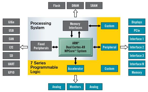
4.5.1 Target Platform
The XBT from MIPS to RISC-V is implemented on an FPGA development board
named PYNQ-Z2. PYNQ refers to “Python Productivity of Zynq”, is an easy-to-use
FPGA board with a Xilinx Zynq-7000 series system-on-chip (SoC) 24 . As shown in
Figure 4.2, a Zynq Chip contains an ARM Cortex-A9 dual-core processor and an
FPGA fabric. They are connected through high-speed AXI interfaces.
Figure 4.2. Zynq 7000 SoC 24
4.5.2 Detailed Design
The tool used for simulation, synthesis and implementation is Xilinx Vivado. The
block design diagram produced by Vivado is shown in Fig.4.3. The source code is
written into the XBT by the Zynq processing system via AXI buses and AXI Smart-
Connect, and the translated target code is read out the same way. In order to gainPrototype Design 19
performance and avoid timing violation, the clock frequency is set to 100 MHz
according to the post-implementation timing report.
Figure 4.3. Block Design of XBT in Vivado
The address mapping and configuration registers are shown in Table 4.9. The
instructions to be translated is first written into the Source Code Buffer area. The
SPC, TPC and the source code length should also be properly set through writing
the corresponding CR fields. After that, a value other than zero can be written into
the Start/Finish Register (SFR), which will start the XBT process. The SFR reads 1 if
the translation process is done, otherwise 0. After translation, the target code can
be read from the Target Code Buffer memory space, and the TPC corresponding
to each SPC can be read from the AMT area. This marks the completion of a whole
translation process.
An example is given as follows. A MIPS bubble sort program has 1159 instruc-
tions and the start address is 0xbfc00000. To translate this program to a RISC-V
program at address 0xc0000000, it needs to be copied to the address space start-
ing with offset 0x0. To configure the XBT system properly, we should write value
0xbfc00000 to register 0x10004, value 1159 to register 0x10008, value 0xc0000000
to register 0x1000C. After that, writing 0x1 into SFR at offset 0x10000 will start the
translation. SFR reads 1 after the translation process is finished, otherwise 0. The
target code can be read or at-speed executed from target code buffer starting at
offset 0x8000, and the AMT is available for look-up at offset 0x4000.Prototype Design 20
Table 4.9. XBT Configuration Registers
Offset (Range) Size R/W Description
0x0000 - 0x3FFF 16KB RW Source Code Buffer (MIPS)
0x4000 - 0x7FFF 16KB RW Address Mapping Table (AMT)
0x8000 - 0xFFFF 32KB RW Target Code Buffer (RISC-V)
0x10000 32bit RW Start/Finish Register (SFR)
0x10004 32bit RW Source PC base
0x10008 32bit RW Source code length
0x1000C 32bit RW Target PC base
0x10010 32bit R Target code length
0x10014 32bit RW Scratch base register config.
0x10018 32bit RW Reallocation register 1 config.
0x1001C 32bit RW Reallocation register 2 config.
0x10020 32bit RW Reallocation register 3 config.5 Results
5.1 Design Reports
The design reports of the whole implemented design on the Zynq platform are
shown in Figure 5.2, 5.3 and 5.1. The reports show that the design has met all the
constraints.
Figure 5.1. Power Report
21Results 22
Figure 5.2. Utilization Report
Figure 5.3. Timing Report
5.2 Benchmark Technique
In order to benchmark the XBT translation time, a software binary translator was
used for comparison. Both translators are run on the Xilinx Zynq platform with
the same ARM processor. Several Testbenches compiled into MIPS binary format
are used to test their performance. The goal of the benchmark is to measure how
many times is a XBT system faster than a software BT system.
5.3 Measurement of Speedup
The terms TBT and TXBT are used to indicate the translation time of the software
BT and XBT respectively. The translation speeds SBT and SXBT can be calculated
by (5.1) and (5.2):
Nsrc
SBT = (5.1)
TBT
Nsrc
SXBT = (5.2)
TXBTResults 23
where Nsrc indicates the number of instructions to be translated. Using (5.1)
and (5.2), the speedup can be calculated by (5.3):
SXBT TBT
Speedup = = (5.3)
SBT TXBT
Different approaches are used to measure TBT and TXBT . TBT and TXBT is cal-
culated by (5.4) and (5.5):
Tend − Tbegin
TBT = (5.4)
1000
Ncycle
TXBT = (5.5)
fclk
In (5.4), Tbegin and Tend are time values in milliseconds from the “clock()” func-
tion in the C library “time.h”. Tbegin is the start time and Tend is the end time. In
order to increase the timing accuracy, the program was repeatedly run 1000 itera-
tions to average out the execution time in microseconds. The time of file I/O and
initialization is deliberately not counted in.
In (5.5), Ncycle is the number of clock cycles of the whole translation process,
and fclk is the frequency of the clock. In this case, fclk = 100MHz.
5.4 Results
The translation time and speedup data are shown in Table 5.1. All measurements
are made on the same Zynq chip. The actual speedup data of the 6 testbenches
vary slightly. This is possibly because the programs have different number of each
type of instructions.
The average speedup is calculated in the last row. It shows that the XBT ap-
proach is approximately 48 times faster than an equivalent software BT approach.Results 24
Table 5.1. Translation Time: BT vs XBT
Bench Nsrc TBT (µs) TXBT (µs) Speedup
Dhrystone 1711 1821.53 40.77 44.68
Bubble Sort 1159 1229.34 24.64 49.89
Select Sort 1123 1192.28 23.90 49.89
Quick Sort 2555 2720.59 59.12 46.02
SHA 3091 3320.32 68.48 48.49
CRC32 1439 1553.18 31.67 49.04
Average 48.006 Conclusions
This work proposed the concept and methodology of the FPGA-based XBT ap-
proach. A prototype of XBT is designed, implemented and tested. It shows an aver-
age speedup of 48 times compared to traditional software BT approaches in several
different testbenches.
XBT proves to provide greater performance and better flexibility compared to
traditional software-based BT. The performance gain comes from the parallelism
brought by the pipeline structure. The FPGA actually has more advantage than
software when running tasks with lots of bitwise operations like instruction decod-
ing.
In addition to the performance gain, the flexibility of XBT can also be very useful.
It is a popular trend that FPGA fabrics are currently embedded in some SoCs. This
technique is called embedded FPGA (eFPGA). The eFPGAs can be programmed
at runtime, enabling the system to switch between different translation configura-
tions when needed to run applications of different ISAs.
With XBT and at-speed execution, we can expect less performance loss when an
application is migrated to another ISA and have to be translated. Even further, we
can expect greater performance in system emulation with XBT, which can narrow
the architectural gap between ISAs.
257 Future Work
The XBT methodology and prototype proposed in this work are still far from ac-
tual practice. This work only discusses the statically linked program as the source
program. However, dynamically-linked program is more common in modern sys-
tems, which should be taken into consideration. Adjustments and optimizations
need to be made to detect and translate dynamic link libraries. Cache coherency
problems could also occur when XBT is working with multiple target processors.
More measures need to be taken to solve the coherency problem.
Due to the limited time and capability, this work did not really involve a real
RISC-V processor to test the validity and efficiency when executing the translated
code at-speed. This is truly a pity. It is expected that more works on bringing XBT
to practice and adapt it to different source and target ISAs are done in the future.
26References
[1] Erik R Altman and Kemal Ebcioglu. Full system binary translation: Risc to vliw.
IBM, Yorktown Heights, NY, Tech. Rep. RC23262, 2000.
[2] Erik R Altman, David Kaeli, and Yaron Sheffer. Welcome to the opportunities
of binary translation. Computer, 33(3):40–45, 2000.
[3] Marc Angelone. Approaches for Universal Static Binary Translation. PhD the-
sis, Citeseer, 2006.
[4] Sorav Bansal and Alex Aiken. Binary translation using peephole superopti-
mizers. In OSDI, volume 8, pages 177–192, 2008.
[5] Fabrice Bellard. Qemu, a fast and portable dynamic translator. In USENIX
annual technical conference, FREENIX Track, volume 41, page 46. Califor-nia,
USA, 2005.
[6] Edson Borin and Youfeng Wu. Characterization of dbt overhead. In 2009 IEEE
International Symposium on Workload Characterization (IISWC), pages 178–
187. IEEE, 2009.
[7] Matthew Chapman, Daniel J Magenheimer, and Parthasarathy Ranganathan.
Magixen: Combining binary translation and virtualization. HP Enterprise Sys-
tems and Software Laboratory, pages 1–15, 2007.
[8] Jiunn-Yeu Chen, Wuu Yang, Tzu-Han Hung, Hong-Men Su, and Wei-Chung
Hsu. A static binary translator for efficient migration of arm-based applica-
tions. In Workshop on Optimizations for DSP and Embedded Systems, pages
36–39. Citeseer, 2008.
[9] Anton Chernoff, Mark Herdeg, Ray Hookway, Chris Reeve, Norman Rubin,
Tony Tye, S Bharadwaj Yadavalli, and John Yates. Fx! 32: A profile-directed
binary translator. IEEE Micro, 18(02):56–64, 1998.
[10] Cristina Cifuentes and Vishv M Malhotra. Binary translation: Static, dynamic,
retargetable? In icsm, volume 96, pages 340–349, 1996.
[11] Cristina Cifuentes and Mike Van Emmerik. Uqbt: Adaptable binary transla-
tion at low cost. Computer, 33(3):60–66, 2000.
27Future Work 28
[12] Kemal Ebcioglu, Erik Altman, Michael Gschwind, and Sumedh Sathaye. Dy-
namic binary translation and optimization. IEEE Transactions on Computers,
50(6):529–548, 2001.
[13] Byron Hawkins, Brian Demsky, Derek Bruening, and Qin Zhao. Optimizing
binary translation of dynamically generated code. In 2015 IEEE/ACM Interna-
tional Symposium on Code Generation and Optimization (CGO), pages 68–78.
IEEE, 2015.
[14] MIPS Technologies Inc. MIPS® Architecture For Programmers Volume I-A:
Introduction to the MIPS32® Architecture, 2011. Revision 3.02.
[15] MIPS Technologies Inc. MIPS® Architecture For Programmers Volume II-A:
The MIPS32® Instruction Set, 2011. Revision 3.02.
[16] Apple Insider. Rosetta 2. Website. https://appleinsider.com/inside/
rosetta-2 Accessed Jun 14, 2021.
[17] Ian Kuon and Jonathan Rose. Measuring the gap between fpgas and asics.
IEEE Transactions on computer-aided design of integrated circuits and systems,
26(2):203–215, 2007.
[18] Mathias Payer and Thomas Gross. Fast binary translation: Translation effi-
ciency and runtime efficiency. In 2nd Workshop on Architectural and Microar-
chitectural Support for Binary Translation (AMAS-BT’09), Austin, Texas, USA,
2009.
[19] Mark Probst. Dynamic binary translation. In UKUUG Linux Developer’s Con-
ference, volume 2002, 2002.
[20] Simon Rokicki, Erven Rohou, and Steven Derrien. Hardware-accelerated dy-
namic binary translation. In Design, Automation & Test in Europe Conference
& Exhibition (DATE), 2017, pages 1062–1067. IEEE, 2017.
[21] Simon Rokicki, Erven Rohou, and Steven Derrien. Hybrid-dbt: Hard-
ware/software dynamic binary translation targeting vliw. IEEE Transactions
on Computer-Aided Design of Integrated Circuits and Systems, 38(10):1872–
1885, 2018.
[22] Richard L Sites, Anton Chernoff, Matthew B Kirk, Maurice P Marks, and Scott G
Robinson. Binary translation. Communications of the ACM, 36(2):69–81, 1993.Future Work 29
[23] Matthew Smithson, Khaled ElWazeer, Kapil Anand, Aparna Kotha, and Rajeev
Barua. Static binary rewriting without supplemental information: Overcom-
ing the tradeoff between coverage and correctness. In 2013 20th Working Con-
ference on Reverse Engineering (WCRE), pages 52–61. IEEE, 2013.
[24] Xilinx. Python productivity for Zynq (Pynq) Documentation, 2020. Release 2.5.
[25] Yuan Yao, Zhongyong Lu, Qingsong Shi, and Wenzhi Chen. Fpga based
hardware-software co-designed dynamic binary translation system. In 2013
23rd International Conference on Field programmable Logic and Applications,
pages 1–4. IEEE, 2013.
[26] Cindy Zheng and Carol Thompson. Pa-risc to ia-64: Transparent execution,
no recompilation. Computer, 33(3):47–52, 2000.You can also read