KSB IE3-Motor Installation/Operating Manual - Asynchronous Motor - KSB Web-Shop
←
→
Page content transcription
If your browser does not render page correctly, please read the page content below
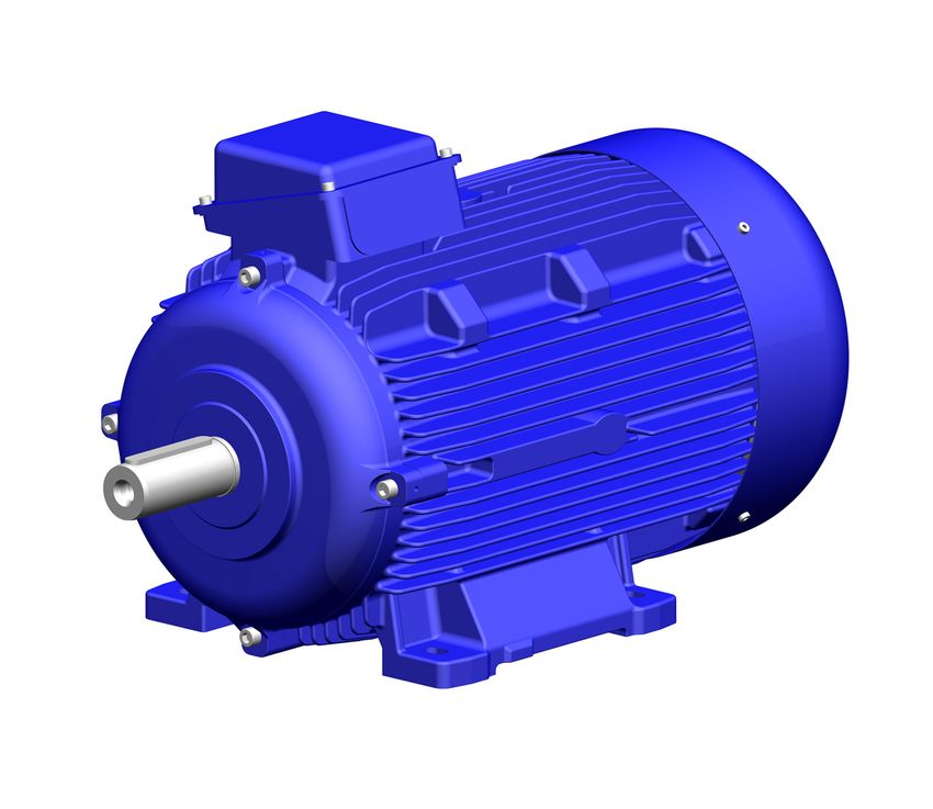
Asynchronous Motor

KSB IE3-Motor
0.55 kW to 132 kW
2-pole, 4-pole

Installation/Operating Manual
Legal information/Copyright
Installation/Operating Manual KSB IE3-Motor

Original operating manual

All rights reserved. The contents provided herein must neither be distributed, copied, reproduced,
edited or processed for any other purpose, nor otherwise transmitted, published or made available to a
third party without the manufacturer's express written consent.
Subject to technical modification without prior notice.

© KSB SE & Co. KGaA, Frankenthal 04/03/2019
Contents

                                        Contents
1   General.................................................................................................................................................... 6
    1.1    Principles ...........................................................................................................................................................   6
    1.2    Target group.....................................................................................................................................................        6
    1.3    Other applicable documents............................................................................................................................                   6
    1.4    Symbols .............................................................................................................................................................    6

2   Safety ...................................................................................................................................................... 7
    2.1    Key to safety symbols/markings.......................................................................................................................                    7
    2.2    General..............................................................................................................................................................    7
    2.3    Intended use .....................................................................................................................................................       8
    2.4    Personnel qualification and training...............................................................................................................                      8
    2.5    Consequences and risks caused by non-compliance with this manual .........................................................                                               8
    2.6    Safety awareness ..............................................................................................................................................          8
    2.7    Safety information for the user/operator .......................................................................................................                         8
    2.8    Safety information for maintenance, inspection and installation ................................................................                                         9
    2.9    Unauthorised modes of operation ..................................................................................................................                       9
    2.10   Electromagnetic compatibility.........................................................................................................................                   9

3   Transport/Temporary Storage/Disposal............................................................................................. 10
    3.1    Checking the condition upon delivery ..........................................................................................................                        10
    3.2    Transport.........................................................................................................................................................     10
    3.3    Storage/preservation ......................................................................................................................................            10
    3.4    Disposal ...........................................................................................................................................................   11

4   Description............................................................................................................................................ 12
    4.1    General description ........................................................................................................................................           12
    4.2    Designation.....................................................................................................................................................       12
    4.3    Name plate......................................................................................................................................................       13
    4.4    Types of construction .....................................................................................................................................            13
    4.5    Mounting arrangements................................................................................................................................                  14
    4.6    Noise characteristics .......................................................................................................................................          14
    4.7    Balancing.........................................................................................................................................................     14

5   Installation at Site ................................................................................................................................ 15
    5.1    Checks to be carried out prior to installation...............................................................................................                          15
    5.2    Installing the motor........................................................................................................................................           16
    5.3    Electrical connection ......................................................................................................................................           17
           5.3.1 Motor connection inside the terminal box ......................................................................................                                  17
           5.3.2 Checking the direction of rotation ...................................................................................................                           19
    5.4    Tightening torques.........................................................................................................................................            20
    5.5    Installing and removing output components ...............................................................................................                              21

6   Commissioning/Start-up/Shutdown................................................................................................... 22
    6.1    Checking earth conductor connection ..........................................................................................................                         22
    6.2    Checking insulation resistance.......................................................................................................................                  22
    6.3    Prerequisites for commissioning/start-up......................................................................................................                         22
    6.4    Start-up ...........................................................................................................................................................   23
    6.5    Operating limits..............................................................................................................................................         23
           6.5.1 Voltages and frequencies ..................................................................................................................                      23
           6.5.2 Maximum permissible speed .............................................................................................................                          23
           6.5.3 Ambient temperature........................................................................................................................                      23
           6.5.4 Altitude...............................................................................................................................................          23
    6.6    Shutdown........................................................................................................................................................       23
    6.7    Idle periods .....................................................................................................................................................     24
    6.8    Returning to service .......................................................................................................................................           24

                                        KSB IE3-Motor                                                                                                                   3 of 40
Contents
7 Servicing/Maintenance ........................................................................................................................ 25
7.1 Safety regulations........................................................................................................................................... 25
7.2 Maintenance/inspection................................................................................................................................. 26
7.2.1 Supervision of operation ................................................................................................................... 26
7.2.2 Inspection ........................................................................................................................................... 27
7.3 Preparing disassembly .................................................................................................................................... 30
7.4 Dismantling the motor................................................................................................................................... 30
7.4.1 General information/Safety regulations........................................................................................... 30
7.4.2 Removing the protective roof (optional) ......................................................................................... 31
7.4.3 Dismantling the fan hood ................................................................................................................. 31
7.4.4 Dismantling the fan ........................................................................................................................... 31
7.4.5 Dismantling the rotor ........................................................................................................................ 31
7.4.6 Dismantling the bearings .................................................................................................................. 31
7.5 Assembling the motor.................................................................................................................................... 32
7.5.1 Fitting the bearings ........................................................................................................................... 32
7.5.2 Installing the rotor............................................................................................................................. 33
7.5.3 Mounting the fan .............................................................................................................................. 33
7.5.4 Mounting the fan hood..................................................................................................................... 33
7.5.5 Mounting the protective roof (optional) ......................................................................................... 33
8 Trouble-shooting.................................................................................................................................. 34
9 EU Declaration of Conformity ............................................................................................................. 35
Index ..................................................................................................................................................... 36
4 of 40 KSB IE3-MotorGlossary
Glossary
Drive end
End of motor with bare shaft end for connecting
the machine to be driven via a coupling or traction
sheave and belt (driven output or machine
element).
Non-drive end
End of motor with fan and fan hood.
KSB IE3-Motor 5 of 401 General
1 General
1.1 Principles
This operating manual is valid for the type series and variants indicated on the front
cover.
The operating manual describes the proper and safe use of this equipment in all
phases of operation.
The name plate indicates the type series, the main operating data and the serial
number. The serial number uniquely describes the product and is used as
identification in all further business processes.
In the event of damage, immediately contact your nearest KSB Service centre to
maintain the right to claim under warranty.
1.2 Target group
This operating manual is aimed at the target group of trained and qualified specialist
technical personnel.
1.3 Other applicable documents
Table 1: Overview of other applicable documents
Document Contents
Operating manual(s) for the Proper and safe use of the pump in all phases of
pump(s) operation
Wiring diagram Electrical connection
For accessories and/or integrated machinery components, observe the relevant
manufacturer's product literature.
1.4 Symbols
Table 2: Symbols used in this manual
Symbol Description
✓ Conditions which need to be fulfilled before proceeding with the
step-by-step instructions
⊳ Safety instructions
⇨ Result of an action
⇨ Cross-references
1. Step-by-step instructions
2.
Note
Recommendations and important information on how to handle
the product
6 of 40 KSB IE3-Motor2 Safety
2 Safety
All the information contained in this section refers to hazardous situations.
! DANGER
In addition to the present general safety information the action-related safety
information given in the other sections must be observed.
2.1 Key to safety symbols/markings
Table 3: Definition of safety symbols/markings
Symbol Description
! DANGER DANGER
This signal word indicates a high-risk hazard which, if not avoided,
will result in death or serious injury.
! WARNING WARNING
This signal word indicates a medium-risk hazard which, if not
avoided, could result in death or serious injury.
CAUTION CAUTION
This signal word indicates a hazard which, if not avoided, could
result in damage to the machine and its functions.
General hazard
In conjunction with one of the signal words this symbol indicates a
hazard which will or could result in death or serious injury.
Electrical hazard
In conjunction with one of the signal words this symbol indicates a
hazard involving electrical voltage and identifies information about
protection against electrical voltage.
Machine damage
In conjunction with the signal word CAUTION this symbol indicates
a hazard for the machine and its functions.
2.2 General
▪ This operating manual contains general installation, operating and maintenance
instructions that must be observed to ensure safe operation of the system and
prevent personal injury and damage to property.
▪ Comply with all the safety instructions given in the individual sections of this
operating manual.
▪ The operating manual must be read and understood by the responsible specialist
personnel/operators prior to installation and commissioning.
▪ The contents of this operating manual must be available to the specialist
personnel at the site at all times.
▪ Information and markings attached directly to the product must always be
complied with and kept in a perfectly legible condition at all times. This applies
to, for example:
– Markings for connections
– Name plate
▪ The operator is responsible for ensuring compliance with all local regulations not
taken into account.
▪ The motor has been designed and constructed in accordance with the
requirements of Directive 2014/35/EU (“Low-voltage Directive”). The motor is
intended for use in industrial plants.
▪ If the motor is used in countries outside the European Community, adhere to the
regulations applicable to the relevant country. Also observe any local and
industry-specific regulations governing installation and safety.
KSB IE3-Motor 7 of 402 Safety
2.3 Intended use
▪ This product must only be operated within the limit values stated in the technical
product literature for the mains voltage, mains frequency, ambient temperature,
motor rating, speed, density, pressure, temperature and in compliance with any
other instructions provided in the operating manual or other applicable
documents.
▪ The product must not be used in potentially explosive atmospheres.
2.4 Personnel qualification and training
▪ All personnel involved must be fully qualified to install, operate, maintain and
inspect the product this manual refers to.
▪ The responsibilities, competence and supervision of all personnel involved in
transport, installation, operation, maintenance and inspection must be clearly
defined by the operator.
▪ Deficits in knowledge must be rectified by means of training and instruction
provided by sufficiently trained specialist personnel. If required, the operator can
commission the manufacturer/supplier to train the personnel.
▪ Training on the product must always be supervised by specialist technical
personnel.
2.5 Consequences and risks caused by non-compliance with this manual
▪ Non-compliance with these operating instructions will lead to forfeiture of
warranty cover and of any and all rights to claims for damages.
▪ Non-compliance can, for example, have the following consequences:
– Hazards to persons due to electrical, thermal, mechanical and chemical
effects and explosions
– Failure of important product functions
– Failure of prescribed maintenance and servicing practices
– Hazard to the environment due to leakage of hazardous substances
2.6 Safety awareness
In addition to the safety information contained in this operating manual and the
intended use, the following safety regulations shall be complied with:
▪ Accident prevention, health regulations and safety regulations
▪ Safety regulations for handling hazardous substances
▪ Applicable standards, directives and laws
2.7 Safety information for the user/operator
▪ Fit protective equipment (e.g. contact guards) supplied by the operator for hot,
cold or moving parts, and check that the equipment functions properly.
▪ Do not remove any protective equipment (e.g. contact guards) during operation.
▪ Provide the personnel with protective equipment and make sure it is used.
▪ Eliminate all electrical hazards. (In this respect refer to the applicable national
safety regulations and/or regulations issued by the local energy supply
companies.)
8 of 40 KSB IE3-Motor2 Safety 2.8 Safety information for maintenance, inspection and installation ▪ Modifications or alterations of the pump (set) are only permitted with the manufacturer's prior consent. ▪ Use only original spare parts or parts/components authorised by the manufacturer. The use of other parts/components can invalidate any liability of the manufacturer for resulting damage. ▪ The operator ensures that maintenance, inspection and installation are performed by authorised, qualified specialist personnel who are thoroughly familiar with the manual. ▪ Any work on the product shall only be performed when it has been disconnected from the power supply (de-energised). ▪ Carry out work on the product during standstill only. ▪ As soon as the work has been completed, re-install and re-activate any safety- relevant devices and protective devices. Before returning the product to service, observe all instructions on commissioning. 2.9 Unauthorised modes of operation Never operate the product outside the limits stated in the data sheet and in this manual. The warranty relating to the operating reliability and safety of the product supplied is only valid if the product is used in accordance with its intended use. 2.10 Electromagnetic compatibility When operating the motor on a frequency inverter always observe the frequency inverter manufacturer's information on compliance with the Electromagnetic Compatibility Directive. Take additional measures to ensure compliance with the Directive and obtain a connection approval from the local energy supply company, if necessary. KSB IE3-Motor 9 of 40
3 Transport/Temporary Storage/Disposal

                                 3 Transport/Temporary Storage/Disposal

                                 3.1 Checking the condition upon delivery
                                   1. On transfer of goods, check each packaging unit for damage.
                                   2. In the event of in-transit damage, assess the exact damage, document it and
                                      notify KSB or the supplying dealer and the insurer about the damage in writing
                                      immediately.

                                 3.2 Transport

                                       DANGER
                                  Improper transport
                                  Danger to life from falling parts!
                                    ▷ Only transport the motor in the specified position.
                                    ▷ Always use all lifting lugs available at the motor during transport.
                                    ▷ Always screw in lifting lugs (lifting eyebolts) up to the contact face and tighten.
                                    ▷ Use suitable, permitted lifting accessories.

                                 Only remove any transport locks provided prior to commissioning and store or
                                 disable. Use transport locks for additional transport tasks or re-enable.
                                 To transport motors weighing more than 25 kg, suspend them from the lifting tackle
                                 as shown.

                                 Fig. 1: Transporting the motor by two lifting lugs attached to sides of motor housing

                                 3.3 Storage/preservation
     Exposed machined metal Exposed locating surfaces (shaft ends, flange faces, centring spigots, connector
                    surfaces contacts) are treated with a layer of temporary corrosion protection (< 6 months) for
                             transport. Take suitable corrosion protection measures for extended storage periods.
                Storage period Rotate the shaft once annually to avoid permanent standstill markings. Extended
                               storage periods decrease the service life (increase ageing) of the grease applied to
                               the rolling element bearings.
       Closed rolling element Replace closed rolling element bearings after 48 months of storage.
                     bearings
        Condensation during To prevent condensation inside the motor, switch on the motor standstill heater1).
                    storage
                            If condensation water has formed and a drain hole is provided, position the motor in
                            such a way that the water drain plug is at the lowest point of the housing. Drain off
                            the condensation water. (ð Section 7.2.2.1, Page 28)

1)     If any

10 of 40                         KSB IE3-Motor
3 Transport/Temporary Storage/Disposal
Drain off the condensation water as required by the ambient conditions but at least
every 6 months.
Outdoor storage
CAUTION
Damage during storage due to humidity, dirt or vermin
Corrosion/contamination of the drive!
▷ Cover all components with water-proof material. Covers or tarpaulins must not
contact the surface of the stored goods.
▷ Ensure sufficient air circulation, e.g. by inserting wooden spacers.
▷ To ensure protection against ground moisture, arrange motors and packaged
motors on pallets, bars or foundations.
▷ Prevent the possibility of the product sinking into the ground.
Implement appropriate measures to accommodate extreme climatic conditions, e.g.
salty, dusty or moist atmospheres.
Indoor storage
Storage rooms should provide protection against extreme weather conditions and be
dry, dust-free, frost-free, jolt-free, vibration-free and well ventilated.
3.4 Disposal
Electrical or electronic equipment marked with the adjacent symbol must not be
disposed of in household waste at the end of its service life.
Contact your local waste disposal partner for returns.
If the used electrical or electronic equipment contains personal data, the user is
responsible for deleting it before the equipment is returned.
Due to some components, the product is classified as special waste.
1. Dismantle the product.
2. Separate and sort the materials, e.g. by:
- Metals
- Plastics
- Electronic waste
- Greases and other lubricants
3. Dispose of materials in accordance with local regulations or in another
controlled manner. PCBs, power electronics, capacitors and electronic
components are all hazardous waste.
KSB IE3-Motor 11 of 404 Description
4 Description
4.1 General description
Low-voltage asynchronous motor of efficiency class IE3 to IEC 60034-30 for operation
on the public power grid or on a frequency inverter.
4.2 Designation
Table 4: Designation example
Position
1 2 3 4 5 6 7 8 9 10 11 12 13 14 15 16 17 18 19 20 21 22 23 24 25 26 27 28 29 30
- 2 - 4 5 , 0 - 2 2 5 M - B W A 6 F 3 N T S D W F U W K S W
Table 5: Designation key
Position Code Description
1-2 Number of poles
2 2 poles
4 4 poles
4-7 Rated power
45,0 45 kW (0.55 ... 45.0 kW)
9-12 IEC size
2 2 5 M Shaft centreline height [mm] = IEC size
14 Enclosure
B IP55
15 Type of protection
W Non-explosionproof
16 Rated voltage and rated frequency
A 3~, AC, 220 VΔ, 380 VY, 50 Hz
17 Efficiency class
6 IE3
18 Thermal class
F Thermal class F
19 Motor and winding protection
3 3 PTCs
20 Direction of rotation
N Clockwise and counter-clockwise (bi-directional)
21 Position of terminal box
T Terminal box on top
22 Feet attached by bolts
S Feet attached by bolts
W Without feet
H Integrally cast feet
23 Position of fixed bearing
D Fixed bearing, drive end
24 Protective roof
W Without protective roof
25 Motor flange
F EN 50347 Type FF
W Without flange
26 Operation on inverter
U Operation on inverter permitted
27 Approval
12 of 40 KSB IE3-Motor4 Description
Position Code Description
27 W Without approvals
28-29 Manufacturer
KS KSB
30 Manufacturer type
W KSB IE3 Motor
4.3 Name plate
The name plate provides, as a minimum, the following information:
▪ Manufacturer: KSB SE & Co. KGaA, Johann-Klein-Straße 9, 67227 Frankenthal
▪ KSB material number
▪ Type designation: KSB IE3 Motor
▪ Year of construction
▪ Number of phase windings
▪ Standards for design
▪ Enclosure
▪ Efficiency class to IEC 60034-30
▪ Thermal class
▪ Rated power/ rated powers
▪ Rated voltage/ rated voltages
▪ Rated frequency/ rated frequencies
▪ Rated current/ rated currents
▪ Rated speed/ rated speeds
▪ Rated power factor/ rated power factors
▪ Total weight
4.4 Types of construction
The motors are available in different types of construction:
Table 6: Types of construction and installation variants
Type of construction Shaft centreline IM codes
Flange type2) With height
foot [mm]
None ✘ 71 to 315 B3
Flange with clearance - 71 to 112 V1, B5
holes (FF) ✘ 132 to 315 V153), B35
2) Designations to EN 50347
3) Detachable feet
KSB IE3-Motor 13 of 404 Description
4.5 Mounting arrangements
IM codes Illustration
IM B3
IM B5
IM B35
IM V1
IM V15
4.6 Noise characteristics
The noise characteristics stipulated by DIN EN 60034-9 are complied with.
4.7 Balancing
The rotor is balanced dynamically in accordance with the ISO 1940-1 standard. The
rotor is balanced to balance quality grade G 2.5.
The motor complies with vibration class A to IEC 60034-14.
Marking
▪ For motors with key, the rotors are balanced dynamically with a half key ("H") as
standard in accordance with ISO 21940-32 requirements. The output element
must also be balanced with a half key in accordance with the key convention.
14 of 40 KSB IE3-Motor5 Installation at Site
5 Installation at Site
5.1 Checks to be carried out prior to installation
Place of installation
WARNING
Installation on mounting surface which is unsecured and cannot support the load
Personal injury and damage to property!
▷ Use a concrete of compressive strength class C12/15 which meets the
requirements of exposure class XC1 to EN 206-1.
▷ The mounting surface must be set, flat, and level.
▷ Observe the weights indicated.
1. Check the structural requirements.
All structural work required must have been prepared in accordance with the
dimensions stated in the outline drawing/general arrangement drawing.
Protective roof/additional Install a protective roof or additional roofing for vertical installation.
roofing
Vertical installation ▪ For vertical installation with the shaft end pointed downwards to prevent
foreign objects from falling into the fan hood.
▪ For vertical installation with the shaft end pointed upwards to prevent fluid
ingress along the length of the shaft.
Outdoor installation Shield the motor by implementing suitable protection measures in order to prevent
condensation from forming and to avoid the long-term effects caused by direct
exposure to sunlight, rain, snow, ice and dust.
Flatness tolerance of contact surfaces
For foot-mounted motors, adhere to the following flatness tolerance of the contact
surfaces for the motor feet.
Table 7: Flatness tolerance of contact surfaces for motor feet
Shaft centreline height Flatness tolerance (mm)
≤ 132 mm 0,10
≥ 160 mm 0,15
Ventilation
WARNING
Improper installation
Drive overheated!
▷ Maintain the specified minimum distances to neighbouring assemblies.
▷ Never restrict the ventilation ducting to/from the drive.
▷ Prevent exhaust air from neighbouring assemblies from being drawn in directly.
X
Fig. 2: Minimum distance X
KSB IE3-Motor 15 of 405 Installation at Site
Table 8: Minimum distance X to neighbouring assemblies
Motors with shaft centreline height [mm] Minimum distance X [mm]
71 - 100 30
112 - 132 40
160 - 180 50
200 - 225 60
Condensation water drain If a drain hole is provided, position the motor in such a way that the water drain plug
is at the lowest point of the housing. The motor is supplied with the water drain plug
closed.
5.2 Installing the motor
Checks prior to installation work
▪ Repair any damage to the paintwork. (ð Section 7.2.2.2, Page 28)
▪ Remove any anti-corrosives applied to exposed metal parts that are required to
ensure proper assembly or installation.
Alignment and fastening
NOTE
Maintain the vibration levels to ISO 10816-1 during operation.
Observe the following when aligning and fastening:
▪ Ensure that the motor feet are resting evenly on the support surface.
▪ Ensure that feet and flanges are mounted as specified in the manual.
▪ Avoid rigid couplings.
▪ Ensure precise alignment for direct coupling.
▪ Ensure that mounting surfaces are free from contamination.
▪ Avoid resonances caused by the structure at the rotational frequency and double
mains frequency.
▪ Unusual noise that may occur when rotating the rotor by hand.
Compensation of radial The following measures are required to compensate radial misalignment at the
misalignment at the coupling and horizontally adjust the motor in relation to the driven machine (e.g. the
coupling and horizontal pump):
adjustment ▪ Vertical positioning
To avoid distortion (warping) of the driven machine and the motor, place thin
metal sheets under the motor feet.
The number of shims should be restricted to a minimum, in other words, they
should only be stacked if this is unavoidable.
▪ Horizontal positioning
For horizontal positioning, laterally shift the motor on the foundation while
maintaining axial alignment (to prevent angular misalignment).
Ensure a uniform circumferential axial clearance at the coupling when
positioning.
▪ Smooth running characteristics
A stable, vibration-free foundation to DIN 4024, exact alignment of the coupling
and a well-balanced output element (coupling, pulley, fan, etc.) are prerequisites
for smooth, vibration-free operation of the motor.
Complete balancing of the motor with the output element may be required.
Note the information and evaluation criteria to ISO 10816.
▪ Foot/flange mounting
Use the thread sizes specified by EN 50347 for fastening the foot and flange of
the motor to the foundation and to the motor flange respectively. Fasten the
motor at four foot holes or flange bolt holes positioned in rectangular
arrangement to each other. The customer is responsible for selecting the
16 of 40 KSB IE3-Motor5 Installation at Site
strength of the fastening elements.
Property class recommendations: Class 5.6 or higher for fastening elements for
motors with shaft centreline height up to and including 160 mm, and class 8.8 or
higher for motors with shaft centreline height 180 mm.
NOTE
Lifting lugs that have been screwed in must either be tightened or removed after
installation.
5.3 Electrical connection
DANGER
Hazardous voltage
Danger of death from electric shock!
▷ Have all work performed only by qualified specialist personnel and only when
the drive is at a standstill and secured against unintentional start-up. This also
applies to auxiliary circuits (e.g. standstill heater).
▷ The drive must not be electrically connected at any point in time when work is
performed on the open terminal box.
WARNING
Incorrect connection to the mains
Damage to the mains network, short circuit!
▷ Observe the technical specifications of the local energy supply companies.
NOTE
Always protect three-phase motors with a current-dependent overload protection
device with additional phase failure protection.
Select the motor connection cables in accordance with IEC 60364, taking into account
the current load of the cable at the given ambient temperature and the requisite
heat dissipation to IEC / EN 60204-1 as a result of cable routing.
5.3.1 Motor connection inside the terminal box
Observe the following when performing any work on the terminal box:
▪ Always use the original sealing element to close the terminal box so that it is dust
tight and watertight.
▪ Do not damage any components inside the terminal box, such as terminal board
and cable connections.
▪ Ensure that no foreign matter, contamination or moisture are present in the
terminal box. Terminal box cable entries to DIN 42925.
▪ Close additional open cable entries, using O-rings or suitable gaskets.
▪ Observe prescribed tightening torques for cable glands and other screws/bolts.
▪ When retrofitting cable glands to safeguard the required level of enclosure
protection, ensure that the gasket is seated properly on the outside of the
terminal box.
Connecting the motor
1. Check the electrical voltage of the available power supply network against the
data on the motor name plate.
2. Connect the earth conductor (PE).
KSB IE3-Motor 17 of 405 Installation at Site
3. Knock out any knock-out openings in the terminal box. While doing this, avoid
causing damage to the terminal board, cable connections, etc. inside the
terminal box.
4. Connect the motor in star configuration or delta configuration in accordance
with the rated voltage (see name plate) and the available power supply
network. Alternatively, the 6-core connection of the three windings can be
connected to an external switchgear for automatic switchover.
Fig. 3: Star configuration
Fig. 4: Delta configuration
ð The terminal boards of motors with shaft centreline heights of 80 mm and
90 mm may differ from the schematic shown. In this case, star configuration
or delta configuration is selected by setting jumpers.
5. Optionally, the 2-core connection of the series-connected PTC thermistors for
temperature monitoring of the motor can be connected to terminals 1T1 and
1T2 with a suitable thermistor relay (PTC thermistor tripping unit). Observe the
maximum measuring voltage!
18 of 40 KSB IE3-Motor5 Installation at Site
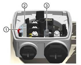
Changing the jumpers
Fig. 5: Jumper position
1. Disengage the red locking lever (1) and pull the jumper (2) out of the slot.
2. Undo the snap hook at the storage pocket and take out the jumper (3).
3. Push the jumper (3) into the slot until it rests on the bottom. Engage the locking
lever again.
4. Place the jumper (2) into the storage pocket and engage the snap hook.
5.3.2 Checking the direction of rotation
WARNING
Parts flying off
Personal injury and damage to property!
▷ When checking the direction of rotation with the coupling removed, secure the
respective keys to protect them from being thrown off.
The motors are configured for clockwise and anti-clockwise rotation as standard.
Select the drive's direction of rotation to match the direction of rotation required by
the driven centrifugal pump.
Clockwise rotation Connecting the power cables in the phase sequence U1, V1, W1 to L1, L2, L3 of the
power supply network results in clockwise rotation (looking at the drive shaft end).
Anti-clockwise rotation Interchanging two connections, e.g. V1, U1, W1 to L1, L2, L3 results in anti-clockwise
rotation.
KSB IE3-Motor 19 of 405 Installation at Site
5.4 Tightening torques
Unless other tightening torques are indicated on the motor the following torques
shall be used:
Table 9: Tightening torques for terminal board connections
Thread [Nm]
M4 2,0
M5 3,0
M6 5,0
M8 10
Table 10: Tightening torques for terminal board fastening elements
Thread [Nm]
M4 2,0
M5 4,0
M6 9,0
M8 23
Table 11: Tightening torques for terminal box cover
Thread [Nm]
M5 4,0
M6 7,0
M8 19
M10 37
M12 63
Table 12: Tightening torques for strain relief fasteners
Thread [Nm]
M12 1,5
M16 2,0
M20 4,0
M25 4,0
M32 6,0
M40 6,0
M50 6,0
M63 8,0
Table 13: Tightening torques for earth conductor, bearing cover, fan hood, foot in
aluminium material variant
Thread [Nm]
M4 2,0
M5 4,5
M6 7,5
M8 19
M10 37
M12 64
Table 14: Tightening torques for earth conductor, bearing cover, fan hood, foot in
grey cast iron material variant
Thread [Nm]
M4 3,0
M5 6,0
M6 10
M8 25
20 of 40 KSB IE3-Motor5 Installation at Site Thread [Nm] M10 50 M12 86 5.5 Installing and removing output components ▪ Please also note the information about installing output components in the operating manual of the driven machine (e.g. pump). ▪ To install output components (coupling, pulley, etc.), use the thread on the shaft end and heat up the components if necessary. ▪ Use an appropriate device for removal. ▪ Do not apply hard impacts (e.g. with a hammer or similar) when installing and removing. ▪ Observe the maximum permissible radial and axial forces transmitted via the shaft end to the rolling element bearing and do not exceed them. KSB IE3-Motor 21 of 40
6 Commissioning/Start-up/Shutdown

           6 Commissioning/Start-up/Shutdown

                 DANGER
            Hazardous voltage
            Danger of death from electric shock!
              ▷ Have all work performed only by qualified specialist personnel and only when
                the drive is at a standstill and secured against unintentional start-up. This also
                applies to auxiliary circuits (e.g. standstill heater).
              ▷ The drive must not be electrically connected at any point in time when work is
                performed on the open terminal box.

           Before commissioning and whenever returning the product to service, perform the
           electrical safety checks stipulated by EN 60204-1.

           6.1 Checking earth conductor connection
           Check that the earth conductor has been correctly connected in accordance with
           EN60204.

           6.2 Checking insulation resistance
           Prior to commissioning and following prolonged storage or standstill periods, the
           insulation resistance will need to be checked and verified.

             NOTE
            If windings have been dried after having been repaired or cleaned, bear in mind
            that the insulation resistance of warm windings is lower. The insulation resistance
            can only be correctly evaluated after converting to the reference temperature of
            25 °C.

           The insulation resistance of the stator winding must equal at least 1.5 megohms in
           motors for 220 -1000 V.

           6.3 Prerequisites for commissioning/start-up
           Before commissioning/starting up the drive, make sure the following conditions are
           met:
            ▪ The drive has been properly installed and aligned.
            ▪ The drive has been connected correctly for the specified direction of rotation.
            ▪ The operating conditions correspond to the data provided on the name plate.
            ▪ The output elements have been correctly configured depending on type (e.g.
              alignment and balancing of couplings, belt forces for belt drive, tooth forces and
              tooth flank clearance for gearwheel drive, radial and axial clearance for coupled
              shafts).
            ▪ The earthing and equipotential bonding connections have been properly made.
            ▪ All fastening bolts, connecting elements, and electrical connections have been
              properly tightened to the specified tightening torques.
            ▪ Screwed-in lifting lugs have been removed following installation or secured
              against working loose.
            ▪ The shaft rotates freely.
            ▪ Measures have been taken to prevent accidental contact with moving and live
              parts.
            ▪ The unused shaft end has been covered and the key secured to prevent it from
              being thrown off.
            ▪ Components (cables, etc.) that are sensitive to temperature do not come into
              contact with the motor housing.

22 of 40   KSB IE3-Motor
6 Commissioning/Start-up/Shutdown
6.4 Start-up
WARNING
High sound pressure level > 70 dB(A) can occur during operation
Injury to the ear and hearing impairment. Hardness of hearing, tinnitus and hearing
loss can be caused!
▷ Wear ear protection!
▷ Observe the applicable local occupational health and safety regulations.
The motor must only be started from a standstill.
1. Re-check the direction of rotation immediately after starting.
(ð Section 5.3.2, Page 19)
6.5 Operating limits
6.5.1 Voltages and frequencies
Motor operation off the rated point will cause a rise in motor temperature. A voltage
tolerance of ± 5 % and a frequency tolerance of ± 2 % are permissible.
Any situation where both the voltage and the frequency tolerance apply
simultaneously shall be governed by the provisions of range A as described in
EN60034-1. The motors can be operated continuously in range A. In accordance with
EN60034-1, prolonged operation in range B is not recommended.
6.5.2 Maximum permissible speed
Comply with the rotational speed indicated on the name plate.
6.5.3 Ambient temperature
CAUTION
Operation outside the permissible ambient temperature
Damage to the pump (set)!
▷ Observe the specified limits for permissible ambient temperatures.
Observe the following parameters and values during operation:
Table 15: Permissible ambient temperatures
Permissible ambient temperature Value
Maximum 40 °C
Minimum - 20 °C
6.5.4 Altitude
▪ ≤ 1000 m above MSL: without power derating
▪ > 1000 m above MSL: installation at altitudes of up to 4000 m above MSL is
possible with power derated by 3.8 % per 500 m.
6.6 Shutdown
The motor is only regarded as being shut down if it has been de-energised and the
shaft has stopped rotating.
KSB IE3-Motor 23 of 406 Commissioning/Start-up/Shutdown
6.7 Idle periods
Extended idle periods (> 1 month)
For extended idle periods (> 1 month), start up the drive regularly (e.g. once per
month), or at least turn the rotor. For motors with a transport lock, remove the lock
prior to turning the rotor. Before you start the drive, read the information in section
"Returning to service".
If you plan to take the drive out of service for more than 12 months, implement
appropriate corrosion protection, preservation, packaging and drying measures.
6.8 Returning to service
WARNING
High sound pressure level > 70 dB(A) can occur during operation
Injury to the ear and hearing impairment. Hardness of hearing, tinnitus and hearing
loss can be caused!
▷ Wear ear protection!
▷ Observe the applicable local occupational health and safety regulations.
Also follow the instructions for maintenance/inspection before you return a drive to
service after storage.
24 of 40 KSB IE3-Motor7 Servicing/Maintenance
7 Servicing/Maintenance
7.1 Safety regulations
DANGER
Improperly serviced/maintained motor
Damage to the motor!
▷ Service the motor regularly.
▷ Prepare and adhere to a maintenance schedule.
The operator ensures that maintenance, inspection and installation are performed by
authorised, qualified specialist personnel who are thoroughly familiar with the
manual.
WARNING
Unintentional starting of the motor
Risk of injury by moving components and shock currents!
▷ Always make sure the electrical connections are de-energised before carrying
out work on the motor. In addition to the main circuits, ensure that
supplementary and auxiliary circuits are also de-energised.
▷ Ensure that the motor cannot be started up on unintentionally.
WARNING
Insufficient stability
Risk of crushing hands and feet!
▷ Secure the motor against tilting or tipping over during assembly/dismantling.
A regular maintenance schedule will help avoid expensive repairs and contribute to
trouble-free, reliable operation of the motor with a minimum of maintenance
expenditure and work.
NOTE
All maintenance work, service work and installation work can be carried out by KSB
Service or authorised workshops. For contact details please refer to the enclosed
"Addresses" booklet or visit "www.ksb.com/contact" on the Internet.
Never use force when dismantling and reassembling the motor.
Five safety rules in accordance with EN 50110-1 ensuring work is only performed
after the equipment has been disconnected from the power supply (de-energised)
Observe the following safety rules:
1. Disconnect the equipment from the power supply.
2. Secure the equipment against unintentional start-up.
3. Verify that the equipment is de-energised.
4. Earth and short-circuit.
5. Cover or cordon off adjacent live parts.
KSB IE3-Motor 25 of 407 Servicing/Maintenance
7.2 Maintenance/inspection
KSB recommends the following regular servicing schedule:
Table 16: Overview of maintenance work
Maintenance interval Maintenance work For details see ...
4)
Every 500 operating hours Initial inspection (ð Section 7.2.2, Page 27)
Every 14,000 operating hours5) General inspection (ð Section 7.2.2, Page 27)
Depending on local degree of pollution Cleaning
Depending on climatic conditions Drain off the condensation (ð Section 7.2.2.1, Page 28)
water.
Careful and regular maintenance, inspections and overhauls make it possible to
identify and eliminate faults in good time before they can cause any damage.
Operating conditions can vary widely. For this reason, only general maintenance
intervals for trouble-free operation can be specified here. Maintenance intervals
must be scheduled to suit the local conditions (dirt, frequency of starts, load, etc).
If problems or unusual conditions arise which might cause electrical or mechanical
overstressing of the motor (e.g. overload, short circuit), carry out the necessary
inspection work immediately.
7.2.1 Supervision of operation
DANGER
Rotating or live parts
Death, serious injury or damage to property!
▷ If covers have to be removed, de-energise the motor beforehand.
▷ Avoid touching live or rotating parts.
DANGER
Hot surface
Risk of burns!
▷ Never touch a motor when it is in operation.
▷ Let the motor cool down.
▷ Only remove covers if indicated.
WARNING
Condensing air humidity inside the motor if the motor and/or ambient
temperatures frequently change
Risk of corrosion by condensation!
▷ Always observe the information provided on ambient conditions.
While the system is in operation, observe and check the following:
▪ Deviations from normal operation such as increased power consumption,
temperatures or vibrations, unusual noises or odours, tripping of monitoring
devices, etc.
▪ If rough running or abnormal noises are detected, switch off the motor and find
the cause of the problem as the motor coasts down.
– If mechanical operation improves immediately after the motor is switched
off, the causes are magnetic or electrical phenomena.
4) At least every 6 months
5) At least every 2 years
26 of 40 KSB IE3-Motor7 Servicing/Maintenance
– If mechanical operation does not improve after the motor is switched off, it
can be assumed that the cause is mechanical, e.g. unbalance of the electric
motor or the driven machine, poor alignment between the motor and the
driven machine or operation of the motor at system resonance (system =
motor + base frame + foundation, etc.)
– If mechanical operation of the motor is OK, switch on the cooling
equipment, if any, and continue to observe the motor for a while as it runs
under no-load conditions.
– If the motor continues to operate satisfactorily, restore the motor load.
Check running characteristics and read and log values for voltage, current
and output. Also read and log relevant values of the driven machine if
possible.
▪ Monitor and log temperatures of the bearings, windings, etc. until the steady
state has been reached by using whatever measuring devices are available.
▪ Check the effectiveness of the cooling system for frequent starting or braking, or
if the operating speed continually changes below the nominal speed.
7.2.2 Inspection
Initial inspection
Inspection interval After about 500 operating hours, or 6 months at the latest
Procedure Check the following during operation:
▪ The specified electrical characteristics are complied with.
▪ Permissible temperatures at the rolling element bearings are not exceeded.
▪ The smooth running characteristics and running noise of the drive have not
deteriorated.
Check the following during standstill:
▪ No depressions and cracks are visible in the foundation.
Immediately correct impermissible deviations that are detected during inspection
work.
NOTE
Further inspections/tests are required in accordance with the additional operating
manuals or the particular system-specific conditions.
General inspection
Inspection interval Once annually
Procedure Check the following during operation:
▪ The specified electrical characteristics are complied with.
▪ Permissible temperatures at the rolling element bearings are not exceeded.
Check the following during standstill:
▪ No depressions and cracks are visible in the foundation.
▪ The drive alignment is within the specified tolerances.
▪ All the fastening bolts/screws for the mechanical and electrical connections have
been securely tightened.
▪ The insulation resistances of the windings are sufficient.
▪ The cables and insulating parts are in good condition and there is no evidence of
discolouring.
Immediately correct impermissible deviations that are detected during inspection
work.
KSB IE3-Motor 27 of 407 Servicing/Maintenance
7.2.2.1 Draining off the condensation water
DANGER
Electrical connection work by unqualified personnel
Danger of death from electric shock!
▷ Always have the electrical connections installed by a trained and qualified
electrician.
▷ Observe regulations IEC 60364.
WARNING
Hot surface
Risk of injury!
▷ Allow the pump set to cool down to ambient temperature.
ü The pump set has been switched off and secured against unintentional re-start.
ü The motor has cooled down to ambient temperature.
ü The motor has a drain hole.
ü The water drain plug is at the lowest point of the housing.
1. Place a container underneath it to collect the condensation water.
2. Remove the water drain plug.
3. Let the condensation water drain off.
4. Re-insert the water drain plug.
7.2.2.2 Correct damage to paintwork
CAUTION
Damage to paintwork
Risk of corrosion!
▷ Immediately correct damage to paintwork to ensure sufficient corrosion
protection.
We recommend contacting your nearest KSB service centre for important information
about proper layering as well as paint repair instructions.
7.2.2.3 Lubrication and lubricant change
7.2.2.3.1 Maintenance of rolling element bearings
Maintenance of rolling element bearings after an extended storage period
Extended storage periods decrease the service life of the lubricating grease. This in
turn reduces the service life of the bearings.
▪ The rolling element bearings should be completely replaced after a storage
period of more than 4 years.
▪ After a storage period of more than 12 months, it is advisable to change the
bearing grease in rolling element bearings that are not greased for life.
Maintenance of rolling element bearings under normal operating conditions
Recommended bearing replacement interval under normal operating conditions:
28 of 40 KSB IE3-Motor7 Servicing/Maintenance
Table 17: Bearing replacement
Ambient temperature Bearing replacement interval
40 °C 20,000 h
NOTE
The bearing service life is reduced e.g. for vertical installations, high vibration and
shock loads, frequent reversing duty, higher ambient temperature and higher
rotating speeds.
7.2.2.3.1.1 Grease lubrication
The bearings are supplied packed with high-quality lithium-soap grease.
7.2.2.3.1.2 Intervals
The rolling element bearings of the motor are grease-packed and maintenance-free.
Motors with axially reinforced bearings are excluded. These drive-end rolling element
bearings must be re-lubricated as part of the maintenance routine.
NOTE
On some pump designs the rolling element bearings are lubricated for life. These
pumps are not provided with a lubricating nipple on the bearing bracket.
NOTE
If re-lubrication intervals are short, we recommend that the grease be completely
replaced once a year.
Otherwise, the grease fill must be replaced completely every two years. To do so,
remove the rolling element bearings, clean and pack with new grease.
Motors with lubricating nipple must be re-lubricated every 2000 hours.
If the motor is operated under extreme conditions, such as vibrations or high
temperatures, the bearings must be re-lubricated more frequently.
7.2.2.3.1.3 Re-lubrication
DANGER
Excessive temperatures as a result of bearings running hot or defective bearing
seals
Fire hazard!
Damage to the motor!
▷ Regularly check the condition of the lubricant.
▷ Regularly check the rolling element bearings for running noises.
WARNING
Work in the immediate vicinity of rotating parts
Risk of hand injury!
▷ Always have this work performed by trained personnel.
▷ Take particular caution when performing this work.
KSB IE3-Motor 29 of 407 Servicing/Maintenance
Grease quality Optimum grease properties for rolling element bearings
▪ High melting point lithium soap base grease
▪ Free of resin and acid
▪ Rust-preventive characteristics
Grease quantity ▪ 15 g per rolling element bearing
CAUTION
Contaminated lubricating nipples
Contamination of the lubricating grease!
▷ Clean the grease lubricating nipples before re-lubricating them.
1. Clean the lubricating nipples, if contaminated.
2. Position the grease gun on the lubricating nipple.
3. Press in the grease.
CAUTION
Incomplete re-lubrication
Bearing damage!
▷ Always re-lubricate the bearings while the motor is running.
7.3 Preparing disassembly
DANGER
Work on the motor/drive by unqualified personnel
Danger of death from electric shock!
▷ Have motors/drives modified and dismantled by authorised personnel only.
▷ Observe regulations IEC 60364 and, for explosion-proof models, IEC 60079.
ü General safety rules are adhered to. (ð Section 7.1, Page 25)
1. Disconnect all electrical connections and remove all cables.
2. Drain, collect and properly dispose of all liquids.
3. Remove all motor fastening elements.
4. Transport the motor to a clean dismantling area. (ð Section 3.2, Page 10)
7.4 Dismantling the motor
7.4.1 General information/Safety regulations
DANGER
Hot surface
Risk of burns!
▷ Never touch a motor when it is in operation.
▷ Let the motor cool down.
▷ Only remove covers if indicated.
30 of 40 KSB IE3-Motor7 Servicing/Maintenance
WARNING
Improper lifting/moving of heavy assemblies or components
Personal injury and damage to property!
▷ Use suitable transport devices, lifting equipment and lifting tackle to move
heavy assemblies or components.
Always observe the safety instructions and information.
For dismantling and reassembly, refer to the general assembly drawing.
In the event of damage, you can always contact our service department.
Prior to dismantling, label the respective assignment of fastening elements as well as
the arrangement of internal connections required for reassembling.
Switching connections ▪ Replace any corroded bolts.
▪ Never damage the insulation of live parts.
▪ Document position of any rating and additional plates to be removed.
▪ Avoid damaging the centring spigots.
Protect rolling element bearings against the ingress of contamination and moisture.
7.4.2 Removing the protective roof (optional)
1. Unscrew fastening bolts of the protective roof.
2. Remove protective roof.
7.4.3 Dismantling the fan hood
1. Remove bolts of the fan hood.
2. Push the fan hood back to remove it.
7.4.4 Dismantling the fan
1. Remove the clamping screws or circlip (depending on the size).
2. Pull off the fan using a suitable tool.
7.4.5 Dismantling the rotor
ü Suitably sized lifting equipment is available.
1. Remove non-drive-end and drive-end keys and store them in a safe place.
2. Remove the bolts from the drive-end bearing cover.
3. Stand the motor housing upright (drive end up); pull the bearing cover and
rotor out of the motor housing using suitable lifting equipment and set them
down.
7.4.6 Dismantling the bearings
Fixed bearing at drive end
ü The rotor has been removed.
ü The keys have been removed and are stored in a safe place.
1. Remove the circlip or bearing cover plate from the bearing cover, then remove
the bearing cover.
2. Pull off the bearing using a suitable tool.
KSB IE3-Motor 31 of 40You can also read