LUAS Dublin Light Rail System - Tim Paul John Barnett and Associates (CSA Group) 7 Dundrum Business Park Windy Arbour, Dublin 14
←
→
Page content transcription
If your browser does not render page correctly, please read the page content below
LUAS
Dublin Light Rail System

              Tim Paul
  John Barnett and Associates (CSA Group)
         7 Dundrum Business Park
          Windy Arbour, Dublin 14

               www.jba.ie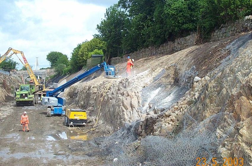
OUTLINE OF PRESENTATION

•   Overview of the LUAS Project and Project Team
•   Summary of the Geotechnical Works
•   Management of Geological / Geotechnical Risk
•   Case Study: Green Line – Kilmacud Cutting

                     www.jba.ie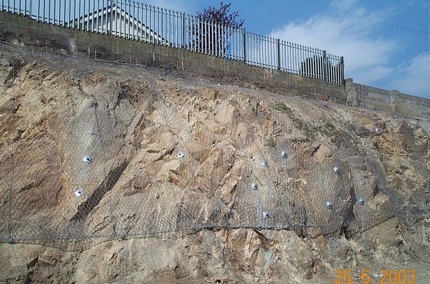
LUAS LIGHT RAIL SYSTEM : THE PROJECT

The LUAS system was planned, designed and constructed as
three separate lines :
(i)     Line A : Tallaght to O’Connell Street
(ii)    Line B : Sandyford to St. Stephens Green
(iii)   Line C : O’Connell Street to Connolly Station

Operated as two lines – Red Line (Lines A and C) and Green Line
(Line B). Opened in June 2004 and by June 2005 LUAS had
carried over 15 million passengers.

The Red Line runs at grade, partially along preserved transport
corridor, partially on existing streets. The Green Line runs mainly
along segregated alignment of former Harcourt Street railway line
                                www.jba.ie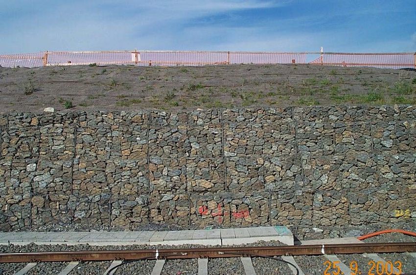
LUAS – DUBLIN LIGHT RAIL SYSTEM

        www.jba.ie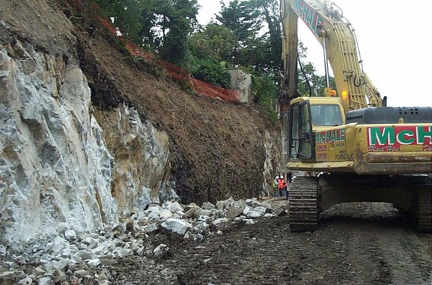
LUAS - THE PROJECT TEAM

Client : Railway Procurement Agency
Client’s Technical Advisor : Mott McDonald EPO

Design and Build Contractor : AMB – a joint venture between
           Ansaldobreda Transporti SpA (Italy)
           MVM Rail (Australia)
           Ballast Needam International (Netherlands)

Track and Civil Works Contractor : MVMBNI JV

Engineering Designer : Sinclair Knight Merz (SKM)
    Geotechnical Sub-consultant : John Barnett and Associates
    Drainage Sub-consultant : Roughan and O’Donovan

                        www.jba.ie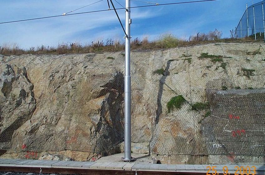
LUAS LIGHT RAIL SYSTEM : PRINICPAL ELEMENTS

•   23km of light rail track through built up urban environment
•   5 No. underground sub-stations
•   7 No. overground sub-stations
•   5 No. new bridge structures (3 footbridges, 1 rail, 1 cable)
•   Re-use of 4 No. existing masonry bridge structures
•   Re-use of 1.5km of masonry embankment retaining walls
•   Connolly Station Terminus
•   Control and Maintenance Depots (Red Cow and Sandyford)

• Not included in Track and Civil Works Contract :
                Dargan Bridge, Dundrum
                Red Cow Overbridge (M50)

                         www.jba.ie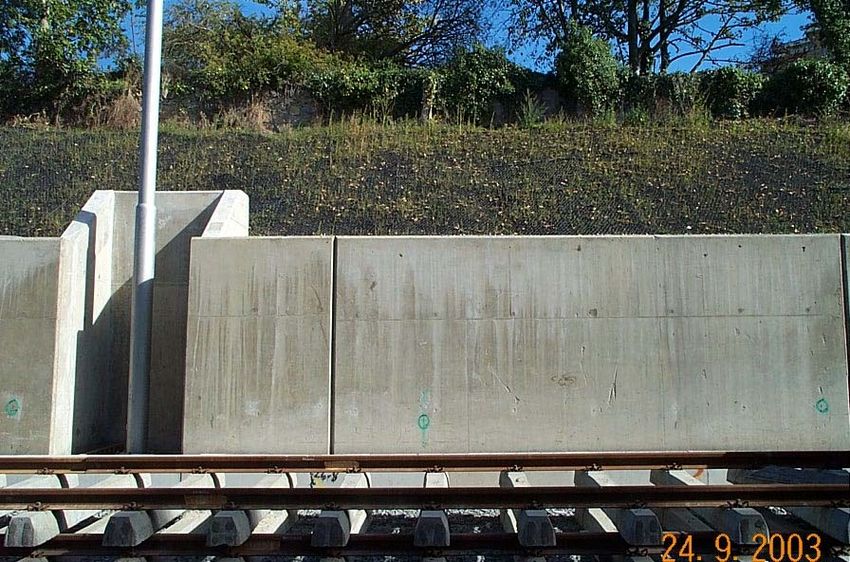
LUAS LIGHT RAIL SYSTEM : GEOTECHNICAL WORKS

• Track Foundation – 3 Track Types
• Underground Sub-stations: Cut & Cover Structures
• Re-use of Foundations for the Masonry Bridges along former
  Harcourt Street Line
• Selected Overground Structures : Sub-station Foundations
• Widening of the Kilmacud Cutting
• Depot Buildings: Foundations
• Park & Ride Facilities: Pavement Foundations

                        www.jba.ie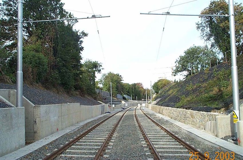
MANAGING GEOLOGICAL / GEOTECHNICAL RISK

The Employer’s Requirements called for the Design and Build
Contractor (AMB) to implement the UK Highways Agency
methodology for the planning, management and reporting of
geotechnical works as outlined in HD22/92
      ‘Ground Investigation and Earthworks Procedure for
      Geotechnical Certification’ (DMRB Section 4.1.1)

The following deliverables were required at key milestones in the
engineering design programme :
    Procedural Statement
    Preliminary Sources Study (Certificate No.1)
    Factual and Interpretative Geotechnical Report (Certificate No. 2)
    Earthworks Design (Certificate No. 3)
    Geotechnical Feedback Report
                       www.jba.ie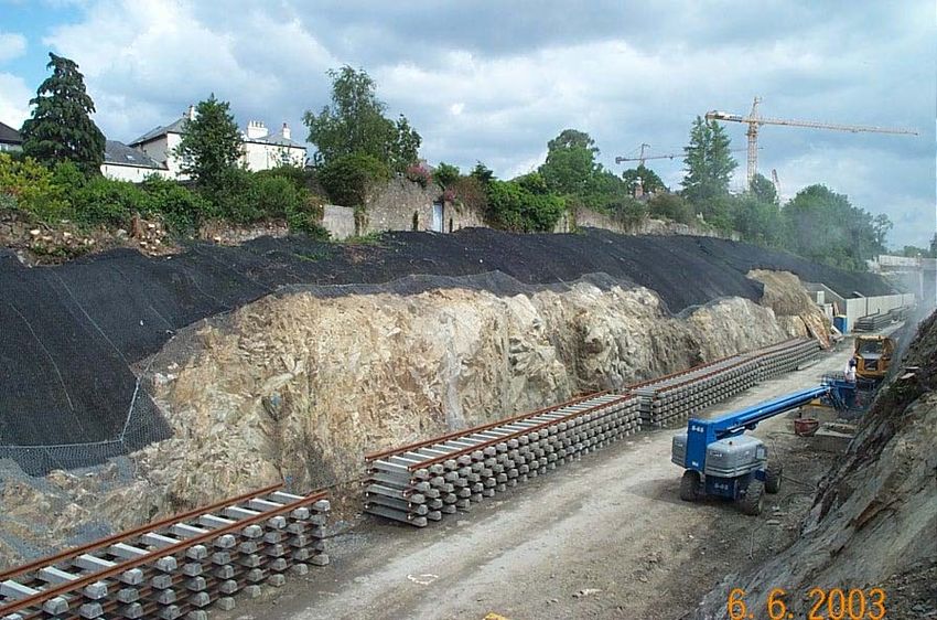
HD22/92 GEOTECHNICAL CERTIFICATION

    A Procedural Statement was prepared and submitted to the Client
    in advance of detailed engineering design.

    This is a statement of intent which briefly outlines what the designer
    proposes to do to satisfy the basic geotechnical requirements of the
    scheme. It includes the following : -

•   Description of the Light Rail Scheme
•   Statement of Geotechnical Design Philosophy / Objectives
•   List of Sources of Information to be Consulted
•   Details of Anticipated Ground / Groundwater Conditions
•   Programme for Desk Studies / Additional Ground Investigations
•   Outline of Report Formats

                              www.jba.ie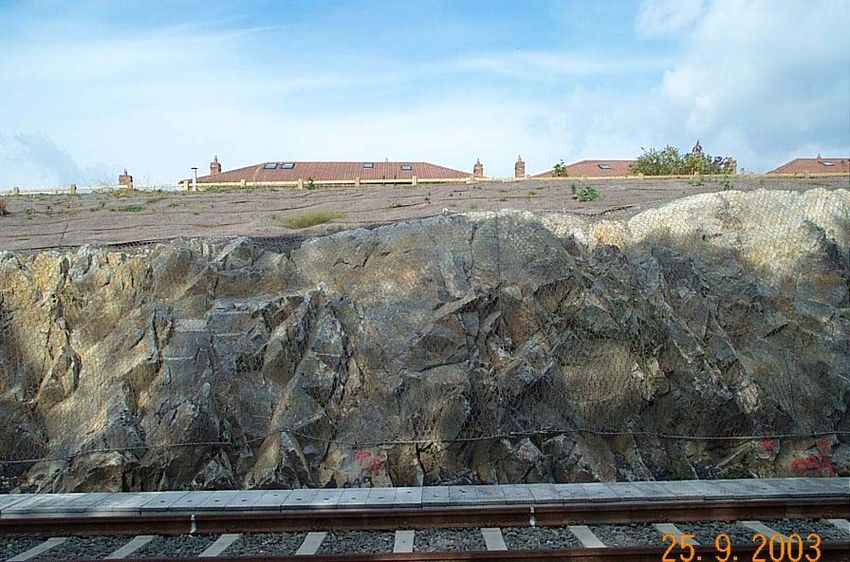
HD22/92 GEOTECHNICAL CERTIFICATION

Preliminary Sources Study (PSS) Reports were prepared in
respect of each ‘workfront’ section in accordance with the design
and construction programme.
    Red Line : Lines A and C – Workfronts A to F (6 No.)
    Green Line : Line B Workfronts K to P (6 No.)

The PSS Reports accompanied preliminary engineering design
submissions to the Client.
They were accompanied by Geotechnical Certificate 1,
confirming that the desk study element had been prepared with
professional skill and care in accordance with the Procedural
Statement.

                         www.jba.ie
HD22/92 : PRELIMINARY SOURCES STUDY
The Preliminary Sources Study Reports presented details of the
following :
• Published Regional Geology (Quarternary and Solid)
• Existing / Previous Land Use (Historic OS Maps)
• Previous Ground Investigations (largely sourced by RPA)
• Findings of Field Studies / Walkover Surveys
• Description of Ground and Groundwater Conditions
• Preliminary Engineering Assessment (based on available data)
• Detailed Proposals for Additional Ground Investigation
(scope, location, fieldwork and laboratory testing)
www.jba.ieADDITIONAL GROUND INVESTIGATIONS
Workfront PSS Reports identified a need for significant additional
ground investigation, over and above that provided at Tender Stage.
Additional GI generally done at start of construction phase along each
workfront as :
(i) much of site on heavily trafficked streets
(ii) much of site unavailable due to advance utility diversion contracts
(iii) much of former Harcourt Street to Bray line overgrown
(iv) no continuous access along elevated embankment (Harcourt St. Line)
As such, time available to complete the additional ground
investigation and prepare subsequent Factual and Interpretative
Geotechnical Reports was severely constrained.
www.jba.ieHD92/22 : GEOTECHNICAL REPORTS
Factual Geotechnical Reports presenting the findings of the
additional ground investigations were prepared by IGSL Ltd. for
track foundations and individual structures along each workfront.
Interpretative Geotechnical Reports were prepared by JBA for
individual workfronts and addressed all geotechnical design and
construction issues.
The Interpretative Reports were a further development of the
Preliminary Sources Study Report and accompanied detailed
design submissions to the Client.
www.jba.ieHD22/92 : GEOTECHNICAL REPORTS
Interpretative Geotechnical Reports for each workfront included
• Details of additional project-specific ground investigation
• Interpretation of ground profiles and groundwater regime
• Assessment of geotechnical design parameters
• Engineering design recommendations
The Interpretative Reports were ‘live’ documents, revised and
updated several times to take account of
• additional GI data acquired
• observations / experience gained during construction phase.
They were accompanied by Geotechnical Certificate 2,
confirming that geotechnical reporting had been undertaken with
professional skill and care.
www.jba.ieHD22/92 : GEOTECHNICAL REPORTS
Geotechnical Feedback Reports were prepared for each
workfront section by the Track & Civil Works Contractor (MVMBNI)
These reports include details of planning and execution of
geotechnical construction works, with particular emphasis on
problems encountered and solutions implemented. Particular
emphasis on
• Earthworks (materials, quantities, suitability criteria, instability)
• Pavement (subgrade preparation)
• Drainage (temporary / permanent)
• Structural foundations
• Materials Testing
• Instrumentation
www.jba.ieGREEN LINE (LINE B – WORKFRONT ‘N’)
KILMACUD CUTTING
• Introduction
• Typical Ground Profile & Groundwater Regime
• Slope Analysis: Parametric Study
• Cutting Design
• Slope Treatments
www.jba.ieLUAS LIGHT RAIL SYSTEM : KILMACUD CUTTING
www.jba.ieKILMACUD CUTTING : BACKGROUND
• Existing Cutting: Old Harcourt Street Line
• Cutting length: approximately 2 km
• Dundrum Station to the Kilmacud Footbridge
• Proposed use for LUAS light rail scheme and future Metro
required widening of the existing cutting.
• Interaction of a number of factors: Track width, OCS
system and poles, drainage and ducts, stations, ground /
groundwater conditions and localised historical instability.
www.jba.ieTRACK ALIGNMENT
• Constant track centres required for Metro operation:
3400mm
• This includes a dynamic kinematic envelope (DKE)
clearance allowance between each track of 400mm
• OCS poles located at side of track
• Track levels optimised (within constraints such as fixed
bridge locations etc.) to require to deepen the cutting
www.jba.ieGROUND PROFILE
• Programme of ground investigation (trial pits, boreholes,
groundwater standpipes and lab testing: strength)
• Typical ground profile comprises :
Topsoil
Made Ground
Glacial Till
Granite
• Groundwater: > 1 m below existing GL
www.jba.ieLOCALISED INFILLED CHANNELS IN GRANITE
www.jba.ieGLACIAL TILL : EFFECTIVE STRESS
STRENGTH PARAMETERS
• Programme of shear box tests
• Samples recovered from depths ranging from 1.0 to 3.5 metres
• Design parameters: c’ = 5kPa, Phi = 32 degrees.
www.jba.ieSLOPE ANALYSIS : PARAMETRIC STUDY
Parametric study undertaken to assess the maximum ‘safe’
height for slopes developed in Glacial Till.
• Shear Strength: c’=5kPa, Phi = 32 degrees
• Varying slope angles: 25, 35, 45 degrees
• Varying GWL’s: 1, 2 and 3 m below existing GL
• Target FoS (on soil Strength) = 1.3
www.jba.ieSLOPE ANALYSIS
Parameters: c’=5kPa, Phi = 32 degrees
GWL at 2 metres bGL
Maximum slope heights for FoS = 1.3
- 25 deg: > 6m
- 35 deg: 4.7m
- 45 deg: 3.8m
Note: Use of apparent cohesion, c’, is conditional on presence
of good quality vegetation and ongoing vegetation
maintenance.
www.jba.ieSLOPE ASSESSMENT
• Detailed topographic surveys
• Walkover inspection: existing slopes logged at 10m intervals
East and West sides of cutting
• Cutting Classification
• Methodology for Assessing Slope Treatment
www.jba.ieSLOPE INSPECTION www.jba.ie
CUTTING CLASSIFICATION

Rock Slopes :          1A

Rock / Soil Slopes :   2A (Soil < 26 deg.) to
                       2D (Soil > 45deg).

Soil Slopes :          3A (< 26 deg.) to 3D (> 45 deg.)

                       www.jba.ie
TREATMENT CLASSIFICATION
In order to optimise the cutting design and construction, within
the physical and programme constraints, a range of slope
treatments were designed.
Following the slope inspection and assessment an appropriate
slope treatment was selected and specified.
www.jba.ieSLOPE INSPECTION METHODOLOGY
www.jba.ieTYPES OF SLOPE TREATMENT
T3 : Soil slopes - Provision of vegetation and geogrids
(Where slope height exceeds design ‘safe’ height slope to
be re-graded or stabilised using retaining structure or soil
nails, e.g. T6)
T4 : Rock slopes - Rock bolts or support rock slope (plus rockfall
netting.
T5 : Soil / Rock slopes - Rockfall netting to rock slope and
vegetation / geogrids for glacial till.
T6 : Soil slopes - Cantilever insitu concrete retaining wall.
www.jba.ieRESTRICTED ACCESS TO CUTTING
www.jba.ieLRO BOUNDARY CONSTRAINTS
www.jba.ieTREATMENT T3 : REGRADE + BIOMAT
www.jba.ieTREATMENT T6 : RC WALL : CHAINAGE 16350
www.jba.ieTREATMENT T5 : ROCKFALL NETTING : CHAINAGE 17050
www.jba.ieTREATMENT T3 : GABION WALL : CHAINAGE 17400
www.jba.ieTREATMENT T4 : ROCK BOLTING AND ROCKFALL NET
www.jba.ieOCS RECESS : CHAINAGE 17300
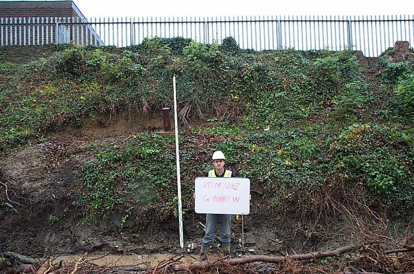
www.jba.ie‘AS CONSTRUCTED’ CUTTING - SITE RECORDS
www.jba.ieCOMPLETED CUTTING : CHAINAGE 17100
www.jba.ieCOMPLETED CUTTING : CHAINAGE 16900
www.jba.ieCOMPLETED TRACK : CHAINAGE 17700
www.jba.ieLUAS ‘GREEN’ LINE : KILMACUD CUTTING
SUCCESSFUL MANAGEMENT OF GEOLOGICAL /
GEOTECHNICAL RISK
www.jba.ieYou can also read