VLC SYSTEM USING PSOC MICROCONTROLLER
←
→
Page content transcription
If your browser does not render page correctly, please read the page content below
VLC System Using PSoC Microcontroller

     *
      Kalla Harish, **Prof. M.V. Lakshmaih, ***Prof. Pendem Suresh Kumar ,      ****
                                                                                     Prof. Thimmaih,
                                        *****
                                             J Avesh Gopal
                      *, **, ****
                                Srikrishna Devaraya University, Ananthapur, India.
                 ***, *****
                          Adama Science & Technology University, Adama, Ethiopia.
         Emails: anu.harishh@gmail.com, drmvl2009@gmail.com, pendemsuresh@gmail.com,
                           drptm2008@gmail.com, aveshgopal@gmail.com

Abstract:                                             diodes (LEDs) are flickered at visible speeds to
Present-day wireless communication has many           send information. Visible light communication
limitations like bandwidth depletion, security        does not have any possibility of leaking out
etc. Now-a-days the research on VLC (Visible          when the light is isolated, which offers better
Light Communications) system is offering new          security than wireless LAN, and does not suffer
possibilities in overcoming the problems              performance losses even when a variety of
associated with wireless communications               computers are connected at once. This
system. In the present study a model has been         technology is also notable because it uses eco
developed for addressing the above issues via         friendly IT green technology rather than
Visible Light Communications system for               electromagnetic waves, which can cause harm
power line communication through an 8-bit             to the human body [1].
PSoC microcontroller. The exclusive PLC chip          In addition, due to the decreasing prices of
CY8CPLC10, an 8-bit PSoC3 microcontroller,            LEDs and improvements in their light emitting
high intensity pi5 light emitting diodes (LEDs)       efficiency, LEDs are now used in special
and the LX1972 visible light sensor were used         lighting applications such as mobile device
for the transmitter and receiver. The analysis        displays, cars, traffic signs, and advertisement
done using software and hardware components           panels, as well as in the general lighting market,
have given voltage fluctuations were evaluated        such as current fluorescent lamps or
as a function of distance from 10-50cm and            incandescent lights. Specifically, the emitting
given good communication between two                  efficiency of the white LED has already
computers with minimum loss due to                    surpassed that of the fluorescent lamp, and more
deescalating.                                         outstanding products are appearing in the
                                                      current market. Recently, due to RF bandwidth
Keywords:      VLC       (Visible     Light           frequency depletion, confusion possibilities,
Communication), 8-bit PSoC3 microcontroller,          increasing security requirements, and super-
Power line communication, Visible light               speed ubiquitous communication environments,
communication.                                        radio frequency technology and mutually
                                                      complementary optical wireless communication
1. INTRODUCTION                                       technologies are being developed at a large
Visible light communications technology uses          number of companies and institutions
visible light (380-780nm) to deliver information      worldwide [2].
without the effects of electromagnetic waves,         When developing more complex projects, there
keeping      pace    with    current     wireless     is often a need for additional peripheral units,
communications. Lights of general fluorescent         such as operational and instrument amplifiers,
lamps or the visible light of light emitting          filters, timers, digital logic circuits, AD and DA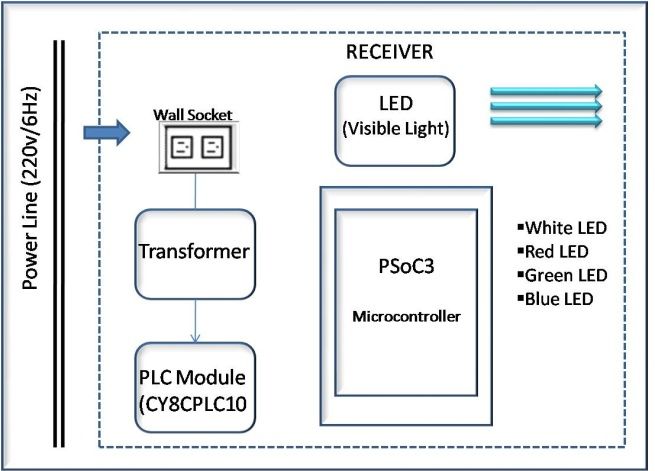
convertors, etc. As a general rule,                   integrating the CY8CPLC10 with a powerline
implementation of the extra peripherals brings        coupling circuit [3, 4].
in additional difficulties: new components take
space, require additional attention during
production of a printed circuit board, increase
power consumption. All of these factors can
significantly affect the price and development
cycle of the project. The introduction of PSoC
microcontrollers has made many engineers’
dream come true of having all their project
needs covered in one chip.
PSoC: Programmable System on Chip
PSoC represents a whole new concept in
microcontroller development. In addition to all
the standard elements of 8-bitmicrocontrollers,                   Fig. 1. System architecture.
PSoC chips feature digital and analog
programmable blocks, which themselves allow           2. EXPERIMENTS
implementation of large number of peripherals.        Visible light communication technology, which
PSOC3 element is inexpensive and provides the         has gotten notice as a next generation
PSOC Creator and it is highly flexible custom         communication technology, is particularly
microcontroller that allows the user to configure     attractive for home networks. Among the
the part for the current task at hand. In fact, the   technologies, the visible light communication
PSoC is considered to be a “blank slate” without      system is designed and brought into a network
any stock peripherals. Instead, the user must         using PLC to study application of the LED
specify which peripherals are required for the        system that is necessarily relevant for living.
project. The user may place any combination of        The visible light communication system based
available blocks to create the resources required.    on PLC uses a commercial alternating current
For instance, if the project requires 5 UARTS         electric power source 220 V/60 Hz power line
for serial communication, then the user can           and an RS-232C cable as a communication
place 5 UARTS inside the PSoC. This flexibility       medium, and consists of visible light
allows for extremely efficient designs but            communication parts including PLC receiving
requires significant upfront planning by the          and transmitting parts. The system developed in
user.                                                 this study transmits the input data from a
 This study will confirm the possibility of           computer to a PLC transmitter through an RS-
applying this technology for the next generation      232C port. This signal is converted into the
wireless network by creating a visible light          transistor-transistor logic (TTL) signal level
communication transmitter and receiver for            through DS276 chip, and is transmitted to the
power line communication (PLC) using an               PLC receiver through a power line cable after
PSOC. The CY8CPLC10 is designed for                   the data is transmitted to an exclusive PLC chip
systems that require a communication interface        through an 8-bit microcontroller. Data that is
over commercial high voltage (HV) or low              transmitted after these processes is received by
voltage (LV) powerlines. Typically, these             an exclusive PLC chip that is attached to the
systems consist of a microcontroller or               PLC receiver, and this signal passes through the
processor along with other electronic                 8-bit microcontroller and is transmitted to the
components that implement the host application        visible light communication light emitting parts.
functionality. The PLC interface is provided by       After the data is received from the visible light
receiving sensor through the LED of the visible 2.2 PLC receiver
light communication light emitting parts, the Figure 2 is the circuit image of the PLC receiver
lowered data signal is amplified by the OP-amp used in this study. The PLC receiver mainly
circuit, and the RS-232C cable is used through consists of the exclusive CY8CPLC10 PLC
the Microcontroller and the DS276 chip to send chip, microcontroller PSoC3 chip, and an
the data to other computers [7]. DS276 chip for the TTL signal level change.
The DS276 chip balances the voltage gap for the
serial communication between the PC and the
microcontroller. When data is transmitted using
the RS-232C cable in PC1, the data is
transmitted to the power line through the
exclusive PLC chip and the PSoC3
microcontroller.
2.3 PLC receiver and visible light
communication transmitter
This part of the system has a similar
composition to the PLC receiver, except that 3
of the 5pi LEDs are added to the light emitting
Fig. 2. Block diagram of the power line communication
(PLC) transmitter.
parts design. The signal that comes through the
power line is received through the exclusive
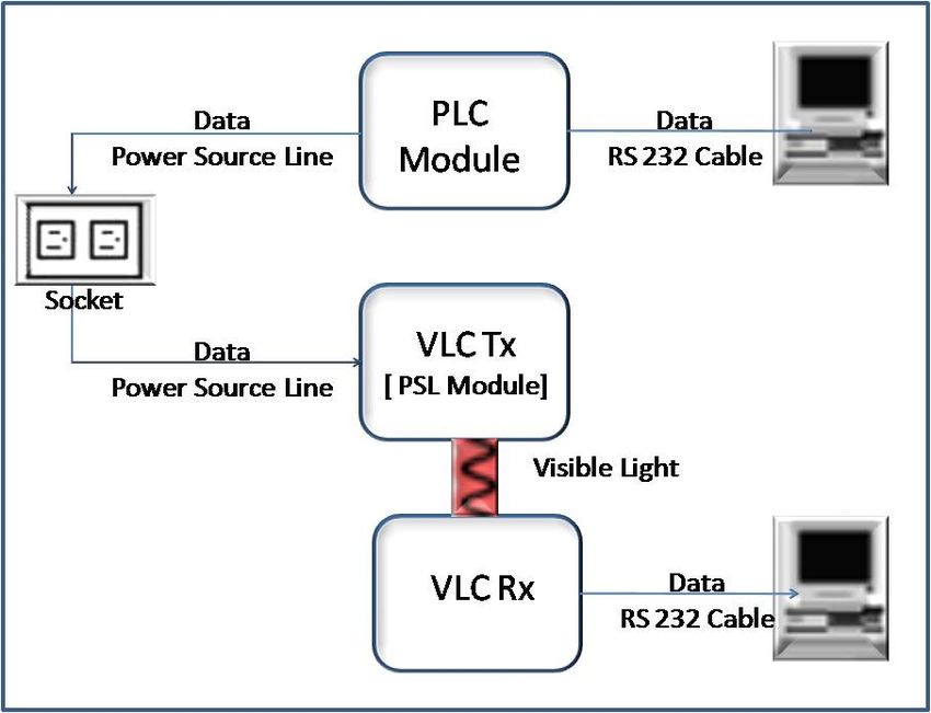
2.1 Composition of the system CY8CPLC10 PLC chip, and is transmitted to
The design in this study uses a commercial the LED through the PSoC3 microcontroller
alternating current electric power source, a 220 chip. Figure 3 shows the transmitter circuit
V/60 Hz power line as the communication image of the visible light communication
medium, and the system shown in Fig. 1 to system.
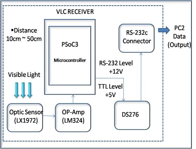
transmit the information. The distance between 2.4 Visible light communication receiver
the light emitting parts and the receiving parts of The composition of the visible light
the visible light communication should be communication receiver is different than that of
between 10-50 cm, and each LED should be the PLC transmitter or visible light
positioned horizontally. Each transmitting and communication receiver, as shown in Fig. 4.
receiving part has its own LED in order to The visible light communication receiver does
verify the information transmitting and not have an exclusive PLC chip, so it only has a
receiving process so that the conditions and visible light receiving sensor and PSoC3
power conditions can be checked in real time. microcontroller to receive the information. The
Real time checking of the transmitted and data is received in PC2 through PSoC3
received data is achieved by using the hyper microcontroller, which is an 8-bit
terminal window using Embedded C microcontroller, and OP-Amp LM324N after
programming. The visible light communication the data is received from the LED through the
data transmitting and receiving program uses LX1972 visible light receiving sensor [8,9].
letters so that the data transferred between
computers can be checked by eye. In this
manner, the performance of the processes can be
monitored and evaluated. In this process, the
transmitting and receiving port drivers of both
computers should be well connected in order to
communicate.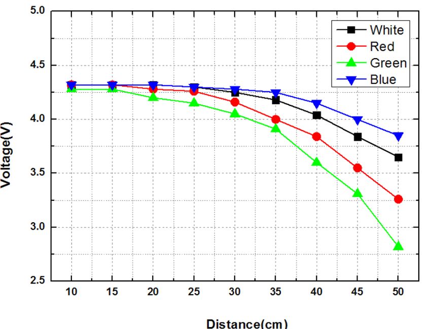
Fig. 3 Block diagram of the power line communication
(PLC) receiver and visible light communication Fig. 5. Voltage change value depending on light emitting
transmitter. diode color of communication distance.
In the case of the white LED, the voltage at a
distance from 10-35 cm was constant, but the
voltage for a distance over 35 cm showed a
dramatic voltage decrease. A voltage loss of
0.67 V was confirmed, with a voltage of 4.32 V
at 10 cm to a voltage of 3.65 V at 50 cm. Also,
in the case of the red LED, the voltage from 10-
30 cm was constant, but there was a dramatic
voltage decrease at distances over 30 cm. At a
distance of 50 cm, the voltage was 3.26 V, so
that 1.06 V was confirmed as the voltage loss.
The voltage loss of the green LED is 1.46 V,
Fig. 4. Block diagram of the visible light communication and the voltage loss of the blue LED is 0.47 V,
receiver. which shows the best performance among the
3. RESULTS AND DISCUSSION LEDs.
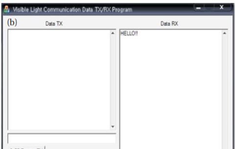
Figure 6 shows the process in which the letters Figure 8 shows the Visual C++ program that
are transmitted and received. The transmitter general users can easily take and adapt by
and receiver of the materialized system are adding letters to verify successful data
connected directly to the RS-232C port of the transmissions between the computers. In this
computer, and the output value is calculated, manner, "HELLO!!" was used as the input and
which is detected by the visible light receiving was transmitted to the other computer. The
sensor using an oscilloscope. The transmitting results were checked, and the blue LED showed
and receiving waveforms can be checked and the best performance when evaluated using an
verified as shown in Fig. 6. Figure 7 shows the oscilloscope.
values obtained from voltage change through
visible light receiving sensor from a voltage that
5 V is approved by distance using an
oscilloscope.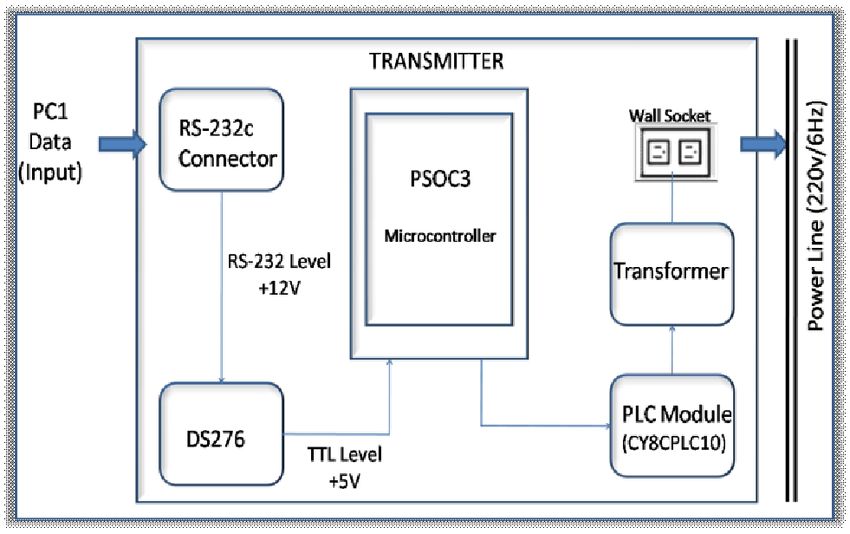
new issues were found by using the estimated
                                                        values.
                                                        In this study, the performance under changing
                                                        conditions was evaluated, and the efficiency of
                                                        the light emitting part and the receiving sensor
                                                        of the visible light were studied so that better
                                                        communication conditions can be achieved in
                                                        the future. Continuous study and improvement
                                                        are required. This study also confirmed the
                                                        possibility of applying this technology for the
                                                        next generation network.

Fig .6. Monitoring screen using program visible light   REFERENCES
communication data transmitter                          [1] T. G. Kang, K. H. Lee, D. H. Kim, and S. G.
                                                        Lim, KSII Trans. 10, 85 (2009).
                                                        [2] H. J. Kang, J. Digit. Contents Soc. 8, 425
                                                        (2007).
                                                        [3] Aditya Yadav, Designing an External Host
                                                        Application      for   Cypress’s      Powerline
                                                        Communication,                        AN55427,
                                                        http://www.cypress.com/?rID=38366
                                                        [4] Remote High Brightness LED Control Using
                                                        PowerPSoC and Powerline Communication
                                                        (PLC),AN60934,http://www.cypress.com/?rID=
                                                        37956
                                                        [5] J. M. Jung, J. M. Hwang, M. K. Kang, J. W.
                                                        Lee, and I. K. Kim, KSII Trans. 8, 557 (2007).
Fig. 7. Monitoring screen using program visible light   [6] D. W. Kim and S. W. Park, KIEE Trans. 55,
communication data receiver.                            161 (2006).
                                                        [7] T. Komine and M. Nakagawa, IEEE Trans.
4. CONCLUSION                                           Consum. Electron. 49, 71 (2003) [DOI:
In this study, a visible light communication            10.1109/TCE.2003.1205458].
system for PLC was created, and a simple                [8] S. Haruyama, IEICE Trans. Fund. Electron.
experiment was created to verify the system             Comm. Comput. Sci. 86A, 1284 (2003).
performance using a Embedded C program and              [9] T. Komine and M. Nakagawa, IEEE Trans.
an oscilloscope.                                        Consum. Electron.
The performance analysis was done by color at
communication distances from 10-50 cm with
5V, and showed that voltage loss can be
observed. As a result, the blue LED showed the
best performance at distances from 10-50 cm,
and there were no problems in the Embedded
program while the letters were transmitted and
received. As the distance increased, however,
the processing speed decreased due to the weak
signal treatment and the background lights,
which made it hard to receive precise data. Also,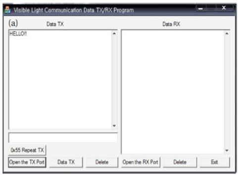
You can also read