2008 Saturn VUE Green Line Hybrid - Emergency Response Guide
←
→
Page content transcription
If your browser does not render page correctly, please read the page content below
2008 Saturn VUE Green Line Hybrid
   Emergency Response Guide

GM Service Technical College provides First Responder Guides (FRG) and Quick Reference (QR) Sheets free of charge to First Responders. FRGs
         and QRs can be displayed in a classroom as long as they are represented as GM information and are not modified in any way.
                                       GM’s First Responder Guides are available at www.gmstc.com

                                                                                                                                              1
Introduction
The intent of this guide is to provide
information to help you respond to
emergency situations involving the 2008
Saturn VUE Green Line Hybrid in as safe a
manner as possible.
While the majority of the components that
make up our hybrid are common to
traditional GM vehicles, there are some
differences that may affect how a rescue
procedure is performed.
There are similarities and differences
between the 2007 and 2008 Saturn VUE
Green Line Hybrid. We will point out those
similarities and differences as well.
This guide contains a general description of
how the 2008 Saturn VUE Green Line
Hybrid system operates, shows the location
of the badging, and offers illustrations of its
unique components. It also describes ways
of disabling the system and presents cut
zone information on the 2008 Saturn VUE
Green Line.

                                                  2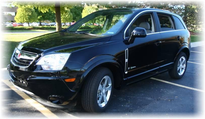
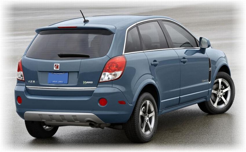
Vehicle Identification
Special badging is used on the
2008 Saturn VUE Green Line
Hybrid liftgate.
This badging is similar to the
badging used on the 2007
Saturn VUE Green Line Hybrid.

                                 3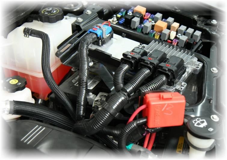
Vehicle Identification (cont.)
A hybrid badge is on the driver and
passenger front doors.
This badging is similar to the badging
used on the 2007 Saturn VUE Green
Line Hybrid.

                                         4
Vehicle Identification (cont.)
A tachometer with Auto Stop indicator
and a Charge/Assist gauge are unique to
the 2008 Saturn VUE Green Line Hybrid.

                                Tachometer with
                                Auto Stop
                                Indicator and
                                Charge/Assist
                                Gauge

                                                  5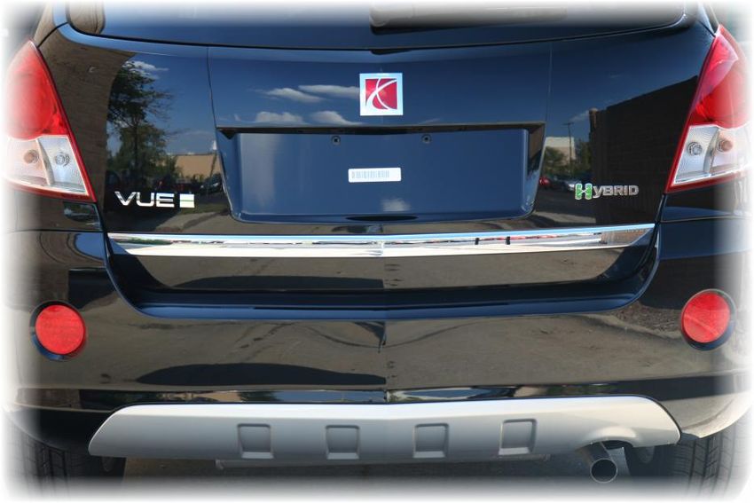
Vehicle Identification (cont.)
Under the hood is:
    •   A hybrid badge on the engine cover
    •   A label showing the battery locations
        (attached to the core support)

                                                6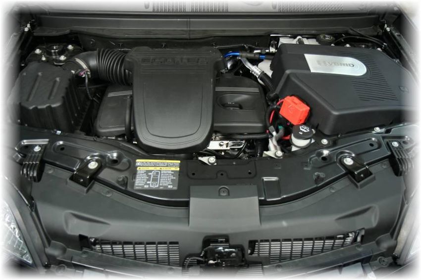
Vehicle Identification (cont.)
Under the rear cargo floor is a label showing the battery
locations (attached to the hybrid battery case).

                                                            7
Vehicle Identification (cont.)
Comparison of 2007 and 2008 Saturn VUE Green Line Hybrids

   2007 VUE Green Line Hybrid                               2008 VUE Green Line Hybrid

                                                                                         8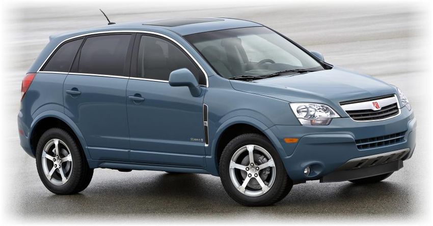
System Operation
The 2008 Saturn VUE Green Line Hybrid is a
gasoline-electric hybrid vehicle that uses up to 27
percent less fuel than the non-hybrid 2008
Saturn VUE.

The 2008 Saturn VUE Green Line uses a 36 volt
electrical system coupled with a traditional 12
volt battery and sophisticated technology to
achieve its fuel savings.

The vehicle is equipped with a 2.4 liter, 4-cylinder
engine and a traditional 12 volt starter motor,
which is used only for initial starts of the vehicle.

                                                        9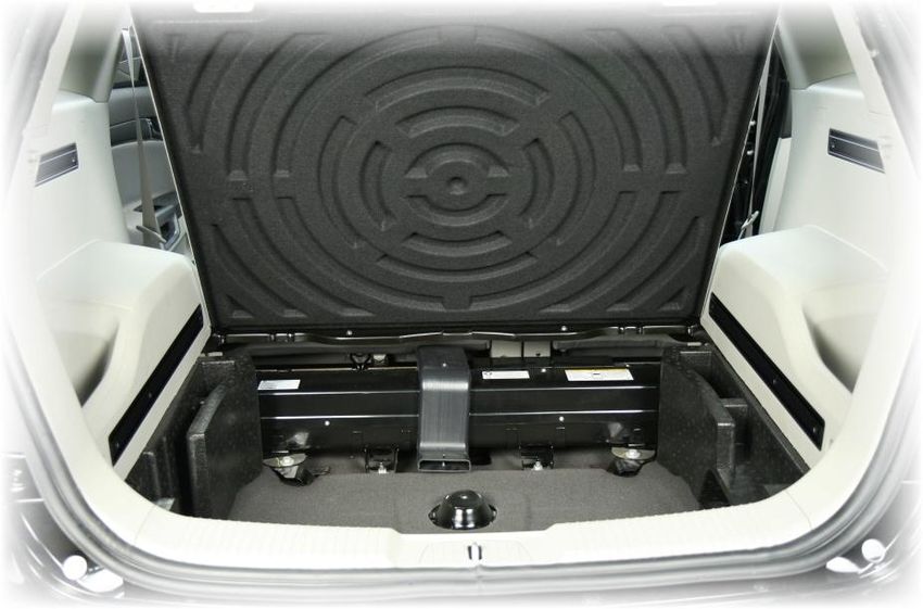
System Operation (cont.)
During braking and deceleration, energy is recovered
and stored in the hybrid battery (also known as the
generator battery). The engine‘s fuel supply is
interrupted and the engine temporarily shuts off as the
vehicle comes to a full stop. This is referred to as Auto
Stop.

There are conditions when the engine will be restarted
by a special starter generator. Some of these
conditions include:
    •   The gear shift lever is moved from Drive to
        another gear
    •   The hybrid battery charge is low and requires
        recharging
    •   Auto Stop has timed out (maximum of 120
        seconds)
    •   Normal A/C mode is selected
    •   Full front Defrost mode is selected
    •   The accelerator pedal is applied
    •   The brake pedal is released
NOTE: The starter generator cannot provide sustained
vehicle propulsion by itself. It is primarily used for
starting the engine after an autostop and for engine
assist during accelerations.

                                                            10
System Operation (cont.)
Auto Stop will not shut down the engine if any of the following
conditions apply:
• Engine is not warmed up
• Outside temperature is 95 F (35 C) or higher
• Shift lever is in any gear except Drive
• Hybrid battery charge is low
• 12volt vehicle battery charge is low, or charge
requirements are high
• Hood is not fully closed
11System Operation (cont.)
Several factors affect how long the engine remains off during Auto Stop:
• Outside temperature (95 F (35 C) or above decreases the time
the engine remains off)
• Air Conditioning setting (A/C is affected by outside temperature
when green Economy light is illuminated)
• Time limit
Hybrid
A/C Button
12DC/AC Voltage Classifications
Electricity is categorized as either low,
intermediate, or high voltage.
Low
• Low voltage – from 0 to 30 Classification Intermediate Voltage High Voltage
Voltage
volts DC / 0 to 15 volts AC
Voltage DC ≤ 30v DC > 30 ≤ 60v DC > 60v
• Intermediate voltage – from Ranges — — —
30 volts or greater to 60 volts AC ≤ 15v AC > 15 ≤ 30v RMS AC > 30v RMS
DC / 15 volts or greater to 30
Vehicle Conventional 2008 Saturn VUE Green Two-mode Hybrid
volts AC Line Hybrid
Application
• High voltage – any voltage ** GMC Sierra/Chevrolet
* GMC Sierra/Chevrolet Silverado Parallel Hybrid
greater than 60 volts DC / 30
Silverado Parallel Hybrid Trucks
volts AC Trucks
Color coding is used to identify the
different levels – blue for intermediate * Applicable to 36v DC Hybrid Battery Pack, 36v DC Power Steering System and 36v DC
voltage and orange for high voltage. Starter Generator Control Module (input)
** Applicable to Starter Generator Control Module (inverted APO output) and 120v AC
The 2008 Saturn VUE Green Line Accessory Power Outlets (APO)
Hybrid falls within the intermediate
range.
Two-mode hybrids and GM‘s Silverado Note: Presently there are no industry standards to identify intermediate voltage.
and Sierra Parallel Hybrid Trucks are a GM has chosen BLUE for the cable color.
combination of intermediate and high
voltage systems (see chart footnote).
13DC Voltage Classifications (cont.)
Even though the 2008 Saturn VUE Green Line Hybrid uses lower
voltage than other hybrids you may encounter, it must still be
approached with caution.
14Key Hybrid Components
This illustration shows the location of the hybrid components.
Hybrid Battery
36v Wire Routing Disconnect
Unit with
Disconnect Switch
for 36v Battery
36v Hybrid Battery
Starter
Generator
Generator 12v Battery
Control (not shown)
Module
15Key Hybrid Components (cont.)
The 2008 Saturn VUE Green Line Hybrid uses a conventional
internal combustion engine coupled with an electric machine
that serves as a generator, a starter and a motor to efficiently
power the vehicle.
Note: All intermediate voltage cables used on the hybrid model
are colored blue for easy identification.
Conventional Engine
with a Starter Generator
16Key Hybrid Components (cont.)
A 3-phase starter generator, capable of generating more
than 5000 Watts of electrical power, starts the engine when
the vehicle is in the Auto Stop mode. The unit is mounted
on the right side of the engine and replaces the standard
generator used on non-hybrid models.
Intermediate voltage cables are routed through the back of
the starter generator. The cables carry 36-42 volts of
electricity.
Always use caution when you are near these cables until
you are sure the hybrid electrical system is disabled!
Starter Generator
17Key Hybrid Components (cont.)
The starter generator control module, which is mounted on the left
side of the engine, manages the routing of the 36 volt electrical
system.
A 36 volt cable from the hybrid battery and three 36 volt cables
from the generator with starter enter the module at the top of the
component. A protective plate covers the cables.
Two coolant hoses, attached to the back of the module, connect
the starter generator control module with the engine‘s cooling
system. These hoses may contain hot coolant that could scald if
they are disconnected or cut.
Note that blue wiring is used to indicate intermediate voltage.
Cables from the starter generator, 12v
battery and 36v battery enter the side and
bottom of the starter generator control
module (cover removed for clarity)
WARNING: Hoses may
contain hot coolant that
could scald if they are
disconnected or cut.
18Key Hybrid Components (cont.)
A Nickel Metal Hydride (NiMH) 36 volt hybrid battery is enclosed
in a metal case located beneath the rear cargo floor.
19A 10 mm hex head nut
Key Hybrid Components (cont.) secures the Hybrid Battery
A separate box, called the hybrid battery disconnect Disconnect Unit cover
unit, is attached to the hybrid battery case.
Within the box are the negative and positive battery
cables for the hybrid battery. Opening the hinged
cover causes a spring-loaded disconnect switch to
interrupt electrical flow from the hybrid battery to the
starter generator control module.
Hinges hold the
cover in place
Disconnect Switch
(shown with Hybrid Battery
Disconnect Unit cover open)
20Key Hybrid Components (cont.)
Transmission Control
A 12 volt battery provides power for the vehicle‘s
Module (TCM)
accessories such as the radio, HVAC, and lighting. It is Engine Control Module (ECM)
also used during the initial start-up of the vehicle.
Two negative (-) cables attach to the negative (-) battery
terminal.
Note that the 12 volt battery is located beneath the Engine
Control Module (ECM) and Transmission Control Module
(TCM) bracket in the engine compartment. The photo on
the right is shown with Hybrid engine cover removed.
The 12v Battery is
located beneath the ECM
(actual battery has two
negative (-) cables)
21Key Hybrid Components (cont.)
A hood ajar switch is mounted near the hood latch and prevents Auto Stop from functioning if the hood of the vehicle is open.
If the hood is opened while the vehicle is in Auto Stop, the tachometer will move to the OFF position and the engine will be
disabled from restarting unless the ignition key is used.
Note the hood ajar switch will not prevent current flow through the 36 volt electrical system.
22Airbag Deployment
A contactor inside the hybrid battery is
designed to open if one or more air
bags deploy. This will cause current
flow in the 36 volt cable to be reduced
to a low level.
After air bag deployment, wait for at
least 10 seconds to elapse to allow any
undeployed air bag reserve energy to
dissipate.
In an instance in which one or more air
bags remains undeployed, disabling 12
volt power is essential to ensure
personal safety.
WARNING: WAIT a minimum of 10
seconds to allow the undeployed
airbag reserve energy to dissipate.
231. Turn the ignition key to the OFF position (if possible)
Disabling 12 Volt Power
Perform ALL of the following 4 steps WARNING: WAIT a minimum of 10
to disable the 12 volt electrical seconds to allow the undeployed
system. This includes power to the airbag reserve energy to dissipate.
airbag system. After removing the
Hybrid engine cover do the following:
2. Disconnect or Cut both negative (-) battery cables
1. Turn the ignition key to
the OFF position (if
possible)
2. Disconnect or Cut both
negative (-) battery
cables
Front of
Vehicle
3. Disconnect or Cut the
red cable attached to Cut here to disable BOTH 12v
the underhood fuse negative cables at the same
block time
4. Verify tachometer
needle is
pointing to OFF
3. Disconnect or Cut the red cable 4. Verify tachometer needle is pointing to OFF
WAIT a minimum of 10 seconds to attached to the underhood fuse block
allow any undeployed airbag reserve
energy to dissipate.
Note: Since one of the 12v negative (-)
cables is partially hidden from view, it
is best to disconnect the cables from
the terminal or cut the cables near the Cut here to disable engine if
terminal as shown at right. ignition key is not accessible
2436 Volt Electrical System
Do NOT cut the blue intermediate
voltage (36v) cable, because there is a
higher arc potential.
First perform the ―Disabling 12 Volt
Power‖ procedure on the previous page
to eliminate current flow on the 12 volt
electrical system. This also reduces the
36 volt current flow to a low level in the
blue intermediate voltage (36v) cable.
No further action is required.
CAUTION: Cutting the blue cable may
result in an arc hazard.
CAUTION: Cutting the blue
cable may result in an arc
hazard.
25Do Not Cut Zones DO NOT CUT HERE. Roof rails may
CAUTION: DO NOT cut the vehicle contain side impact air bag
until all of the electrical systems have inflator canisters
been deactivated and isolated. Cutting
into the vehicle prior to disconnecting
and isolating the electrical energy
sources may cause an electrical arc
and/or personal injury.
Do not cut the:
• Center of the vehicle.
Intermediate 36 volt wiring is
routed in a channel beneath
the vehicle.
• Roof rails between the
windshield and ‗D‘ pillars
(rear pillars).
• Hybrid battery. The hybrid
battery has 36 volt electrical DO NOT CUT HERE. Hybrid
potential at all times. Battery has 36v electrical
• Blue conduit located in the potential at all times.
engine compartment.
Intermediate 36 volt wiring is
routed in a channel beneath
the vehicle.
DO NOT CUT HERE. Blue
DO NOT CUT HERE. Blue anodized conduit beneath the
conduit in engine compartment vehicle contains intermediate
contains intermediate 36v 36v electrical wires
electrical wires
26Conclusion
We are serious about making your job
as safe as possible.
As you have seen, certain differences
exist between the 2008 Saturn VUE
Green Line Hybrid and conventional
vehicles. These differences require
forethought when approaching an
emergency situation concerning a
Saturn hybrid.
We are confident the information
contained in this guide will prove useful
as you prepare to assist those involved
in the event.
For information regarding modification of
GM‘s First Responder Information for
other uses, contact GM‘s Licensing
Manager at:
GM Licensing Program Headquarters
5775 Enterprise Ct
Warren, MI 48092
Attn: Licensing Coordinator
© Copyright 2006, General Motors Corporation
27You can also read