Duke Energy s DA (Distribution Automation) Program - Rod Hallman - Sr. Engineer New Technology Group - Product specifications, product selection ...
←
→
Page content transcription
If your browser does not render page correctly, please read the page content below
Duke Energy‟s DA (Distribution Automation) Program
    Rod Hallman – Sr. Engineer
    New Technology Group – Product specifications, product selection, testing, deployment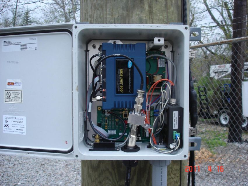
Disclaimer: This presentation covers and touches on all
aspects of smartgrid deployment and is not specific to just
substations (inside the fence).

Also, this presentation is covering what is being deployed in
Ohio only. Other states are deploying pieces of this plan in a
similar manner in other states that are not covered under a
true “Smartgrid” plan.
Overview of Duke Energy 5 states: North Carolina, South Carolina, Indiana, Ohio and Kentucky 50,000 square miles of service area 35,400 MW of owned generating capacity 4.0 million retail electric customers 500,000 retail gas customers 18,600 Employees Revenue $12.7 Billion
Duke Energy Smart Grid
On December 31, 2008, the Ohio utilities commission approved a recoverable Smart Grid plan aimed at
using new technology to transform our system into an advanced distribution system capable of remote
operation and data acquisition for multiple purposes.

This is a 5 year plan, being implemented through 2013.

So what’s included?

Smart Grid has two parts: Advanced Metering Infrastructure (AMI) and Distribution Automation.

Advanced Metering Infrastructure (AMI) includes retrofitting or replacing about 800,000 electric meters and
500,000 gas meters with meters that have two way communication and remote control capabilities.

Benefits include:
•Remote meter reading
•Remote connect / disconnect
•Accurate load information for better circuit modeling and enhanced transformer loading.
•Enhanced PQ from high/low voltage reporting
•Leverage internal breakers for load shedding, if needed.
•May allows customers flexibility on usage and rates. TOU for example.
•Outage detection
Back to our servers

                     Power line carrier (PLC)
Communication Node

                                            Cellular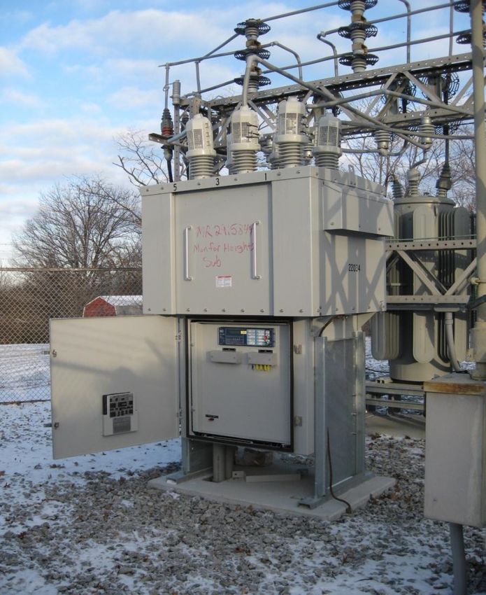
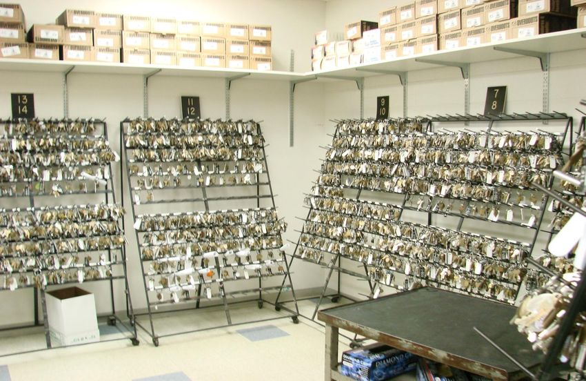
Ohio Key Room

                6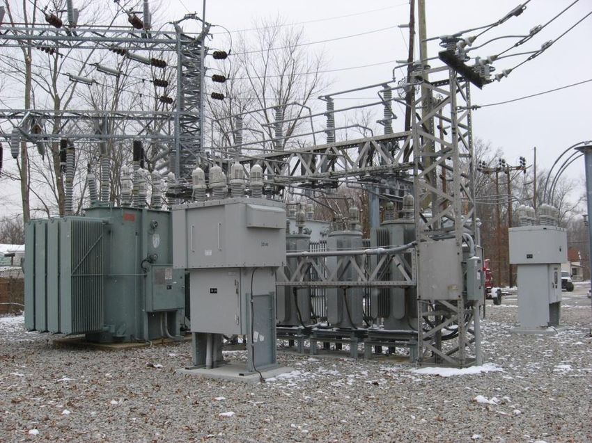
Meter Reading / Routine Order Challenges There are approximately 60,000 customer premise keys maintained for the greater Cincinnati area. (Behind locked fences, in buildings, etc) These keys are used for meter reading and routine order fulfillment (connects, disconnects, re-reads). Many customers refuse to allow Duke Energy Ohio to maintain keys to their homes & businesses resulting in: 8% of all bills being estimated Equates to over 1.1 million estimated bills annually Requires numerous customer appointments for routine order fulfillment

Distribution Automation Components

Substation                  Distribution Lines
•Circuit Breakers           •Sectionalization
•Relaying                   •Elect. Recloser Comm.
•Voltage Regulators\LTC‟s   •Capacitor Controls
•Communications             •Self Healing
                            •Line Sensors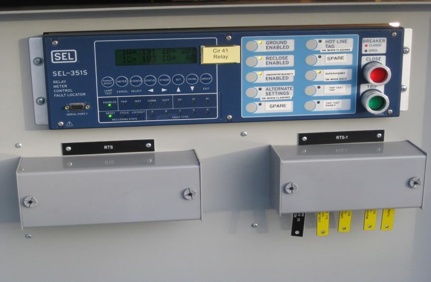
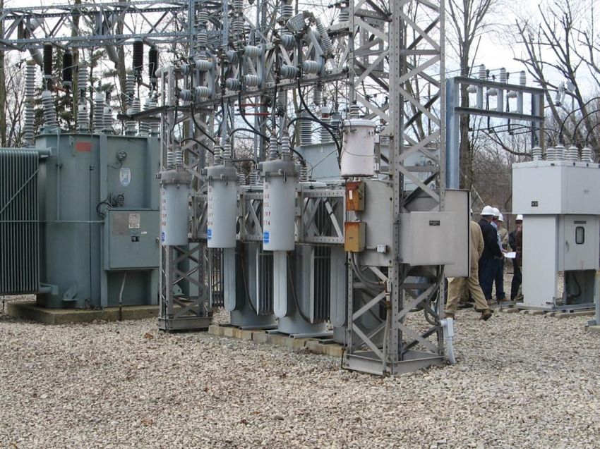
Substation Components
Substation Communications & RTUs

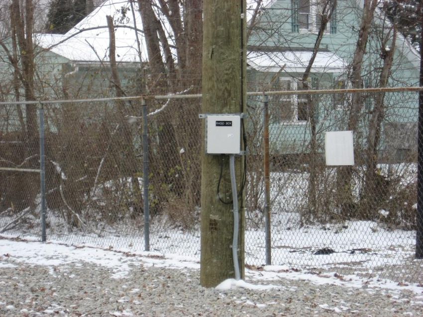
•Installing communications where none exists and installing or
 upgrading Remote Terminal Units (RTU‟s) to establish a
 communication gateway or “pipe” into and out of the
 substation, thus enabling advanced DA by using Duke owned
 Fiber, IDEN Radio, 900Mhz Radio or Leased Telephone Line.

•Substation communications include about 50% leased line,
 35% IDEN (900Mhz) and 15% Fiber. Note: Carolinas use
 cellular for control in most substations.
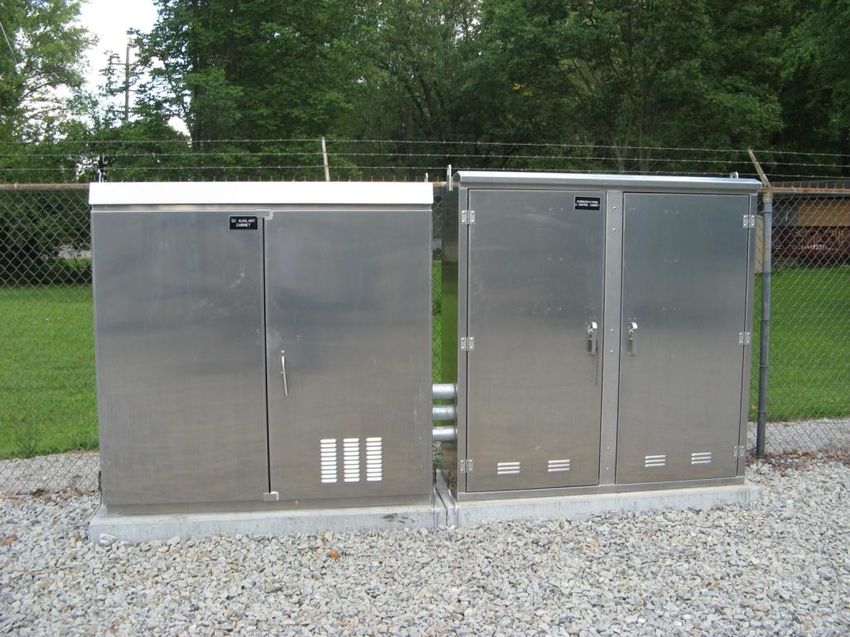
DC & RTU Communication Cabinets
Serves as communication „pipe‟ and „gateway‟ into substation, using Duke owned Fiber, Cellular, IDEN Radio, 900
Mhz Radio or Leased Telephone Line

Left DC Cabinet                                          DC Cabinet
DC & RTU Communication Cabinets
Right RTU Communication Cabinet   RTU Communication Cabinet
Communications to Substations/ RTUs
Again, communications to our substations may include leased lines, private radio (900 Mhz IDEN), or
fiber
Example of the use of our 900 Mhz radio system
                                                       Antenna on 100‟ Pole
900 Mhz Radio Cabinet
Communications to Substations/RTUs
900 Mhz Radio CabinetCircuit Breakers Replace existing reclosers with vacuum circuit breakers and microprocessor based relays. Applies to approx 15% of breakers. •Allows remote operation of breakers and remote data acquisition. •Allows circuit breakers to become part of self healing networks when needed. •Accurate real time data for circuit modeling, via Distribution Management System (DMS) system. •Approximate distance to fault source.
Replacing Reclosers with Vacuum Circuit Breakers
Old Reclosers                       New Circuit Breaker

                Applies to approximately 15% of breakers
Circuit Breakers with Relays Allows remote operation of breakers (open, close, block, un-block, e-tag) and remote data acquisition (status, loading, fault current, voltage, PF, relay settings, part of Self Healing Teams)
Microprocessor based Relays
Replacing old technology, electro-mechanical relays with
microprocessor based relays.

•Allows remote operation of breakers and remote data
 acquisition.
•Allows circuit breakers to become part of self healing
 networks when needed.
•Accurate real time data for circuit modeling, via
 Distribution Management System (DMS) system.
•Approximate distance to fault source.
Microprocessor Based Relay
Allows remote operation of breakers (open, close, block, un-block, e-tag) and remote data acquisition
(status, loading, fault current, voltage, PF, relay settings) Enable Self Healing (as needed), Accurate
real time data for circuit modeling, Approximate distance to fault source
Microprocessor Based Relay
                               New Digital Microprocessor Based Relay
                               (mounted on new plate on the existing
Old Electromechanical Relays   door)
Digital Microprocessor Based Relay
Old Electromechanical Relays New Digital Microprocessor Based Relay
(mounted on new plate on the existing door)Voltage Regulators/LTC Controls •Replacing voltage regulator and load tap changer (LTC) controls and installing communications. This will allow station regulators and LTC‟s to be part of our future integrated Volt/VAR control system and will provide remote diagnostics. •Replacing older voltage regulators that are not conducive (won‟t accept a newer control) to automation.
Quick Explanation of Integrated Volt-Var Control (IVVC)
• Today all capacitors and regulators operate independently based on what they see
  locally.
• The idea is to have a centralized controller that takes data from all regulators and
  capacitors and then operates them as needed in an effort to improve power factor
  and reduce line losses.
• We also want to use this controller to reduce energy demand through voltage
  reduction (flatten the voltage as much as possible and lower to circuit voltage a
  percent or two, thus lowering energy demand). It has not been determined if this
  would be implemented only during summer/winter system peaking conditions or
  24/7/365. Industry information and our experience has shown that a 1% reduction
  in voltage results in a .7% reduction in energy consumption.
• Upgrading controls that allow communications and remote operations will allow us
  to implement our long term vision of an Integrated Volt\Var Control system (IVVC)
  to be installed on all circuits.
Voltage Regulators/LTC Controls
Replace voltage regulator and load tap changer controls and install communications. This will enable
integrated Volt/VAR control and remote diagnostics. The implementation of integrated volt-var control
will increase line efficiency and potentially lower energy consumption.
   Old VR Control                                  New VR Control (mounted in existing cabinet)
Voltage Regulators/LTC Controls
 Old VR Control            New VR Control (mounted in existing cabinet)
Voltage Regulators/LTC Controls
Old LTC Controls          New LTC Controls (mounted on existing door)
Voltage Regulators/LTC Controls

 Old LTC Controls         New LTC Controls (mounted on existing door)
Distribution Line Components
Sectionalization – installation of strategically placed sectionalization devices to limit the number of
customers out for permanent faults. This will be achieved mostly with hydraulic reclosers. There are
some electronic reclosers. Not exactly new technology, but reliability benefits are huge. Installing
450 reclosers (hydraulic and electronic)
                                                                      Electronic Reclosers

                Hydraulic Reclosers
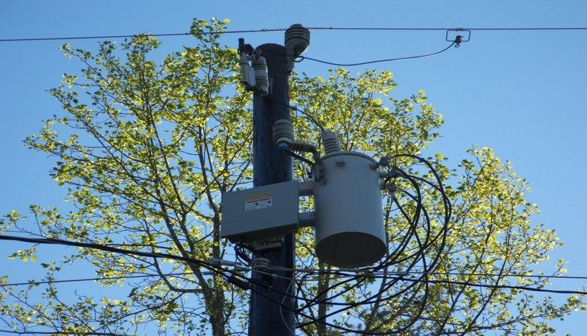
Capacitor Bank Controls Existing capacitor bank controls will be upgraded to accommodate communications via digital cell to allow for remote diagnostics and enable integrated Volt/VAR control. • Again, establishing communications to regulators and capacitor controls will allow us to implement our long term vision of an Integrated Volt\Var Control system (IVVC). • Another benefit of communication to capacitors is for detection of blown cap fuses through neutral current alarming. This has been in place in Carolinas for about 4 years.
Automated Capacitor Bank Controls
 Enables (IVVC) integrated volt / VAR control, energy efficiency and reduces demand / generation
need via Voltage Reduction Strategy, remote diagnostics (high / low voltage)
Adding Communications to Existing Electronic Reclosers
Allows remote operation of Electronic Reclosers (open, close, block, un-block, e-tag), remote data
acquisition (status, loading, fault current, voltage, PF). Adding communication to 130 existing
Electronic Reclosers.
                                       Cell Modem Antenna
Self Healing – Install self healing on 8% of our circuits in Ohio. The
obvious goal is to reduce the number of customers experiencing outages
for permanent faults. Installing 30 networks.
Self healing is adding intelligence such that faults or a loss of
voltage is automatically detected, isolated and power is
restored to all other line segments.
Example – 2 Circuits with Open Point in Middle
Automatic Automatic
Substation 1 Devices Device Substation 2
X X X
Circuit
Breaker 1 Automatic Device Circuit
at Open Point Breaker 2
Next
Circuit Breaker Device at Open
Downstream
Locks Out Point Closes
Device OpensCentralized Architecture for Duke
Elec Recloser
Brand X, Y & Z
AREVA\SCADA Elec Recloser
DA Controller
Elec Recloser
DA Controller from brand X, Y or Z could be attached to our existing SCADA system (AREVA) and
provide control through AREVA based on data coming into AREVA. Communcations would be
provided via cellular, IDEN, 900 MHz or other.Centralized Architecture Cooper ER
DA Controller/Server with
Self Healing Software
SCADA
ABB ER
Control Room
Operator
All data comes into our SCADA system, then into the DA Controller, via cell modem.
When needed, the DA Controller will issue control commands to isolate the fault and restore power to the
unfaulted areas. Operator can disable or enable automation through the SCADA.Permanent Fault Example – An upstream protective device will operate to lockout first. Once lockout has
occurred, the system says “who saw the fault?”. Once this is determined, the devices on all sides of the
fault will open, then power will be restored to the unfaulted sections of line.
Click on picture to start videoLine Sensors – installation of sensors along the distribution line to provide immediate outage
detection, fault locating assistance, along with load monitoring. Current projections are to install
about 3000 units, mostly at major load splits and behind hydraulic reclosers.
Sensor A - Provides outage indication, fault indication and load data with
communication via an internal cell modem.
Sensor B - Provides outage indication, fault indication and load information with
communication via wifi to an ambient node.Cellular
DOMS
Centrally
SCADA Located
DMS Server
PI
Hist.WIFI
Cellular
DOMS
Centrally
DMS SCADA Located
Server
PI
HistorianSmartgrid Automation Field Infrastructure with Communications
Cap. Elec. Elec. Elec. Cap.
Station Bank Recloser Line Reg Recloser Line Reg Recloser Bank Station
Line Sensor Line
Sensor
Self Healing SCADA
8%
Control Room
IVVC Operator
All Circuits
Distribution
DMS to provide real time circuit Management Outage
modeling for overload alarming, System (DMS) Management
load analysis, provide post outage System (OMS)
switching recommendations and
fault locating assitance among
many other features.Time For Questions
You can also read


