Performance Specification for Eco-Park Car Park Ventilation Systems
←
→
Page content transcription
If your browser does not render page correctly, please read the page content below
Car Park Ventilation Systems

Performance Specification for Eco-Park®
      Car Park Ventilation Systems
1
INDEX

1) Introduction

2) System Works

3) Design Criteria

4) System Description

5) System Components

6) Fan Ratings

7) Cabling Specification

8) Design CFD and Velocity Profile Diagrams

9) Testing , Commissioning and Documentation

                                               1
Eco Park® Sustainable Car Park Ventilation Systems
1 INTRODUCTION / PERFORMANCE OBJECTIVES
Provide, guarantee and warrant a car park ventilation of the Induction type to serve all levels of the car park in
accordance with BS 7346-67 and to satisfy Building Regulations Approved Document B and F.
The approved contractor will install a mechanical ventilation system to control the levels of petrol vapour, toxic gases and
smoke within the car park by the provision of a low profile induction fan thrust system. The system will be designed in
accordance with the guide lines of BS 7346-7
2 SYSTEM WORKS
The specialist shall design supply, install, coordinate with other contractors, test, and commission and set to work a
complete mechanical extract ventilations system to serve the basement car park area. This includes the supply ,
installation cabling connection and commissioning the main extract fans and silencers , Induction thrust fans motorised
dampers wiring , controls, CO monitoring , smoke detection and interface wiring to 3rd party fire alarm via volt free
contacts.
The car park ventilation system shall be of the induction type selected to meet the needs of the car park and ramps
taking into account the Design Fire size as required by BS 7346-7 – 2006 or independent strategy all backed by the
necessary smoke pattern calculations :
The system design shall determine air volumes, temperature within the space, operation duration, toxicity levels, air
movement strategy and power supply/control requirements in accordance with Building Control and Local Fire Officer’s
requirements and in accordance with BS 7346-6. The performance of the complete scheme will be guaranteed and
warranted by the system supplier and installer.
3 DESIGN CRITERIA
Provide minimum extract air from the car park in the following proportions:-
Background Mode: 3 air changes per hour Day to Day
Low-speed Mode 3 air changes per hour Low CO
High-speed mode: 6 air changes per hour High CO
Smoke Extract Mode: 10 air changes per hour (min) Smoke Mode
Attenuation shall be considered under all operational speeds to meet the acoustic criteria detailed internally and external
to the facility. Internal NR 50 – 60.
All Ductwork and plant shall be pressure tested and leak tested in accordance with DW 144 for low pressure systems.
The smoke extract system shall comply fully with:
Building Regulations approved Documents B Fire safety
BS 7346-7: code of practice for enclosed and covered car parks.
In Line with good engineering practice and Green policy the system should minimise the use of cable by ensuring thrust
fans are mounted above the driving lanes.
4 SYSTEM DESCRIPTION
The specialist contractor shall in conjunction with the mechanical and electrical contractor include for all necessary tools,
labour, materials and equipment to design, supply, install, coordinate, test, commission and set to work a complete car
park smoke extract system.
The system shall be provided with a secondary power supply by others to provide automatic system operation in the
event of the loss of the mains power supply for a minimum of 90 minutes. Each fan’s power and controls shall be
separately wired with cabling and electrical equipment suitably fire rated. All in accordance with Building regulations
approved document B.
2SYSTEM DESCRIPTION CONTINUED
The installation shall include as a minimum the following:
1) Provision of a full technical submission including independently produced CFD report and full airflow velocity plume
diagram for approval by the local authority and Fire Officer
2) Full set of working and as built drawings.
3) Design of basement fan chamber incorporating extract fans.
4) The provision of soffit mounted Induction fans and Main extract fans
5) Provision of a fully functional CO detection system
6) Provision of a fully functional smoke / heat detection system
7) Provision of a Main Control Panel local to the main extract fans plant room and complete with auto changeover.
8) All associated electrical installations including containment, controls and panels.
9) Where applicable the provision of fire rated ductwork
10) Provision of a fire fighters override switch
11) Provision of all silencers to meet the necessary acoustic requirements
12) Connection to all louvers and grilles
13) Provision of all identification labels
14) Pressure ,running and smoke testing and commissioning in accordance with BS 7346 -7
15) Submission of all system handover documents, as build drawings, installation, control and electrical schematics.
16) Provision of Operation and maintenance manuals schedules and plant room schematics and any other instructions
required for the systems correct operation.
17) Provide a guarantee of system performance via certification and fully warrant the system
SYSTEM CAUSE & EFFECT
The car park ventilation specialist shall use the cause and effect schedule below as a guide: -
Condition
CO < 35ppm Induction fans do not run main extract fans run at 3 ach
CO > 35ppm Induction fans run at low speed, main extract fans run at 3 ach
CO > 50ppm Induction fans run at low speed, main extract fans run at 6ach
FIRE Induction fans run at high-speed, main extract fans run at 10ac/h Minimum.
(Can be after activation by the Fire officer,)
5 ECO PARK® SYSTEM COMPONANTS
Eco Park® Main Smoke Extract Fans
The Main Emergency Smoke Extract fan casings are to be manufactured from heavy gauge mild steel roll formed and
automatically welded. Robust Flanges are to be formed and drilled to the standard European pitch and the whole case
hot dip galvanised to BS729 after fabrication. The fans shall be tested and certified to BS 12101 pt 3; 2002
Impellers.
Fans are to be fitted with adjustable pitch impellers of true aerofoil shape with blades made from high quality pressure
die cast aluminium (LM6). Fans impellers will be supplied in natural finish. All impeller blades will be factory set at the
correct blade angle in order to provide optimum aerodynamic performance. Impellers will have blades locked and pinned
on high temperature applications. Impeller Hubs will be manufactured from die cast aluminium alloy (LM24). Prior to
despatch all fans will be dynamically balanced to grade 6.3.minimum.
Motors.
Fans will be fitted with pad mounted totally enclosed metric frame motors to IP 55 as standard and suitable for
continuous use at normal temperature for day-to-day ventilation and for a single use under emergency smoke clearance
and 300°C for the specified time requirement. Motor windings will be class H insulation.
The extract (run and standby) fans shall be located within the fan room or extract riser arrangement. In normal, high
speed and smoke extract mode the air shall be discharged through an appropriately sized extract discharge arrangement.
If required by design make-up air shall be introduced to the car park level via the entrance ramp or via a mechanical
system.
Fans shall be complete with intake and discharge silencers to meet the design noise criteria as indicated.
Fans will be supplied and installed with matched AV mounts selected to prevent transfer of vibration to the structure,
high temperature flexible connections and back draught shutters. All ductwork fittings and supports shall be constructed
of materials having a melting point of not less than 800° C.
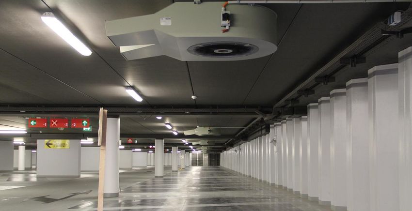
3Eco Park® Induction/Thrust Fans
‘Induction thrust fans will be of the twin discharge, low profile Centrifugal type. Casings will be constructed in galvanised
heavy-duty steel plate with powder-coated finish. Dependent on the car park configuration fans will have a minimum
thrust capacity of either 50 Newton’s or 100 Newton’s in fire mode. Fans will drop a maximum of 250 mm from soffit. and
be capable of operating on a 415v/ 3 ph /50hz supply. Fan Impellers will be narrow pattern centrifugal type balanced to
grade 6.3 as minimum.
The induction/ thrust fans shall be located in various positions within the car park above the drive lanes to ensure
sufficient air movement within the car park at all times. Mounting fans directly above parked vehicles or at the junction of
walls and soffit should be avoided. The fans shall be located within the structural depth and not encroach below the
specified headroom for the car park.
High Temperature Fans will be tested and certified to EN12101-3 for suitable operation at 300deg C for 1 hour the fans
must be CE marked and supplied and installed in accordance with BS 7346 -7-2006. Fans will be finished standard grey
or in RAL colour to suit architects design, developer’s preference or corporate policy. Units to be supplied with a lockable
isolator.
The induction fans shall be used to control the direction of the airflow within the car park, ensuring no stagnant areas
under normal ventilation conditions, and the correct movement of smoke flow in the event of fire.
Main Control Requirements
The control system shall be a fire rated critical system. Each fan shall be multi speed controlled by inverters located
within the MCC panel. The fans shall operate normally at low speed and switch to high speed for CO extraction and full
speed for smoke extract conditions when signalled by the fire alarm system or the appropriate monitoring system. The
fans shall have the capacity to operate on a programmed time switch signal, which shall be overridden by either a CO or
fire conditions
Carbon monoxide detectors should be fixed at appropriate places within the facility at a rate of one detector every 400m²
which will send the appropriate signal to the main panel selecting and increasing the speed of fans when CO levels
exceed 35ppm and 50ppm.
Full manual control of the system shall be provided at the fireman’s panel.
The complete control arrangements of the car park ventilation, smoke control override, auto changeover and alarm
signals shall be incorporated into an Open Protocol. Control panel PCB circuits are to be off the shelf non closed protocol
components.
CO Detection System
The installer shall provide CO detection and a control system to enable the fans to run at reduced volume at times of low
vehicular movement and at set levels of CO pollution.
Heat and Smoke Detection
The ventilation system main extract fans shall be automatically activated in fire mode and on receiving a signal from the
fire detection system. The induction fans will initially switch off for a period of 2 minutes to allow persons to locate
suitable escape routes and exit the facility. After the initial 2 minute delay the induction fans activate to guide smoke
pollution to the dedicated main extract point.
Multi criteria detection heads shall be used within the car park spaced appropriately in line with manufacturer’s standard
throughout the facility to reduce the risk of false alarms and to ensure early fire detection.
Fire Fighters Override Panel
A lockable fireman’s panel, to enable fire service personnel to switch to “Auto” or “off”, shall be provided at the entry to
the car park. The system shall provide additional control at the main panel
46 FAN RATING AND PERFORMANCE
In compliance with Building Regulation Approved Document B, the main extract fans shall be rated to extract a minimum
of 50% of the maximum airflow.
Quality / Certification
Fans are to be designed and manufactured with procedures as defined in BS EN ISO 9001-2000. All EEC directives will be
met.
Fans will be tested at elevated temperatures to the requirements of EN 12101-3: 2002.
Fans will be tested to ISO 5801: 1997 (airside performance) and BS 848 pt 10 1999.’
The Fans will be manufactured by: Parking Ventilation Equipment Ltd. 01422 88 66 99 or equivalent
7 CABLING
The specialist installer will run cables to all components and make final connections. The following table provides
information on the specification of cable used for Thrust Ventilation Systems.
Item Cable Specification
Power cable to main fans Pirelli FP600 or equivalent
Power cable to impulse fans Pirelli FP400 or equivalent
Signal cable to smoke detectors Pirelli FP200 or equivalent
Signal cable to CO detectors PVC YY
8 DESIGN CFD AND VELOCITY PROFILE DIAGRAMS
The system design will be verified at the technical submission stage by production of a CFD produced by an independent
Consultant specialising in the design of fire safety systems for car parks. The CFD will be produced in line with the
requirements of BS 7346-7. It will be essential to provide a full airflow velocity plume diagram as part of the technical
submission to confirm total coverage ensuring there are no stagnant areas
9 TESTING, COMMISSIONING & DOCUMENTATION
Balance the system and measure normal and boost mode airflow rates under normal operating conditions
Test airflow failure switches and critical alarm indication.
Test all detection devices
Test boost operations of extract fans and any motorised damper operation.
Test alternative power supply operation
Measure noise levels
Commissioning shall include the following
Commissioning fan system
Commissioning electrical panels
Commissioning of the CO detection system
Commissioning complete system
Commissioning shall be conducted in the presence of the approvals authority and consulting engineer along with any
other representatives. All commissioning procedures to follow the guidelines of BS 7346-6.
Following commissioning the specialist to provide full test certification including cable test records. Provide operation and
maintenance manuals in the form of hard copy , disc and PDF covering the whole operational sequence of the system
and recommending a test and maintain program. Manuals to contain installed drawings, verification checks and evidence
of client training.
A smoke generator shall be used to simulate air movement and to demonstrate the efficiency of each sequence of
operation.
The complete system to be supplied by HC PVE Ltd. Tel 0845 20 20 234. or equal and approved .
5You can also read