Smithsonian Facilities CAD Guidelines - April 2021 Edit indicators: Smithsonian Facilities CAD GUIDELINES
←
→
Page content transcription
If your browser does not render page correctly, please read the page content below
Smithsonian Facilities CAD GUIDELINES

Smithsonian Facilities

CAD Guidelines
April 2021

Edit indicators:

             All changes from the previous version of this document, dated September 2018,
             are highlighted with a vertical line, as shown here.

April 2021                                                                                   Page 1
Smithsonian Facilities CAD GUIDELINES

Table of Contents
Implementation of CAD ....................................................................................................................................... 3
  Introduction ....................................................................................................................................................... 3

Electronic Transmission Methods ........................................................................................................................ 4
  Introduction ....................................................................................................................................................... 4
  FTP Site ............................................................................................................................................................. 4
  E-mail ................................................................................................................................................................ 4
  Documentation................................................................................................................................................... 4

Sheet Drawing Submission Standards ................................................................................................................. 5
  Introduction ....................................................................................................................................................... 5
  File Format ........................................................................................................................................................ 5
  Sheet File ........................................................................................................................................................... 5
  Names................................................................................................................................................................ 5
  Sketches and Supplemental Drawing File Names ................................................................................................ 6
  Page Setups........................................................................................................................................................ 6
  Scale ................................................................................................................... Error! Bookmark not defined.
  Layers ................................................................................................................. Error! Bookmark not defined.
  Digital Signatures............................................................................................................................................... 6
  Lineweights ....................................................................................................................................................... 7
  Standard Cover Sheet & Title Block ................................................................................................................... 7
  SF Sheet Sizes.................................................................................................................................................... 7
  Text Sizes and Fonts .......................................................................................................................................... 8

Background Drawing Submission Standards ...................................................................................................... 9
  Introduction ....................................................................................................................................................... 9
  File Format ........................................................................................................................................................ 9
  Drawing Setup ................................................................................................................................................... 9
  File Naming ....................................................................................................................................................... 9
  Object Color .................................................................................................................................................... 10
  Units ................................................................................................................................................................ 10
  Blocks.............................................................................................................................................................. 11
  Lines and Line Types ....................................................................................................................................... 11
  Dimensions ...................................................................................................................................................... 11
  Layers .............................................................................................................................................................. 11
  Plot Style ......................................................................................................................................................... 11

Standard Base Plans ........................................................................................................................................... 12
  Introduction ..................................................................................................................................................... 12
  Layers .............................................................................................................................................................. 12

Appendix B: Discipline Codes for File Naming Conventions ............................................................................ 16

Appendix C: Required Symbols ......................................................................................................................... 19

April 2021                                                                                                                                                     Page 2
Smithsonian Facilities CAD GUIDELINES

Implementation of CAD

    Introduction The Smithsonian Institution (SI) maintains many facilities in the Washington DC area
                 and throughout the United States. Maintenance of CAD (Computer Aided Drafting
                 and Design) drawings for each of these facilities is the responsibility of Smithsonian
                 Facilities (SF), an organization that is responsible for both in-house design efforts and
                 administration of repair, renovation and new construction projects for the museums
                 and other facilities. The purpose of this manual is to define information, procedures,
                 and responsibilities relevant to CAD work completed by A/E consultants in order to
                 assure accurate and consistent work.

                    SF’s standards include guidelines for drawing appearance, CAD layering and
                    symbology, and the use of CAD-related software. Each is discussed in a separate
                    section of this document. Refer to the table of contents for specific information on a
                    particular topic.

April 2021                                                                                        Page 3
Smithsonian Facilities CAD GUIDELINES
Electronic Transmission Methods
Introduction Refer to the project Scope of Work to determine which type of transmission method is
required for each project submission.
FTP Site Due to the constraints of sending large files via e-mail, OCIO has established an FTP
site to use for transferring electronic documents between SF and outside
consultants. The FTP site acts like any other folder in Windows Explorer. To access
the site please obtain instructions from the project design manager.
To prevent unauthorized use of SI files, any files left on the FTP site for more
than 48 hours will be deleted. This should give everyone ample time to send and
receive daily work. Please make sure you have copies of your files stored on your
personal computer or on the secure internal network.
E-mail The size of attachments to e-mails on the Smithsonian network is limited to 3.5
megabytes total. Use of the FTP Site is recommended for larger transmissions.
Dropbox SI utilizes Dropbox for the transfer of large files. Please discuss with the Project
Design Manager to obtain shared folder access.
OneDrive SI utilizes OneDrive for the transfer of large files. Please discuss with the Project
Design Manager to obtain shared folder access.
Documentation SF Project Documentation form and Deliverables Matrix. These forms are similar in
nature to the GSA’s deliverable requirements. The Project Documentation Form
identifies the personnel responsible for the project, versions of software used in its
preparation, and any script files, non-AutoCAD entities (Fonts, Linetypes, Blocks, etc.)
used in drawing preparation. The Deliverables Matrix identifies each drawing
submitted by name, all external references by name, and the plot scale for each drawing.
Refer to Appendix A for examples of the forms.
April 2021 Page 4Smithsonian Facilities CAD GUIDELINES
Sheet Drawing Submission Standards
Introduction These drawings serve as the official project record. Each sheet represents one and
only one plotted drawing.
File Format All sheet drawing deliverables shall be submitted in both Adobe Acrobat format
(.PDF), and in their native software format. Native format may be either AutoCAD
or BIM authoring software.
PDF Files: All graphics in PDF files must be measurable/snap-able using markup
tools in software such as Adobe Acrobat Professional. All drawing text in PDF files
must be searchable. There shall be one PDF file per printed sheet in the set.
AutoCAD: Drawing files shall be AutoCAD 2018 format or earlier.
There shall be one AutoCAD file per printed sheet in the set, and X-refs shall be
bound. Depending of scope of the project as single AutoCAD with Multiple Paper
Space Tabs may be allowed, discuss with COTR at Project Kick-Off Meeting.
See SMITHSONIAN BIM GUIDELINES for all projects that require BIM.
Sheet File Sheet drawing files represent the finished construction documents for a project, they
Names are designated following sheet naming conventions that correspond to the drawing
number for each sheet.
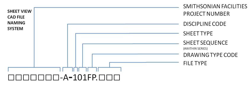
The naming convention is as follows: [Smithsonian Facilities Project Number][-
][Discipline Code][-]Sheet Type][Sheet Sequence][Drawing Type Code][.][File Type]
PDF: 1234567-A-101FP.pdf
AutoCAD: 1234567-A-101FP.dwg
Represents the twelfth sheet of architectural elevations in a set of drawings for a
project # 1234567.
See Appendix B for a list of sheet sequence numbers, discipline codes, and typical
drawing type codes for each discipline.
April 2021 Page 5Smithsonian Facilities CAD GUIDELINES
Sketches and supplemental drawings shall be named in a similar manner.
• Sketch files created during design should be named with the two letter
designation SK first, discipline code next, then the next consecutive number
of a series:
0403110-SKI014.pdf
(Fourteenth in a series of Interiors sketches)
• Drawings created as part of an addendum, or supplemental drawings, should
be named with the two letter designation SD first, discipline code next, then
the sheet number that is referred to, and the revision number:
0403110-SDM102.3.pdf
(Supplemental drawing for mechanical sheet 102, revision number 3)
Sketches and Pages must be oriented, when displayed on-screen, in the same direction as the hard-
Supplemental copy would be read.
Drawing File
Names
Page Setups All PDF files must be created as if being plotted at full size on the same size paper
being used for the contract documents. When printed on the appropriate sized paper,
all drawing scales shown in the drawing should be accurate when measured with
mechanical drafting tools.
Digital Acceptable lineweights on drawing deliverables occupy a range from about 0.18 mm
Signatures to 1.0 mm when plotted full-size.
Only use the highest range of lineweights to indicate major dividing lines such as
section-cuts and match lines.
The narrowest lineweights should be used for highly detailed items and column
grids.
Within the middle-range, be sure to giving greater weight to new construction when
occupying the same plan as existing construction. Give even greater weight to
annotations.
On engineering drawings which reuse the partitions, ceiling grids, etc. from the
architectural plans, use 50% to 75% shading on the architectural elements, to
increase the readability of things like ductwork, piping, etc.
April 2021 Page 6Smithsonian Facilities CAD GUIDELINES
Lineweights The standard Smithsonian title block shall be used on every sheet. The first sheet
(cover sheet) in any set of drawings shall be designated the Title / Cover Sheet and
will be numbered according to the process outlined in the previous section. It shall
contain the SF approval block directly above the title block.
All of the title block parameters are block attributes. To edit the attributes, use
AutoCAD’s DDATTE or AT command. Do not change the text size in the drawing
provided (except for the A/E logo and information pertinent to consultants).
Please refer to the Special Conditions for A/E services for logo location and size, as
well as the identification code.
All Smithsonian title blocks are available for download at the SF website, A/E Center.
Standard Cover
Sheet & Title One of the following sheet sizes should be used for all projects. The preferred standard
Block is Arch D (24 x 36 in). If a project requires an alternate size, approval must be
obtained from the COTR. All title blocks and cover sheets are provided in metric and
imperial versions. All drawings in a submission shall be produced in a consistent
format and drawing size. Sketches should be one of the Letter or Tabloid formats.
Paper Size Dimensions File Name
Arch D (Standard) 24 by 36 inches Cover: ST-CVR_in.dwg
Sheet: ST-TTL_in.dwg
610 by 914 mm Cover: ST-CVR_mm.dwg
Sheet: ST-TTL_mm.dwg
Arch E 36 by 48 inches Cover: E-CVR_in.dwg
Sheet: E-TTL_in.dwg
914 by 1219 mm Cover: E-CVR_mm.dwg
Sheet: E-TTL_mm.dwg
Arch F (Arch 30) 30 by 42 inches Cover: F-CVR_in.dwg
Sheet: F-TTL_in.dwg
762 by 1067 mm Cover: F-CVR_mm.dwg
Sheet: F-TTL_mm.dwg
Tabloid 11 by 17 inches Vertical: 11x17-V_in.dwg
Horizontal: 11x17-H_in.dwg
279 by 432 mm Vertical: 11x17-V_mm.dwg
Horizontal: 11x17-H_mm.dwg
Letter 8½ by 11 inches Portrait: 8x11-P_in.dwg
Landscape: 8x11-L_in.dwg
216 by 279 mm Portrait: 8x11-P_mm.dwg
Landscape: 8x11-L_mm.dwg
SF Sheet Sizes For the purpose of microfilm storage and reduced document reading, all drawing notes
shall be given in simple AutoCAD text fonts or True-Type fonts Arial, Times or
Verdana. Fonts that are not standard to AutoCAD or True-Type fonts Arial, Times or
Verdana are not acceptable for use in SF drawings.
April 2021 Page 7Smithsonian Facilities CAD GUIDELINES
Upper-case lettering shall be used on drawings unless lower-case letters are required
Text Sizes and to conform to other established standards, equipment nomenclature, or marking.
Fonts
All construction document main titles shall use Roman Duplex (ROMAND) font or
True-Type font Arial. All other lettering shall be Roman Simplex (ROMANS) font or
True-Type fonts Arial, Times or Verdana.
The plotted text strings for main drawing titles shall be no smaller than 6.4 (1/4 inch)
mm high. All other lettering shall be a minimum of 3.2 mm (1/8 inch) high with a
2mm (1/16 inch) space between lines of text.
Symbols Always use the standard symbols listed in Appendix C. Do not redefine these symbols.
No substitutions will be permitted.
April 2021 Page 8Smithsonian Facilities CAD GUIDELINES
Background Drawing Submission Standards
Introduction Background drawings are by definition, re-usable. The requirements in this section
are intended to be applied to drawings for new buildings. Areas where choices can
be made are left up to the discretion of the A/E. For existing buildings, the
Smithsonian will provide drawings at project startup. While editing these SI-
supplied background drawings, the A/E must maintain the standards in keeping with
the way the drawings were received.
File Format All background drawing deliverables shall be submitted in their native software
format. These must adhere to the same standards described in the File Format section
with the Sheet Drawing Submission Standards described above.
Drawing Setup The origin of every file in the background drawing submission shall be at coordinates
(0, 0, 0) located at the lowest left-hand column line intersection that is consistent on
each floor of a given building.
Drawings inserted into one another at (0, 0, 0) shall always accurately represent the
vertical alignment of floors in the built reality of the building.
There must be a one-to-one relationship between files and floors.
Areas of a floor that occur at different elevations relative to each other without
overlapping should be in the same drawing. Areas that occur as mezzanines, no matter
how small, should be relegated to a separate drawing, with the full building column
grid included to help with spatial reference.
File Naming Each file name has four components: the full building number (minus the hyphen), a
one-to-two-character discipline code, a two-character drawing type code and 2 to 3
characters that identify the floor. For example, a drawing named
031001-A-FPF1.dwg
Represents the first floor architectural background drawing for National Museum of
American History (031) – Main Building (001).
April 2021 Page 9Smithsonian Facilities CAD GUIDELINES
See Appendix B for a list of sheet sequence numbers, discipline codes, and typical
drawing type codes for each discipline.
Floor identification is dependent on what the occupants of a particular building choose
to call the various levels, but certain terms appear regularly. The following are
examples of abbreviations already in use at the Smithsonian:
Third Floor: F3
Basement: B1
Parking Level 2: P2
Lower Level: LL
First Floor Mezzanine: F1M
Penthouse: PH
Object Color Avoid changing the color of an object, all objects shall be created with all properties
BYLAYER.
Drawing If the CAD drawings are based on well-dimensioned archives, the accuracy shall be
Techniques, +/- 25 mm between major structural elements. Wall thickness shall be to the nearest
Accuracy and 10 mm. The tolerance for furniture placement is typically 100 mm. The Smithsonian
Consistency will specify procedures and accuracy requirements for drawings based on field
verification and for new construction drawings.
Do not change the drawing's insertion point, or origin. Temporary changes in the
insertion point are permitted as long as the default (0, 0) coordinate is reestablished
prior to drawing submission. The insertion point is used as the reference point for
connecting various drawing sections together, as well as for merging
drawings/reference files from various disciplines.
Prior to submission, all final drawings shall be purged of all the un-referenced line
types, blocks, layers, views, shapes, and text styles and all CAD drawings shall be
saved and submitted with the zoom display set to drawing "extents."
Units Drawings submitted to SF may be metric or imperial, which is determined by the
COTR on a project-by-project basis. Metric drawings shall have the units set to
decimal, with a precision of 0.0. Block insertion units shall be millimeters. Imperial
drawings shall have the units set to architectural, with a precision of 1/64.” Block
insertion units shall be inches.
April 2021 Page 10Smithsonian Facilities CAD GUIDELINES
Blocks Blocks shall be created for all entities that are used repeatedly on a drawing, such as
doors, windows, furniture and other plan elements. Blocks should be created with
logical insertion points that are consistent with their placement in a drawing, such as
the bottom left corner, center of circle or radius, etc.
Blocks should be inserted on the correct layer (i.e. doors should be inserted on layer
A-DOOR-).
Any temporary blocks used in drawing creation should be exploded and purged out of
the drawings.
When defining new blocks, they shall be defined on layer "0" with the color and line
type parameters set to BYLAYER.
Lines and Line All entities shall be drawn with the LINE command or POLYLINE command with a
Types "0" thickness and a “0” elevation. Walls are to be drawn with two lines the appropriate
distance apart, not as a single polyline with thickness. Line weight will be assigned in
plotting.
All lines must properly connect, i.e. corners should meet without overshooting.
Do not duplicate lines. Construction lines should be placed on a separate non-plotting
layer.
Always use the AutoCAD default line types found in ACAD.LIN. Any new line types
shall be approved by the SF Design Manager prior to use.
Dimensions Background Drawings, by definition, contain few dimensions. When dimensions are
required by the SOW, they shall be associative.
Dimensions should never be exploded, and text may only be entered manually if the
dimension is intended to be an approximate, minimum, or maximum distance.
Layers Layer names must adhere to the most recent version of the AIA Layer Guidelines, as
included in the National CAD Standard.
Building elements must be placed on the correct layers. Do not repeat similar
information among different layers.
Do not store information on Layer "0."
Plot Style Smithsonian Facilities utilizes “Monochrome.ctb” as the standard.
April 2021 Page 11Smithsonian Facilities CAD GUIDELINES
Standard Base Plans
* The following requirements refer only to AutoCAD drawings. See Smithsonian BIM
Guidelines for all projects that require BIM.
Introduction SF maintains drawings that are basically a subset of the Architectural Base Plans, with
standardized Layer Naming, Contents of the layers, and Graphics that depict the
content. The Standard Base Plans describe the configuration of the facility inventory,
and provide a single foundation for the wide range of work on facilities:
• Planning/Design activities, including defining Existing Conditions
• Operations, Maintenance, Security, etc.
• As-Built Drawings
• Display of database information on drawings.
For this reason, the following requirements will be enforced with particular stringency
for all new and existing drawings that fall within the category of Standard Base Plans.
Layers The following chart list the layers for site plans and floor plans that are considered the
Standard Base Plans. Only these layers are required to meet the specifications of this
section. This is not an all-inclusive list, please refer to National CAD Standards for
acceptable laying standards.
Site Plan Layers Description Linetype Color
C-BLDG-OTLN Building Footprints Continuous W/7
C-PKNG-OTLN Parking Lots Continuous C/4
C-PKNG-CURB Parking Curbs and Gutters Continuous G/3
C-PROP-LINE Property Lines (check Benchmarks) Continuous Y/2
C-ROAD-OTLN Roads Continuous C/4
C-ROAD-CURB Curbs Continuous M/6
L-PLNT-TREE Trees Continuous 83
L-PLNT-GRND Ground Covers & Vines Continuous 82
L-PLNT-BEDS Landscaping Beds Continuous M/6
L-PLNT-BUSH Bushes and Shrubs Continuous 83
L-PLNT-TURF Lawn Areas Continuous 23
L-SITE-BRDG Bridges Continuous 22
L-SITE-EWAT Water features Continuous 162
L-SITE-FENC Fencing Continuous Y/2
L-SITE-DECK Decks Continuous 232
L-SITE-POOL Pools & Spas Continuous 162
L-SITE-ROCK Boulders and cobble Continuous R/1
L-SITE-RTWL Retaining Walls Continuous C/4
L-SITE-SPRT Sports Fields Continuous Y/2
L-SITE-WALK Walks & Steps Continuous R/1
April 2021 Page 12Smithsonian Facilities CAD GUIDELINES
Base Plan Layers Description Linetype Color
A-AREA-IDEN Room Numbers Continuous W/7
A-DOOR-FRAM Door Frames Continuous M/6
A-DOOR-FULL Full-height doors Continuous G/3
A-DOOR-GLAZ Door Glazing Continuous B/5
A-DOOR-PRHT Partial-height doors Continuous M/6
A-EXBT Exhibit Continuous R/1
A-EXBT-WALL Exhibit Wall Continuous 40
A-FLOR-EVTR Elevators, wheelchair lifts Continuous Y/2
A-FLOR-LEVL Floor level changes, shafts, ramps Continuous M/6
A-FLOR-OTLN Building / Gross Area Polyline Continuous 40
A-FLOR-OTLN-RPRM Room / Space Area Polyline Continuous M/6
A-FLOR-OVHD Overhead items ACAD_ISO02W100 Gr/8
A-FLOR-SPCL Architectural specialties (e.g. toilet room Continuous G/3
accessories, display cases)
A-FLOR-STRS Stairs, escalators Continuous Y/2
A-FLOR-TPTN Toilet room partitions Continuous R/1
A-GLAZ-CURT Curtain Wall Panels and System Continuous B/5
A-GLAZ-PRHT Window glazing Continuous R/1
A-GLAZ-SILL Window sills Continuous B/5
A-ROOF Parapet walls (for reference on partial Continuous Gr/8
floors)
A-WALL-CWMG Curtain wall mullions Continuous R/1
A-WALL-FENC Fence Continuous R/1
A-WALL-FNDN Foundation Wall Continuous G/3
A-WALL-FULL-EXTR Exterior Walls Continuous Y/2
A-WALL-FULL-INTR Full-height Interior Walls Continuous G/3
A-WALL-MOVE Movable partitions Continuous B/5
A-WALL-PRHT Partial-height walls Continuous R/1
S-COLS-PRIM Primary columns Continuous M/6
S-COLS-SCND Secondary columns Continuous Y/2
A-AREA-LINE Lines defining room areas that are not Continuous C/4
walls
P-SANR-FIXT Plumbing Fixtures Continuous M/6
A-FLOR-HRAL Handrails Continuous R/1
A-FLOR-WDWK Built-in cabinets and counters Continuous G/3
A-WALL-HEAD Door headers Continuous R/1
I-FURN Furniture Continuous B/5
I-FURN-PNLS Systems Furniture Continuous B/5
S-GRID-HORZ Horizontal column grid lines ACAD_ISO08W100 B/5
S-GRID-IDEN Column identifiers Continuous R/1
S-GRID-VERT Vertical column grid lines ACAD_ISO08W100 B/5
April 2021 Page 13Smithsonian Facilities CAD GUIDELINES Appendix A: Project and Drawing Documentation Report and Deliverables Matrix Below are representations of typical Drawing Documentation Report and Deliverables Matrix that would accompany a required electronic deliverable. April 2021 Page 14
Smithsonian Facilities CAD GUIDELINES

    PROJECT NAME - PROJECT LOCATION                                                                                                 XXXX
    DELIVERABLES MATRIX                                                                                                        BUILDING NO

    Building Name:        xxxxx                               Smithsonian COTR:                  xxxx
    Building Address:     xxxxx                         Smithsonian COTR Phone:                  xxxx

                                                                          Sheet Size:            xxxx
    A/E name:             xxxxx                                         File Format:             xxxx
    Work order no.:       xxxxx                                           No of Files:           xxxx
    A/E contact:          xxxxx                                   Total File Volume:             xxxx
    A/E contact phone:    xxxxx                                  Date of Submission:             xxxx

     SHEET      NO/       SHEET TITLE                FILE NAME      XREFS                PLOT    SUBJECT
              Total No.                                             FILE NAMES           SCALE

     G-001      1/22      COVER SHEET                G-001.dwg                           1=1     Plot Sheet
                                                                    G-SP.dwg                     Vicinity Plan

     G-002      2/22      SYMBOLS & ABBREVIATIONS    G-002.dwg                           1=1     Plot Sheet

     A-101      3/22      EAST ENTRY REMODEL PLAN    A-101.dwg                           1=1     Plot Sheet
                                                                    A-FP01.dwg                   1st Floor plan & demo plan
                                                                    A-DT014a.dwg                 1/4" Drawings

     A-501      4/22      DETAILS                    A-501.dwg                           1=1     Plot Sheet
                                                                    A-DT034a.dwg                 3/4" Details
                                                                    A-DT112a.dwg                 1 1/2" Details
                                                                    A-DT300a.dwg                 3" Details

     A-502      5/22      DETAILS                    A-502.dwg                           1=1     Plot Sheet
                                                                    A-DT014b.dwg                 1/4" Details
                                                                    A-DT112b.dwg                 1 1/2" Details

      L-101     6/22      EXISTING SITE CONDITIONS   L-101.dwg                           1=1     Plot Sheet
                                                                    L-SP.dwg                     Exist. Site Information
                                                                    L-SH.dwg                     Landscape Legend
                                                                    G-SH.dwg                     Detail Box Background
                                                                    C-UPsan.dwg                  San. Sewer Plan
                                                                    C-UPssw.dwg                  Storm Sewer Plan
                                                                    C-UPwat.dwg                  Water Utility Plan

      L-102     7/22      SITE DEMOLITION            L-102.dwg                           1=1     Plot Sheet
                                                                    L-SP.dwg                     Exist. Site Information
                                                                    L-DP.dwg                     Site Demolition plan
                                                                    G-SH.dwg                     Detail Box Background
                                                                    L-SPa.dwg                    Limits of Construction Plan
                                                                    L-SHa.dwg                    Landscape Notes

April 2021                                                                                                                           Page 15
Smithsonian Facilities CAD GUIDELINES
Appendix B:
Discipline Codes
Discipline Designator Description Discipline Designator Description
General G- All General Landscape LI Landscape Irrigation
GI General Information LL Landscape Lighting
GC General Contract LP Landscape Planting
GR General Resource LR Landscape Relocation
Survey / V- All Survey/Mapping LS Landscape Site
Mapping VA Aerial Survey Structural S- All Structural
VF Field Survey SD Structural Demolition
VH* Hydrographic Survey SS Structural Site
VI Digital Survey SB Structural Substructure
VU Combined Utilities SF Structural Framing
Civil C- All Civil SR* Structural Reinforcement
CB* Civil Beach Re-nourishment ST* Superstructure
CD Civil Demolition SC* Structural Components
CE* Civil Ecosystem Restoration Architectural A- All Architectural
CF* Civil Flood Control AS Architectural Site
CG Civil Grading AD Architectural Demolition
CI Civil Improvements AE Architectural Elements
CN* Civil Navigation AI Architectural Interiors
CO* Civil Operation and AF Architectural Finishes
Maintenance
CP Civil Paving AG Architectural Graphics
CH* Civil Shore Protection AL** Life Safety
CR* Civil Recreation Interiors I- All Interiors
CS Civil Site ID Interior Demolition
CX* Civil Security IN Interior Design
CT Civil Transportation IF Interior Furnishings
CU Civil Utilities IG Interior Graphics
Civil Works W-** Civil Works SI Custom EX** Exhibits
Utilities U- All Other Utilities AA** Accessibility
Geotechnical B- All Geotechnical EV** Elevator
Landscape L- All Landscape GS** Graphics
LD Landscape Demolition SS** Special – Systems
LG Landscape Grading Historic PH** Historic Preservation
Preservation
Note: * = Not in NCS 5.0; **=SI Only Discipline Code Source: USACE A/E/C CAD Standard Release 5.0
April 2021 Page 16Smithsonian Facilities CAD GUIDELINES
Discipline Code Table, continued
Discipline Designator Description Discipline Designato Description
r
Equipment Q- All Equipment Fire FD** Fire Protection Demolition
Protection
QA Athletic Equipment Electrical E- All Electrical
QB Bank Equipment EA* Elec. Airfield Lighting & Nav-
aids
QC Dry Cleaning Equipment ES Electrical Site
QD Detention Equipment EC* Electrical Cathodic Protection
QE Educational Equipment EG* Electrical Grounding
QF Food Service Equipment ED Electrical Demolition
QH Hospital Equipment EP Electrical Interior Power
QL Laboratory Equipment EL Electrical Interior Lighting
QM Maintenance Equipment EI Electrical Instrumentation
QP Parking Lot Equipment EY Elec. Interior Auxiliary Systems
QR Retail Equipment ET Electrical Telecommunications
QS Site Equipment Tele- T- All Telecommunications
QT Theatrical Equipment communi- TD* Telecom. Demolition
QV Video/Photographic Equip.
cations TA Audio Visual
QY Security Equipment TC Clock and Program
Mechanical M- All Mechanical TI Intercom
MS Mechanical Site TM Monitoring
MD Mechanical Demolition TN Data Networks
MH Mechanical HVAC TS* Supervisory Control & Data
Acquisition (SCADA) systems &
equipment
MP Mechanical Piping TT Telephone
MI Mechanical TY Security (Access control&
Instrumentation Alarms)
MY* Mechanical Hydraulic Sys. Hazardous H- Hazardous Materials
Plumbing P- All Plumbing Materials HA Asbestos
PS Plumbing Site HC Chemicals
PD Plumbing Demolition HL Lead
PP Plumbing Piping HP PCB
PQ Plumbing Equipment HR Refrigerants
PL Plumbing Shop Z- Contractor/Shop Dwgs.
Drawings
Fire F- All Fire Protection Operations O- Operations
Protection FA Fire Detection and Alarm Others X- Other Disciplines
FX Fire Suppression
Note: * = Not in NCS 5.0; **=SI Only Discipline Code Source: USACE A/E/C CAD Standard Release 5.0
April 2021 Page 17Smithsonian Facilities CAD GUIDELINES
Discipline Code Table, continued
Discipline Designato Description Discipline Designator Description
r
Process D- All Process Resource R- All Resource
DS Process Site RC Resource Civil
DD Process Demolition RS Resource Structural
DL Process Liquids RA Resource Architectural
DG Process Gases RM Resource Mechanical
DP Process Piping RE Resource Electrical
DQ Process Equipment
DE Process Electrical
DI Process Instrumentation
Note: * = Not in NCS 5.0; **=SI Only Discipline Code Source: USACE A/E/C CAD Standard Release 5.0
Drawing Type Codes
Designator Description Designator Description
FP Floor Plan Structural
DP Demolition Plan MP Framing Plan
SP Site Plan NP Foundation Plan
QP Equipment Plan Architectural/Interiors
All Disciplines
XP Existing Plan EP Enlarged Plan
RO Roof Plan CP Ceiling Plan
EL Elevation RP Furniture Plan
SC Section NP Finish Plans
DT Detail VP Evacuation Plan
SH Schedule Mechanical
Discipline Specific
3D Isometric/3D CP Control Plan
DG Diagrams HP HVAC - Ductwork Plan
General PP Piping Plan
BS Border Sheet Electrical
KP Key Plan CP Communication
CS Cover Sheet GP Grounding
Discipline Specific
Civil LP Lighting
EP Environmental Plan PP Power
GP Grading Plan Plumbing
RP Road/Topographic Plan PP Plumbing Plan
SV Survey Fire – Protection
UP Utility Plan KP Sprinkler Plan
Telecommunications
DP Data
TP Telephone
April 2021 Page 18Smithsonian Facilities CAD GUIDELINES
Sheet Sequence Numbers
000 General (Symbols, Legends, Notes) 500 Details
100 Plans (including Reflected Ceiling Plans) 600 Schedules and Diagrams
200 Elevations 700 User Defined (Elevators and Stair plans, details,
sections)
300 Sections 800 User Defined (non-architecture)
400 Enlarged Views (plans, sections, elevations) 900 3D Views, Interior Details, Partition Types,
Window Types
Appendix C: Required Symbols
The following symbols are available from SF Website – A/E Center.
April 2021 Page 19Smithsonian Facilities CAD GUIDELINES April 2021 Page 20
You can also read