The Signal-to-Noise Indicator or How to Navigate the 'Bermuda Triangle'

Page created by Morris Navarro
 
CONTINUE READING
The Signal-to-Noise Indicator or How to Navigate the 'Bermuda Triangle'
How-I-do-it

The Signal-to-Noise Indicator or
How to Navigate the ‘Bermuda Triangle’
Joachim Graessner, Dipl. Ing.

Siemens Healthcare, Hamburg, Germany

1                                                                                                    Which parameters influence
                              Relative Signal-to-Noise                                               the SNR indicator?
                                                                                                     There are several parameters which alter
                                                                                                     the signal S. Or, looking at the equation,
                                                                                                     the signal S is proportional to certain
                                                                                                     parameters.
                                                                                                     S2D ~ 1/sqrt (BW) * Δx *Δy* Δz * sqrt
                                                                                                     (AC * Npe)
                                                                                                     S3D ~ 1/sqrt (BW) * Δx *Δy* Δz * sqrt
                                                                                                     (AC * Npe * N3D)
                                                                                                     ■ BW – bandwidth in Hz/pixel
                                                                                                     ■ Δx – inplane resolution in x-direction:
                                                                                                        FOVx / Nre
                                                                                                     ■ Δy – inplane resolution in y-direction:
                                                                                                        FOVy / Npe
                                                                                                     ■ Δz – Slice thickness or partition thick-
          Scan time                                                Resolution                           ness in 3D case: slab-thickness/ N3D
                                                                                                     ■ AC – Averages: number of excitations
    1 ‘Bermuda Triangle’ of dependant MR quantities.                                                    per same encoding step
                                                                                                     ■ Nre – Base matrix size in read direction
                                                                                                     ■ Npe – Number of phase encoding steps
We observe quite often that people feel           sity of the noise (SNR) typically mea-             ■ N3D – Number of phase encoding steps
uneasy with the interpretation of the             sured in the air outside the body.                    in 3D direction or Z-direction
numbers the signal-to-noise (S/N) indi-                                                              For our problem we are only looking for
cator shows on the syngo program-card.            Why is the SNR relative?                           dependencies with respect to resolution,
“May I change the protocol although the           The SNR indicator of a saved protocol              i.e. voxel size, total number of acquired
SNR indicator shows a value of 0.3?”              always shows the value 1.00 or 100%.               echoes (number of phase encoding
“Why does oversampling improve S/N?               Changing certain MR parameters                     steps), number of averages (number of
The larger FOV only covers more air.”             changes this indicator value but only rel-         excitations) and readout-properties such
Such questions and many more will be              ative to the initially stored version of this      as bandwidth per pixel. Parameters
answered in this article. We will take            protocol. After saving the performed               determining contrast like TE, TR, TI and
away the mystery of parameter changes             parameter changes the SNR indicator                flip angle as well as the sequence type,
and explain their mutual dependencies             switches back to the value of 1.00. Do             field strength and coil type do not play
(Fig. 1).                                         not use this value for comparisons                 any role for the SNR indicator (Fig. 2).
                                                  between different protocols!
What is signal-to-noise?
The total MR-signal is a mixture of the
signal from the pure MR experiment plus
thermal noise and other sources of                 2

noise. A measure of quality for a medical
image is the ratio of the signal-intensity             2 Headline of the parameter card in the syngo MR B/C/D-software versions.
in the object divided by the signal-inten-

144 MAGNETOM Flash · 1/2012 · www.siemens.com/magnetom-world
The Signal-to-Noise Indicator or How to Navigate the 'Bermuda Triangle'
How-I-do-it

What does the resolution                          What does the scan time indi-                    ■   Prep – preparation pulses at the begin-
indicator show?                                   cator show?                                          ning of a sequence to bring the mag-
                                                                                                       netization into steady state. This takes
In syngo MR A/B/C software versions you           The measurement time (TA) depends on                 a few seconds.
get with mouse-over on the resolution             the product of TR time, number of aver-          ■   Intro – 3 gradient knockings at the
field a display of values down to an accu-        ages AC, number of phase encodings,                  beginning of a protocol to warn the
racy of 1/100 mm. In the syngo MR                 and number of 3D encodings and may                   patient; can be switched off for
D-version you additionally get a display          be divided by the Turbo factor TF, EPI               breath-hold series on the sequence
of the measured and the calculated                factor and time saving factors from sam-             card.
resolution (Fig. 3).                              pling strategies like iPAT and Halffourier.
Example:                                          TA2D = [(TR * AC * Npe) / (TF * PAT2D)] +        What do these values tell me?
1.00 x 1.00 x 1.00 mm = Δx * Δy * Δz              Prep + Intro                                     Fortunately the MR software does all
                                                  TA3D = [(TR * AC * Npe * N3D) /                  these calculations for you. When chang-
                                                  (TF x PAT2D * PAT3D)] + Prep + Intro             ing parameters of a given protocol
                                                                                                   which already delivered decent image
3                                                                                                  quality you get an idea of how the scan
                                                                                                   time, the resolution and the relative SNR
                                                                                                   change compared to the initial protocol
                                                                                                   setup. A protocol with a lot of reserve in
                                                                                                   SNR can still deliver good image quality,
    3 Mouse-over on voxel size in the syngo MR D-software version.
                                                                                                   even with an SNR indicator on 0.1. But

     Table 1: Changing the number of phase encoding steps and averages
     affects scan time TA, pixel size and relative SNR.

    FOV       Matrix          AC        TA       Pixel size     Rel. SNR                                         Explanation
    (mm)      Npe x Nre                 a.u.     (mm2)          a.u.

    512       256 x 256       2         1        2x2            4.00                            4 times the pixel size

    256       128 x 128       2         0.5      2x2            2.83 = (4 / √2) = 2 * √2        4 times the pixel size and 2 times less Npe

    256       128 x 256       2         0.5      2x1            1.41 = (2 / √2) = √2            twice the pixel size, but 2 times less Npe

    256       256 x 256       4         2        1x1            1.41 = √2                       twice the number of ACs

    256       256 x 256       2         1        1x1            1.00                            start protocol (reference)

    256       256 x 256       1         0.5      1x1            0.71 = (1 / √2)                 half the number of ACs

    256       256 x 512       2         1        1 x 0.5        0.5                             half the pixel size

    256       512 x 512       2         2        0.5 x 0.5      0.35 = (0.25 * √2)              quarter pixel size, but 2 times more Npe

    128       256 x 256       2         1        0.5 x 0.5      0.25                            quarter pixel size

                                                                            MAGNETOM Flash · 1/2012 · www.siemens.com/magnetom-world         145
The Signal-to-Noise Indicator or How to Navigate the 'Bermuda Triangle'
How-I-do-it

4                                                                        when you already pushed resolution and
                                                                         scan time to a level where the images
                                                                         start to get noisy, a further change with
                                                                         a resulting SNR of 0.9 could result in an
                                                                         unacceptable quality. As said, the SNR
                                                                         indicator shows a relative quantity. It
                                                                         depends on the starting conditions.
                                                                         You will always have to sacrifice one or
                                                                         two items when optimizing the third
                                                                         one.
                                                                         Better resolution in less scan time with
                                                                         higher SNR is impossible unless you
                                                                         change the measurement conditions like
                                                                         field strength or type of RF coil.

                                                                         Table 1 gives an example:
                                                                         ■ Bandwidth and slice thickness are
                                                                           assumed constant
                                                                         ■ No iPAT and quadratic FOV

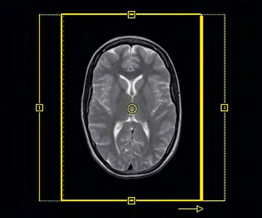
    4 33% phase oversampling applied on a 75% phase FOV.                 ■ Pixel size x slice thickness = Voxel size

                                                                         Obviously the factor square root of two
                                                                         (√2) plays an important role when
    Table 2: How MR parameters affect TA, resolution and SNR.            diminishing or enlarging certain MR
                                                                         parameters by a factor of two. Only
                                                                         alterations of the slice thickness change
    Parameter                       Measurement       Resolution   SNR   the SNR indicator linearly. All other
                                      time TA                            parameters go with the square root of
                                                                         the change factor up or down.
    Matrix
                                                                         Why does phase oversampling
                                                                         improve the S/N?
    Fields-of-view (FOV)                –                                Oversampling in phase direction
                                                                         acquires more encoding steps and thus
    Slice thickness                     –                                increases SNR. Each independently-sam-
                                                                         pled phase encoding step adds a portion
                                                                         to the total SNR. Each echo contains
    Bandwidth per pixel
                                      ( )*                 –             information about the whole image;
                                                                         there are no echoes which collect data
                                                                         in the air.
    Averages AC                                            –             Figure 4 shows a special case with 75%
                                                                         phase FOV combined with 33% phase
    Phase oversampling                                     –             oversampling (PhOS). Compared to
                                                                         100% phase FOV with no PhOS you have
                                                                         the same SNR, scan time and resolution.
    Rectangular FOV                                        –             The same is true for a setup with 100%
                                                                         PhOS and half the number of ACs or
    iPAT factor                                            –             instead iPAT = 2.

                                                                         Why does the SNR not increase
    Partial Fourier factor                                 –             with more reference lines in
                                                                         GRAPPA mode?
    * only if TR can be shortened
                                                                         Because the number of reference lines
                                                                         are not included in the formula. The

146 MAGNETOM Flash · 1/2012 · www.siemens.com/magnetom-world
How-I-do-it

   Table 3: Parameters for SNR discovery protocols.

                                     SE 2D                  TSE 2D                  GRE 3D                  GRE 2D

   Sequence name                     tse                    tse                     gre                     gre

   Dimension                         2D                     2D                      3D                      2D

   FOV read                          256                    256                     256                     256

   FOV phase                         100%                   100%                    100%                    100%

   Base resolution                   256                    256                     256                     256

   Phase resolution                  100%                   100%                    100%                    100%

   Slice thickness                   5 mm                   5 mm                    1 mm                    5 mm

   TR                                467 ms                 3050 ms                 5.5 ms                  235 ms

   TE                                12 ms                  107 ms                  2.35 ms                 5 ms

   AC                                2                      2                       2                       2

   iPAT                              none                   none                    none                    none

   Bandwidth                         130                    130                     390                     260

   Slice/Slices per slab             5                      10                      64                      5

   Flipangle                         90                     180                     25                      70

   Turbo factor                      1                      9                       n.a.                    n.a.

   Introduction                      deselect               deselect                deselect                deselect

   Coil                              8 /12 /16-             channel                 head                    coil

   TA                                4:00 min               3:00 min                3:00 min                2:00 min

   Resolution                        1.0 x 1.0 x 5.0        1.0 x 1.0 x 5.0         1.0 x 1.0 x 1.0         1.0 x 1.0 x 5.0

   Rel. SNR                          1.00                   1.00                    1.00                    1.00

same is true for interpolation. But the      and gain some scan time if appropriate
                                                                                           How can I get a feeling for the
SNR actually benefits in most sequences      for the contrast.                             amount of change in the SNR
from the additionally sampled number                                                       indicator?
of reference lines using the ‘integrated’    Is there a rule of thumb for                  Generate a protocol with the parameters
mode.                                        changes in the SNR indicator?                 shown in Table 3, save it and than play
                                             A red arrow in Table 2 indicates for both     around with the MR parameters and dis-
Why does allowed partial                     directions a drawback compared to our         cover their influence on SNR, TA and res-
Fourier not change scan time                 positive expectations of shorter scan         olution. The TRs were chosen that way
in a TSE sequence?                           times, better resolution and SNR. There       to get round scan times, which will have
Partial Fourier in a TSE sequence only       is always at least one red arrow accom-       slight deviations when changing the
shortens the echo train length. This         panying a black arrow.                        number of averages AC. These few sec-
gives you the opportunity to shorten TR                                                    onds are due to the preparation phase at

                                                                     MAGNETOM Flash · 1/2012 · www.siemens.com/magnetom-world   147
How-I-do-it

     Table 4: Influence of the voxel size on total volume and SNR.

    SVS voxel size                        approx. UI values                     Volume                                 Rel. SNR
    (mm3)                                 (mm3)                                 (cm3)                                  a.u.

    20 x 20 x 20                          20 x 20 x 20                          8                                      1.00

    18.1 x 18.1 x 18.1                    18 x 18 x 18                          6                                      0.75

    15.9 x 15.9 x 15.9                    16 x 16 x 16                          4                                      0.5

    12.6 x 12.6 x 12.6                    13 x 13 x 13                          2                                      0.25

    10 x 10 x 10                          10 x 10 x 10                          1                                      0.125

    7.9 x 7.9 x 7.9                       8x8x8                                 0.5                                    0.063

    6.3 x 6.3 x 6.3                       6x6x6                                 0.25                                   0.031

    5x5x5                                 5x5x5                                 0.125                                  0.016

the very beginning of a protocol which
                                                                                              k Visit www.siemens.
is played out only once.                                                                      com/magnetom-world
                                                                                              to download training
Is there anything different with                                                              files in .edx format. Train-
spectroscopy protocols?                                                                       ing files are available for
                                                                                              software versions syngo
In single voxel spectroscopy (SVS) you
                                                                                              MR D11D, syngo MR B15
have to be aware of the fact that a slight                                                    and syngo MR B17.
decrease in the side length of a single
voxel will result in a large change to the
measured volume, i.e. dramatic
decrease in SNR, which can rarely be
compensated by an increase of averages
(Table 4). CSI protocols can deliver much
smaller voxels than SVS due to higher
number of encoding steps in two or
three dimensions. But this has to be
paid for by longer scan times and a more
global shim situation.

  References                                         5 “MRI the Basics”: Hashemi, Bradley, Lisanti; LWW        Contact
  Recommended literature for the curious reader in     2010.                                                   Joachim Graessner, Dipl.Ing.
  the order of increasing physical depth:            6 “MRI from Picture to Proton”: McRobbie, Moore,          Siemens AG Healthcare
1 “Magnets, Spins and Resonances”; Siemens 2003.       Graves, Prince; Cambridge 2007.                         GER H IM BM MR
2 “Magnets, Flow and Artifacts”; Siemens 2004.                                                                 Lindenplatz 2
3 “The Physics of Clinical MR Taught Through Imag-     Especially recommended for the German                   20099 Hamburg
  es”: Runge, Nitz, Schmeets; Thieme 2008.             speaking community:                                     Germany
4 “Questions & Answers in MRI”: Elster, Burdette;    7 „Praxiskurs MRT“: Nitz, Runge; Thieme 2011.             joachim.graessner@siemens.com
  Mosby 2001.                                        8 „MRT-Guide für MTRA/RT“: Nitz; Thieme 2012.

148 MAGNETOM Flash · 1/2012 · www.siemens.com/magnetom-world
You can also read