12 Industrial Case Study: Architectural Knowledge in an SOA Infrastructure Reference Architecture
←
→
Page content transcription
If your browser does not render page correctly, please read the page content below
12 Industrial Case Study: Architectural
Knowledge in an SOA Infrastructure Reference
Architecture

By Olaf Zimmermann, Petra Kopp, and Stefan Pappe © 2009, IBM Corporation.

In this chapter, we present an industrial case study for the creation and usage of
architectural knowledge.
    To establish the context of our usage of architectural knowledge, we introduce
business domain, service portfolio, and knowledge management approach of the
company involved in the case in a first section. In this first section, we briefly re-
view general architectural concepts such as viewpoints, methods, and reference
architectures. Not all of these concepts pertain to architectural knowledge explic-
itly; however, they helped us to create and leverage such knowledge successfully.
An understanding of our usage of these concepts helps to appreciate the central
role of architectural knowledge in the case. As a reader who is familiar with these
concepts and is primarily interested in our usage of architectural knowledge, as
opposed to its context in the case, you may want to skip this first section.
    Next, we introduce a Service-Oriented Architecture (SOA) infrastructure refer-
ence architecture as a primary carrier of architectural knowledge in this company.
Moreover, we present how we harvested architectural knowledge from industry
projects to create this reference architecture. We also present feedback from early
reference architecture users. Finally, we conclude and give an outlook to future
work.

12.1 Middleware Services and SOA Infrastructure
Design in IBM Global Technology Services

This section gives an overview of IBM Global Technology Services and its mid-
dleware service product line. It introduces SOA infrastructures as the technology
domain the case study is concerned with, as well as supporting assets and the
knowledge management strategy employed by IBM Global Technology Services.
2 12 Industrial Case Study: Architectural Knowledge in an SOA Infrastructure Reference Architecture 12.1.1 Company Overview: IBM Global Technology Services IBM Global Services is one of the world’s largest business and Information Tech- nology (IT) services providers. It is a rapidly growing part of IBM; at present, over 190,000 professionals serve clients in more than 160 countries. IBM Global Services comprises two major divisions: IBM Global Business Services and IBM Global Technology Services (GTS) [9]. In this chapter we focus on GTS services which pertain to IT infrastructure elements such as middleware. GTS is structured into four business areas: Integrated Technology Services (ITS), Maintenance and Technical Support Services, Strategic Outsourcing, and Managed Business Process Outsourcing. These business areas support clients in a number of ways: Some clients decide to develop and integrate applications them- selves; for such clients, GTS provisions hardware and/or software and provides maintenance support. Other clients seeks help in the design, implementation, and management of IT solutions; ITS offers a portfolio of related service products. Fi- nally, turnkey solutions and management of applications and infrastructure can be provided to clients through outsourcing and managed services capabilities. The case study presented in this chapter concerns the ITS business area, which has a project-centric nature. We focus on SOA infrastructure services delivered in IT strategy projects, as well as in the architecture, design, and implementation phases of application development and integration projects. 12.1.2 From Labor-Based to Asset-Based Services: Service Products and Service Product Lines The ITS strategy builds on an asset-based business model. ITS ensures a globally consistent service delivery and a high quality of project results by standardizing its services as reusable assets [15]. Following this asset-based business model, the success of a service project is no longer bound to the personal skills and experi- ence of the individual project team members exclusively, but is ensured by the re- use of predefined service assets. This is especially important for emerging geogra- phies and new topic areas in which the skill and experience base has not been fully established yet. ITS calls its service assets service products, acknowledging their standardized nature. This name also conveys the vision of services being developed, packaged, documented, and maintained just like software products. Service products pre- cisely define the nature and structure of the professional services in a globally consistent fashion; they codify a significant part of the intellectual property of ITS. The portfolio of service products spans a wide range of topic areas such as middleware services including SOA infrastructure design and implementation, systems and service management consulting and implementation services, but also storage and server design including capacity planning, health checks and managed services [9]. Service products respond to a shift of client preferences from custom developed and integrated application islands to packaged, integrated, and pretested end-to-end solutions.
12.1 Middleware Services and SOA Infrastructure Design in IBM Global Technology
                                                                        Services 3

   ITS is organized into service product lines. Each service product line owns
multiple related service products jointly targeting a certain technology domain.
The sum of the service products across all service product lines supports rapid, as-
set-based project initiation and delivery and enables clients to focus their attention
on the core competencies differentiating them from their competitors; related sav-
ings can be invested in additional revenue-generating capabilities. The service
product lines in ITS complement hardware from the IBM Server and Technology
Group and software from IBM Software Group. This portfolio allows GTS to
combine services, hardware, software, and knowledge of business processes seam-
lessly and effectively, which helps to provide the desired end-to-end solutions.
   Service products in all service product lines are built through strong invest-
ments in research, intellectual property creation and management, acquisitions,
and brand discipline – all of which are needed to create a competitive portfolio. In
this chapter, we focus on selected SOA infrastructure services which are offered
by the middleware service product line. Two examples of service products in this
service product line are “SOA Integration Services – Connectivity and Reuse” and
“Design and Implementation for WebSphere ESB”. We will introduce these ser-
vice products in the next section.

12.1.3 Middleware Service Product Line: SOA Infrastructure Services

On Service-Oriented Architecture (SOA) [12] projects the architectural views [13]
on a system under construction are synthesized. To do so, numerous functional
and non-functional requirements must be analyzed. During this analysis, func-
tional requirements are captured as use cases, stories, and business process mod-
els; non-functional requirements concern software quality attributes in areas such
as performance, scalability, and interoperability. During architectural analysis and
synthesis, many architectural decisions are identified, made, and enforced [27].
   At the early elaboration points, the conceptual architectures of SOA-based sys-
tems are straightforward to define: They are variations of logically layered two- or
three-tier client-server architectures, which use message passing patterns to let
service consumers and service providers communicate with each other. Workflow
patterns are used to compose atomic services into business process-centric end-to-
end solutions. A service registry can serve as design time or runtime directory of
service providers available to respond to requests from service consumers [25].
   An SOA infrastructure defines the physical viewpoint of an SOA. It concerns
the design, installation, and configuration of middleware components such as En-
terprise Service Buses (ESBs) which are responsible for service request routing,
adaptation, and mediation (brokerage), business process orchestration engines
performing service composition, and service registries and repositories supporting
service provider publishing and lookup. Individual service consumers and provid-
ers of various types (e.g., business function services and technical utility services)
are designed, developed, and then deployed into such SOA infrastructure, which is
4 12 Industrial Case Study: Architectural Knowledge in an SOA Infrastructure
Reference Architecture
supported by an underlying operating system, server and storage hardware, and
network.
Several characteristics make SOA infrastructures challenging to design:
• A SOA infrastructure usually hosts more than one application. These
applications might differ in their non-functional characteristics and might
change over time. An SOA infrastructure has to satisfy the requirements
of all hosted applications and anticipate future change (scalability).
• If the SOA vision of service virtualization is realized (i.e., architectural
principles such as provider location, platform, protocol, and format
transparency are promoted) 25] and the application logic is refactored
into a service pool, fixed application boundaries no longer exist, which
makes the infrastructure hosting the service pool challenging to design:
The number of service consumers and the amount, size, and structure of
the service invocation messages are not known upfront; these volume
metrics may even vary over time. The same holds true for service
providers and response message characteristics, respectively.
• There are rich and subtle dependencies between the architectural
elements. In an SOA, there are many service consumers which call
composite services and atomic service providers with the help of ESBs
and business process orchestration engines. These dependency relations
often have many-to-many cardinalities. Sometimes the dependency
relations can not even be specified upfront, e.g., when the involved
middleware provides dynamic, adaptive service invocation, integration,
and composition capabilities.
• SOA infrastructure may have to be able to support modern development
and deployment paradigms such as Web 2.0 mash ups, software as a
service, and cloud computing [22]. Such infrastructures face advanced
requirements such as multi tenancy, separation of duties, flexible and
measurable Service Level Agreements (SLAs), and the like.
Examples of related service products are “SOA Integration Services – Connec-
tivity and Reuse”, “SOA Integration Services – Design and Implementation for
WebSphere Message Broker”, and “SOA Integration Services – SOA Health-
check”. The first service product concerns service consumer-provider connec-
tivity, the second one a certain implementation platform for the ESB pattern, the
third one the analysis of an already existing SOA infrastructure.
Client project examples. To illustrate the technical domain of SOA infrastructure
design further, let us briefly introduce two client scenarios now.
An insurance company engaged GTS to construct an SOA and to design and
deploy an integrated value chain for its insurance brokers that would improve
communication and offer an optimized suite of insurance services. The GTS team
architected, deployed, and implemented a robust SOA infrastructure leveraging
IBM WebSphere software. The solution included an integration of the client’s ex-
isting IBM CICS backend running on zSeries nodes, along with implementation of
a clustered pair of IBM xSeries servers running the Microsoft Windows XP oper-12.1 Middleware Services and SOA Infrastructure Design in IBM Global Technology
Services 5
ating system to host a new ESB and service registry platform. With the new inte-
gration solution, the client is able to serve its partners and customers more effi-
ciently and has sharpened its competitive edge. The service product “SOA Integra-
tion Services – Connectivity and Reuse” was used to design and implement the
outlined solution.
A world-leading manufacturer of welding systems used SOA to cut its file sup-
port costs by 95 percent and improve its return-on-capital-employed ratio by
working with GTS to create an integration platform based on IBM WebSphere
Message Broker for Multiplatforms and a CISCO Linux driver. This new mission-
critical ESB integration platform allows the client to automate its delivery and re-
plenishment processes and to integrate its existing backend system and its new
supply chain management software. This implementation leveraged the service
product “SOA Integration Services – Design and Implementation for WebSphere
Message Broker”.
Having introduced the case study domain both from a business and from a tech-
nical perspective, let us investigate which role architectural knowledge plays in
the case.
12.1.4 Supporting Assets: Methods and Reference Architectures
To support its asset-based business model and the creation and usage of service
products, GTS leverages many supporting assets as carriers of architectural
knowledge. In this section, we introduce two particularly relevant types of such
assets, methods and reference architectures.
Methods. IBM Global Services has long recognized the importance of using soft-
ware engineering and architecture design methods [8] to provide repeatable means
of delivering proven solutions and to achieve project success and, in turn, client
satisfaction. A method framework called IBM Unified Method Framework (UMF)
organizes the work performed by practitioners and enables the design and delivery
of end-to-end solutions such as those outlined in the previous section.1 UMF pro-
vides prescriptive guidance on “what” needs to be created by a project team in
terms of common work products and “how” to produce these work products in
terms of activities, tasks, and roles as defined in [16].
UMF provides a common language among IBM practitioners delivering solu-
tions to clients, thus providing consistency across solutions. This requires a com-
mon structure: In response to this need, Unified Method Architecture (UMA) de-
fines a metamodel underpinning UMF. UMA was developed as a common
metamodel for the integration of several IBM methods including the Rational Uni-
fied Process (RUP), the IBM Global Services Method, Rational Summit Ascen-
dant, the IBM World Wide Project Management Method (WW/PMM), and others.
1 The predecessor of UMF, the IBM Global Services Method, has been used on client pro-
jects since 1998. The method changed its name several times during this period.6 12 Industrial Case Study: Architectural Knowledge in an SOA Infrastructure
Reference Architecture
UMA defines a method framework consisting of method content and a process.
UMA represents a consistent and repeatable approach to accomplishing a set of
objectives based on a collection of techniques and practices:
• Method content represents the primary reusable building blocks of the
method that exist outside of any predefined project lifecycle (process).
• The process shows the assembly of method content into a sequence or
workflow (represented by a work breakdown structure) used to organize
a project and to develop a solution. A task is the smallest unit of work in
a UMA process; tasks can be aggregated into activities and phases.
Method content contains the following work products, which define the inputs
and outputs of tasks as method elements:
• Artifacts are tangible inputs and outputs that may come with examples or
a predefined template. They serve as basis for reuse. “Use case model”
and “software architecture document” are examples of such artifacts.
• Deliverables are a grouping of task outputs that represent value to a client
or other project stakeholders; typically they are the result of packaging
several other work products for sign-off and delivery.
• Outcomes are intangible results. They are used to convey the completion
of tasks and activities with results that are less tangible than artifacts
(e.g., trained practitioners, installed software, configured system).
Reference architectures. GTS leverages reference architectures to support the
service product development and usage. A reference architecture defines a to-be-
model of and blueprint for solutions recurring in a particular domain. It has a well-
defined scope, specifies the requirements the solutions satisfy, and captures related
architectural decisions. It is the objective of reference architectures to guide practi-
tioners through the architecture design activities and to communicate related best
practices (e.g., solution building blocks that worked for other practitioners who
encountered similar design problems on already completed projects).
Reference architectures may take different forms depending on their usage sce-
nario and target audience: A reference architecture used by a software vendor to
position products during presales differs from one used by a professional services
firm to divide labor and to exchange knowledge between projects. We use the
term in the latter form, faithful to the vision of Enterprise Solutions Structure
(ESS) [18]: An ESS reference architecture provides a consistent set of officially
approved, method-conformant work products (e.g., design artifacts) for a particu-
lar application domain and architectural style (here: enterprise applications and
SOA). To build an economy of scale, it is imperative to agree on a particular ter-
minology set and standardize the structure of and the relationships between the
work products (e.g., design artifacts). To accomplish these goals, the artifacts in
reference architectures must conform to the notation prescribed by the method
employed. In our context, UMF recommends the usage of the Unified Modeling
Language (UML) [19] for many artifacts.12.1 Middleware Services and SOA Infrastructure Design in IBM Global Technology
Services 7
Reference architectures take a governing role during service product creation,
ensuring architectural consistency and quality and avoiding undesired overlap.
12.1.5 Architectural Knowledge Management Strategy and Approach
GTS follows a hybrid knowledge management strategy; both personalization and
codification as defined in other chapters are practiced. Personalization is achieved
with the help of communities of practice [6] and Web 2.0 collaboration tools such
as application wikis [21], but also more traditional forms of technical exchange
such as education courses and conferences. In this case study, we primarily focus
on the codification part of the hybrid strategy. With respect to the architectural
knowledge views, our strategy primarily reflects the decision-centric view. Addi-
tionally, since the reusable knowledge captured is partly based on existing SOA
patterns, our approach also fits the pattern-centric view.
As outlined in the previous sections, the codification part of the hybrid strategy
is implemented by service products and reference architectures. Both service
products and reference architectures use the work products defined by UMF. The
development and lifecycle management of the service products is governed by an
asset creation approach called Integrated Service Offering Development (ISD).
ISD is both a management system and a process. The ISD management system
uses team-based management [3] for managing investments, portfolios, products,
and projects. The ISD process uses phases and decision checkpoints to drive a pro-
ject from initiation to completion. Furthermore, ISD leverages project manage-
ment methods to ensure that projects deliver the specified results and that they
complete on time and within budget. During development and lifecycle manage-
ment, a team of senior architects assures the technical quality and integrity of the
service product content.
In addition to the centralized ISD model, a supporting decentralized approach is
deployed to be able to leverage the experiences of the entire GTS practitioner
population efficiently: The Community Development Model (CDM) implements a
platform for practitioners from across the company to harvest assets from actual
client engagements which are then centrally vetted, hardened, and contributed to
the community as service product enhancements. CDM focuses on specific assets
identified by service product portfolio managers; contributions are called for regu-
larly. An incentive system is in place. These contributions save effort during ser-
vice product development and increase the service product quality. Additionally,
CDM shifts the minds of practitioners towards an asset and reuse culture.
In the remainder of the section, we focus on codification. We present one of the
reusable assets we created to implement this part of the hybrid knowledge man-
agement strategy in the middleware service product line of GTS.8 12 Industrial Case Study: Architectural Knowledge in an SOA Infrastructure Reference Architecture 12.2 A SOA Infrastructure Reference Architecture SOA Infrastructure Reference Architecture (SOAI RA) is the reference architecture of the middleware service product line of GTS. In this section we present the mo- tivation for SOAI RA and give an overview of its artifacts. We also present an ar- chitectural decision model and an operational model as exemplary artifacts. 12.2.1 Objectives and Artifact Overview SOAI RA is a primary carrier of codified architectural knowledge for the middle- ware service product line of GTS. It is the premier means of coordinating the crea- tion of the technical content of the service products pertaining to middleware ser- vices (e.g., service products dealing with SOA infrastructure design and implementation). Using a well-defined set of UMF artifacts, SOAI RA is under- stood by all service practitioners (as explained previously, UMF is the method commonly employed on GTS projects). SOAI RA assumes SOA [12, 25] to be the architectural style of choice and a middleware platform implementing the SOA principles and patterns to be available. IBM Software Group provides such a plat- form [10]. Objectives and usage scenarios. The overall objective of SOAI RA is to acceler- ate the design and assure the quality of scalable, reliable SOA infrastructures which host one or more SOA applications. SOAI RA steers the SOA design work with consistent architectural principles, patterns, and best practices recommenda- tions. SOAI RA can be used to accelerate the solution outline, macro design, and mi- cro design phases of a SOA project (these phases are defined in UMF) by shorten- ing the time it takes to define and build the various architectural artifacts by reus- ing (adopting) those already available in SOAI RA. SOAI RA can also be used to facilitate technology and product selection activi- ties as its architecture elements may serve as a link between enterprise architec- ture efforts [17] and concrete SOA implementations on projects. Reference architectures are particularly important if an asset- rather than a la- bor-based strategy for service delivery is in place. As already outlined, GTS has such strategy. In this setting, another objective of SOAI RA is to ensure architec- tural consistency and compatibility between the service products: Service products such as “SOA Integration Services – Connectivity and Reuse” and “Design and Implementation for WebSphere ESB” must complement each other. SOAI RA can also be applied to engagements that do not use any service prod- uct, speeding up project delivery with templates and examples for important archi- tectural artifacts and reducing technical risk through best practices reuse. Artifact overview. SOAI RA follows a Model-Driven Development (MDD) [23] approach, making use of the UML [19] tools IBM Rational Software Modeler and IBM Rational Software Architect [10].
12.2 A SOA Infrastructure Reference Architecture    9

  A dual reference architecture consumption strategy is in place: SOAI RA users
can work with the models directly. Alternatively, they can study exported and
generated reports, which are available in textual form (i.e., HTML and PDF docu-
ments). SOAI RA concentrates on models for the following UMF artifacts:
       •    System context
       •    Use case model
       •    Non-functional requirements
       •    Architectural decisions
       •    Logical Component Model (CM)
       •    Physical Operational Model (OM)
    The system context diagram shows the major relationships to external systems
and resources that are leveraged within SOAI RA. When UMF is employed, UML
or informal rich pictures are used to create system context diagrams. The Use
Case Model (UCM) captures how practitioners work with SOAI RA, but also
shows how humans users or applications interact with an SOA infrastructure (use
case is a UML term). Non-Functional Requirements (NFRs) define the quality at-
tributes [11] of the system and the constraints under which the system must be
built. Constraints are technical limitations imposed upon a solution by external
forces. NFRs are typically captured in free form or in structured text. In SOAI RA,
the NFR artifact specifies selected quality attributes to consider on SOA projects,
e.g., interoperability.
    Logical component modeling per se is the responsibility of an application archi-
tect, often based in a professional services firm such as IBM Global Business Ser-
vices, providing business analysis, design and development services (among oth-
ers). The SOAI RA component model captures the application and middleware
components that are relevant for SOA infrastructure design: When creating a
specified OM (see below), infrastructure architects must have an understanding of
the logical components hosted by the infrastructure under design. UMF recom-
mends using UML component and/or profiled class diagrams as CM notation.
    The operational model (OM) is a key artifact in SOAI RA. UML or informal
rich pictures are commonly used to create OMs. SOAI RA provides a conceptual
OM and a specified OM; it does not go down to a physical OM level of elabora-
tion. The two SOAI RA OMs serve as an umbrella for and bridge between the
physical OMs which are defined in service products.2
    Architectural decisions is another key work product in SOAI RA. For SOAI
RA we adopted the metamodel and the decisions from the SOA Decision Modeling
(SOAD) project [29]. Unlike most reference architectures, SOAD captures the de-

2   The three-level OM hierarchy supports an iterative and incremental refinement approach
    to infrastructure design, which is in line with the advice given by common architecture
    design methods [8]. For instance, a technology-neutral design of locations, nodes, and
    deployment units (conceptual OM) should be established before platform-specific ESB
    communication protocols and products such as HTTP or Java Massage Service (JMS) are
    selected (specified OM) and configured in the selected ESB product (physical OM) [4,
    24].
10 12 Industrial Case Study: Architectural Knowledge in an SOA Infrastructure
Reference Architecture
cisions to be made during adoption of the reference architecture on a particular
project (which we refer to as design issues), not those already made during the
creation of the reference architecture (decision outcomes). This focus shift helps to
tailor SOAI RA according to project needs: Not all SOA infrastructure design pro-
jects require all SOAD decisions as not all SOA patterns such as ESB, service
composition, and service registry are always used. Selecting such patterns and re-
lated implementation platforms is part of the decision making.
The following figure illustrates the artifacts and viewpoints in SOAI RA. For
instance, the system context, the use case model, and the NFR artifacts all belong
to the scenario viewpoint in Kruchten’s 4+1 view model [13], whereas the CM be-
longs to the logical viewpoint and the OM to the physical viewpoint.
The figure also shows that architectural decisions are not only used in their tra-
ditional role of capturing design rationale and decisions made, but also to organize
the reference architecture. Bidirectional links to and from the level 1 CM and the
conceptual OM are maintained. We provide more information about this central
role of the decision model and the three levels of architectural decisions (concep-
tual, technology, and vendor asset level) in the following section.
SOAI RA (Scenario VP)
Use Case Model (UCM) Non-Functional Requirements (NFRs)
System Context Diagram
SOAI RA (Logical VP) SOAI RA (Physical VP)
Architectural Decisions
Conceptual/Technology/Vendor Asset Level
Operational Model (OM)
Component Model (CM) L1
(Conceptual Level)
Operational Model (OM)
Project (Specified Level)
Component Model (CM) L2
Service Product, Project
VP – Viewpoint Operational Model (OM)
Component Model (CM) L3 L – Level (Physical Level)
Figure 1. SOA Infrastructure Reference Architecture Overview12.2 A SOA Infrastructure Reference Architecture 11
12.2.2 Decision Viewpoint: SOA Decision Modeling (SOAD)
SOAI RA adopted the results of the SOA Decision Modeling (SOAD) project.
SOAD is an industrial research and knowledge engineering project we have been
conducting since January 2006. It has three project objectives and types of results:
1. Defining the concepts of a decision-centric architecture design method,
e.g., a knowledge domain metamodel optimized for reuse and collabora-
tion. These concepts are introduced in separate publications, e.g., [29].
2. Providing reusable decision content (architectural knowledge) for SOA
projects taking the form of a Reusable Architectural Decision Model
(RADM) for SOA which is instantiated from the metamodel. Its content
originates from several large-scale SOA projects conducted since 2001.
Excerpts from this RADM are featured in other publications, e.g., [29].
The full model became part of SOAI RA.
3. Demonstrating how the decision modeling concepts can be implemented
and how the decision content can be managed collaboratively with the
help of a tool. Architectural Decision Knowledge Wiki [20], made pub-
licly available in March 2007, serves this purpose.
We now review the SOAD concepts, content, and tool contributions that are
particularly relevant within the context of our case study and this chapter [2129].
Concepts. The knowledge domain metamodel is the SOAD concept most relevant
for this case study. It remained stable since September 2006 except for minor revi-
sions such as renaming classes and attributes.
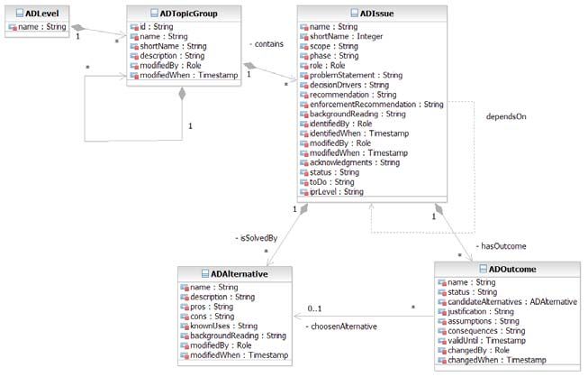
We distinguish decisions made and decisions required to facilitate reuse: An
ADIssue instance informs the architect that a single architecture design problem
has to be solved. ADAlternative instances then present possible solutions to this
problem. ADOutcome instances record an actual decision made to solve the prob-
lem including its rationale. Closely related ADIssues are grouped into AD-
TopicGroups, which form a hierarchy. Dependencies between ADIssues are mod-
eled as a dependsOn association; in [29], we define more dependency relations.
The metamodel is shown in the following figure:12 12 Industrial Case Study: Architectural Knowledge in an SOA Infrastructure
Reference Architecture
Figure 2. SOAD metamodel (source: [29])
ADIssue and ADAlternative provide reusable, project-independent background
information about decisions required: The problemStatement characterizes an
ADIssue on an introductory level, while backgroundReading and knownUses
point to further information. The decisionDrivers attribute states types of NFRs,
including software quality attributes and environmental constraints such as budget
and skill availability; the patterns community uses the term forces synonymously.
The role and phase attributes serve as a link to methods such as UMF. A recom-
mendation attribute conveys subjective information, which may be a simple rule
of thumb (“best practice”), a weighted mapping of forces to alternatives, or a
pointer to a more complex analysis process to be performed outside the decision
model. The recommendation should refer to decision drivers and pros and cons of
alternatives. With the backgroundReading attribute, supporting material such as
primers and tutorials can be referenced.
ADOutcome instances capture project-specific knowledge about decisions
made: The justification information refers to actual requirements (“sub-second re-
sponse time in customer interface”), as opposed to the ADIssue-level decision
drivers which only list types of requirements (“performance, i.e., response time
and throughput”). These two aspects of the knowledge have different reuse char-
acteristics: the ADIssue information has even more reuse potential then the pro-
ject-specific ADOutcome rationale. A second reason for factoring out ADOut-
come as a separate entity is that the same ADIssue might pertain to many elements
in a design model, e.g., business processes and service operations in SOA. There-
fore, types of logical and physical design model elements are referenced via the
scope attribute in the ADIssue. ADOutcome instances then are created dynami-
cally on projects, and can refer to design model element instances via their name.12.2 A SOA Infrastructure Reference Architecture 13 To give an example, a business process model might state that three “customer enquiry”, “claim check”, and “risk assessment” business processes have to be im- plemented in an insurance industry case. One ADIssue is to select an INTEGRATION TECHNOLOGY to let the business activities in each of the three busi- ness processes interact with other systems, with ADAlternatives such as WEB SERVICES and RESTFUL INTEGRATION. Problem statement (“Which technology should be used to let the business activities in the business process communicate with Web services and legacy systems?”) and decision drivers (“interoperability”, “reliability”, and “tool support”) are the same for all three business processes. Hence, it is sufficient to create a single ADIssue instance which has a “business process” scope. This value refers to a SOA-specific type of design model element. Project-specific decision outcome information such as the chosen alternative and its justification depends on the individual requirements of each process, e.g., “for customer enquiry, we decide for WEB SERVICES as Java and C# components have to be integrated in an interoperable and reliable manner, and we value the available tool support” and “for risk assessment, we select RESTFUL INTEGRATION because not all of the involved backend systems provide a SOAP message interface described by a WSDL contract”. Hence, three ADOutcome in- stances are created and associated with the same ADIssue. These instances capture the process-specific decision and its rationale. They refer to the actual business processes in their name attributes (“customer enquiry”, “claim check”, and “risk assessment”). Content. The RADM for SOA is organized into levels and layers: An overarching executive level comprises issues regarding requirements analysis and technical de- cisions of strategic relevance. A conceptual level, a technology level and a vendor asset level follow [29]. Architectural layers further structure the RADM. The next figure shows the resulting model structure (each box represents an ADTopicGroup comprising ADIssues dealing with the same topic area on one refinement level):
14 12 Industrial Case Study: Architectural Knowledge in an SOA Infrastructure
Reference Architecture
Executive Level
                         Application Architecture                                          Infrastructure Architecture             Example

                 Business                                                                Executive
               Requirements                                                              Decisions                   e.g. Platform Preferences
                 Decisions

Conceptual Level

                                                      Integration Layer
                                    Consumer Layer

                                                                            QoS Layer
                                     Process Layer
                Logical VP:                                                                          Physical VP:
                Conceptual           Service Layer                                                   Conceptual     e.g. Message Exchange Pattern
                 Decisions                                                                            Decisions
                                    Component Layer
                                     Resource Layer

Technology Level

                                                        Integration Layer
                                     Consumer Layer

                                                                             QoS Layer
                                     Process Layer
                Logical VP:                                                                          Physical VP:
                Technology            Service Layer                                                  Technology          e.g. Transport Protocol
                 Decisions                                                                            Decisions
                                    Component Layer
                                     Resource Layer

Vendor Asset                        Consumer Layer     Integration Layer
Level
                                     Process Layer                          QoS Layer
                Logical VP:                                                                          Physical VP:
               Vendor/Asset           Service Layer                                                  Vendor/Asset    e.g. DataPower Configuration
                 Decisions                                                                            Decisions
                                    Component Layer
                                     Resource Layer
                                                                                                                                       VP – Viewpoint

                      Figure 3. Layers and levels in RADM for SOA (source: [29])
   The same top-level topic groups are defined on the conceptual, the technology,
and the vendor asset level. The level and topic group hierarchy serves as a table of
decision model content. The hierarchical structure is motivated by our observation
that the technical discussions during SOA design often circle around detailed fea-
tures of certain vendor products, or the pros and cons of specific technologies,
whereas many highly important strategic decisions and conceptual concerns tend
to be underemphasized. These discussions are related, but should not be merged
into one; they reside on different refinement levels. Separating design concerns in
such a way is good practice; e.g., RUP with its elaboration points recommends a
similar incremental approach for UML class diagrams used as design models. We
adopted this recommendation for decision models and made the three refinement
levels explicit in the RADM for SOA.
   There are topic groups for seven logical SOA layers, consumer, process, ser-
vice, component, resource, integration, and QoS layer, which are introduced in
[1]. Two topic groups on each level contain issues pertaining to the logical and
physical viewpoint that can not be assigned to any layer. The model can be tai-
lored and irrelevant parts removed, e.g., if only issues dealing with processes, but
not issues dealing with ESB integration are of interest in a particular project con-
text. About a dozen subject area keywords are defined and expressed as topic tags,
e.g., “session management”, “transaction management”, “workflow”, and “error
handling”.
   The next figure is an excerpt of an ADIssue description in the RADM for SOA:
12.2 A SOA Infrastructure Reference Architecture 15
Architectural Decision (AD) Issue
Identified in: Enforced by:
Scope: Role: Phase:
Service WSDL, XSD
Service Operation Service Modeler Macro Design
Model Contracts
Decision drivers: Parameter understandability; ease of use and reuse; maintainability;
capabilities of BPEL, SOAP, WSDL, XML processors and interoperability; network
topology; number of deployment artifacts and generated code structure
ADIssue:
XML
ADIssue name: Msg-03, InMessageGranularity (Conceptual Level) Profiling
ADIssue: Problem Statement: How many message parts should be defined in the service contract?
Business How deep should the part elements be structured?
Granularity
Background Reading: No published patterns available yet that we could reference here.
ADIssue:
Out Message
ADAlternative 1: ADAlternative 2: ADAlternative 3: ADAlternative 4: Granularity
ADIssue: Dot pattern Bar pattern Dotted line pattern Comb pattern
Service
Type Single scalar Single complex Multiple scalar Multiple complex
parameter parameter parameters parameters ADIssue:
Operation
Easy to process for Deep structure and Handled by all Combination of To Service
SOAP/XML exotic types can common engines, options 2 and 3, Grouping
ADIssue: engines, much cause some programmer biggest overhead
Enterprise work for interoperability convenience. for processing
Data Model programmer issues. engines.
Recommendation: All alternatives have their place, depending on the decision drivers. ADIssue:
Base decision on layer and service type. Avoid overly deep nesting of data structures WDSL, XSD
unless you want to stress test the XML processing. Minimize message verbosity. Editor
Selection
Figure 4. Sample issue and alternatives in SOAI RA
The issue deals with the INMESSAGEGRANULARITY of a service operation. This
issue qualifies as a an architectural decision to be included in the RADM for SOA,
as its outcome has a significant impact on the quality attributes of the SOA-based
system under construction and the issue recurs for each service operation.
In many cases, the ADAlternatives of an ADIssue in the RADM for SOA refer
to an already existing patterns, e.g., those documented by Buschmann et al. [2], by
Fowler [5], or by Hohpe and Woolf [7]. In this case, no patterns are available yet;
we plan to publish the descriptions of the issue and its pattern alternatives (DOT,
BAR, DOTTED LINE, and COMB) in the future.
At present, the RADM for SOA consists of 86 ADTopicGroups and 389 ADIs-
sues with about 2000 ADAlternatives. The knowledge base is still growing, now
at a slower pace than in the beginning of the project. While this growth could con-
tinue infinitely, we plan to freeze the knowledge engineering once the 500 most
relevant issues have been compiled. The knowledge base will still have to be re-
viewed periodically to ensure that the contained information remains up to date.
Issues and alternatives will become obsolete as technology evolves; new ones will
be required. The SOAD level and layer structure helps to organize these activities
and reduce the related effort; conceptual knowledge dates at a slower pace than
that on the technology and on the vendor asset level.
Tool. Architectural Decision Knowledge Wiki is a Web-based collaboration sys-
tem and application wiki which implements the SOAD metamodel as well as addi-
tional concepts. It supports about 70 uses cases. The tool is featured in [21, 29].16 12 Industrial Case Study: Architectural Knowledge in an SOA Infrastructure
Reference Architecture
12.2.3 Physical Viewpoint: Operational Model
Applications employing SOA as their architectural style require a reliable SOA in-
frastructure which complies with the corporate-level technology standards and
runs inside existing or new operating environments such as datacenters. The IT
organizations of enterprises must provide such SOA infrastructures.
SOA infrastructures must be able to support the development, deployment, and
management of service consumers and providers, and host SOA middleware such
as ESBs, business process orchestration engines, service registries, but also com-
ponents in application servers which implement service consumers and providers
in some programming language (e.g., BPEL, C#, or Java).
The OM in SOAI RA is positioned to rapidly design such SOA infrastructures,
and plan the capacities of the underlying hardware (i.e., server and network re-
sources). Examples of such hardware capacity aspects are CPU speed, main mem-
ory size, disk space, and network adapter capacity (throughput).
An OM may be defined for a particular IT system, designed to meet specific
functional and non-functional requirements. An example is a WebSphere Process
Server [10] environment required to support service composition (business proc-
ess choreography) in a Customer Relationship Management (CRM) solution. In
such a case, the specified OM (see previous section) defines all functional and
non-functional characteristics of the model elements, while the physical OM pro-
vides a detailed configuration and capacity plan, which serves as a blueprint for
the acquisition, installation, and subsequent maintenance of the infrastructure re-
sources (i.e., server hardware, network equipment, and middleware).
In a reference architecture context, an OM can describe a template of how
(parts of) an IT infrastructure may be constructed in order to satisfy some general-
ized set of functional and non-functional requirements. In this case, the OM leaves
placeholders, requiring tailoring and integration with other partial OMs to satisfy a
particular set of concrete requirements. The purpose of such a generalized OM
may be to support enterprise-wide standardization of all SOA infrastructure envi-
ronments (e.g., WebSphere Process Server). Such standardization simplifies pro-
curement, education, and systems management.
SOAI RA adopts the OM notation and terminology defined in the IBM Archi-
tecture Description Standard (ADS) [24] and the OM technique defined in IBM
UMF [4]. Hence, three perspectives are taken during the design of the OM in
SOAI RA, answering the following questions:
• Which network zones are given or required (e.g., locations, security zones
created by application gateways and transport-level firewalls)?
• Which hardware nodes appear in these network zones?
• Which presentation, execution, and data deployment units are deployed
on these nodes to host application and middleware components?
As motivated in the SOAI RA overview above, SOAI RA contains a conceptual
OM and a specified OM; the physical OM has to be developed on each project
adopting SOAI RA. Hence, SOAI RA provides zone, node, and deployment unit12.2 A SOA Infrastructure Reference Architecture 17
definitions at the conceptual level and details those by adding NFR and other in-
formation at the specified level.
The following figure is a screen caption of a UML class diagram in IBM Ra-
tional Software Modeler. The classes are annotated with a stereotype called
which indicates that they represent an OM concept. The
nodes host deployment units, which correspond to SOA infrastructure elements.
For instance, the “application server node” hosts a “service integration bus” unit.
Figure 5. OM to (SO)AD linkage in SOAI RA
The figure also shows that nodes in the conceptual OM are linked to SOAD is-
sues, which are made available via the Architectural Decision Knowledge Wiki
tool (as introduced in the SOAD overview in the pervious section). In the exam-
ple, the application server node in the conceptual OM has issues such as
COMPONENT CONTAINER ASSET and WEB SERVICES PROVIDER ASSET attached.
This link between OM elements and SOAD issues is a key feature in SOAI RA: It
uses the scope attribute defined in the SOAD metamodel introduced previously.
We follow the same approach to link logical components and related issues.
With this approach, we make architectural knowledge available in the tool the ar-
chitect works with during design; however, we do not model the rather rich issue
descriptions in the same UML model, but couple architecture elements and related
issues loosely to ensure flexibility and usability of the two parts of the architec-18 12 Industrial Case Study: Architectural Knowledge in an SOA Infrastructure Reference Architecture tural knowledge, logical CM and physical OM on the one hand (design artifacts) and architectural decision knowledge on the other hand (rationale). 12.2.4 Summary of Approach and Benefits The UMF artifacts in reference architectures represent the recommended architec- tural to-be model to begin with (and aim for) when delivering service projects. They codify many lessons learned and best practices from projects around the world. To harvest such lessons learned and best practices, project-specific deliver- ables get assessed for applicability, are quality assured, sanitized, and hardened into artifacts generally reusable in similar projects. In short, reference architec- tures are a way to make collective project experiences and knowledge explicit and available to a wide audience, i.e., all GTS practitioners. Reference architectures pave the way for the consistent development of differ- ent service products. SOAI RA is the reference architecture of the GTS middle- ware service product line; it makes service products combinable. This is important since client projects can become quite large and complex and often deploy more than a single service product. SOAI RA and other reference architectures not only make service products combinable, but also offer an integrative approach across IBM hardware, software, and services products: They simplify the end-to-end so- lution design by establishing modeling standards (e.g. naming conventions), which are also shared between presales and project delivery functions. GTS practitioners benefit from SOAI RA in several ways: First and foremost, they learn from experienced peers how to model a solution, how to create the arti- facts required by UMF, and how to design an SOA infrastructure properly (educa- tion use case). In this regard, a reference architecture codifies tribal knowledge. A reusable asset that meets the wants and needs of practitioners and is easy to adopt can increase productivity: In particular, SOAI RA aims to accelerate the early project activities, allowing practitioners to tailor the provided artifacts ac- cording to the client-specific requirements and project context they are confronted with. The more of the hard design and modeling problems have already been solved in a reusable, standardized fashion, the more time practitioners can spend with their clients to resolve the particularly relevant, case-specific design issues. Furthermore, reference architectures have a quality assurance effect: Best prac- tices from projects around the world are captured in the reference architecture. Moreover, SOAI RA improves collaboration both within GTS and across IBM lines of business: It facilitates the knowledge exchange between projects and within a community of practice by establishing a common vocabulary. Finally, the model-driven approach in SOAI RA opens the door to automation: Due to the standardization of target architecture, it becomes possible to generate parts of the code and deployment artifacts directly from the models. Having summarized the motivation, anatomy, and benefits of SOAI RA, let us now present how we harvested its architectural knowledge from projects. We will return to the benefits when presenting user feedback in the second next section.
12.3 Harvesting SOA Decision Knowledge from Projects       19

12.3       Harvesting SOA Decision Knowledge from Projects

In this section, we give an overview of the architectural knowledge engineering
activities we conducted to create the Reusable Architectural Decision Model
(RADM) for SOA used in SOAI RA. We also define a four-step process and re-
lated guidance to syndicate architectural decision knowledge from such projects.

12.3.1 Sources of Architectural Decision Knowledge

The first source of input for the RADM for SOA was personal project experience
[2526, 28]. As a second step, we factored in selected architectural knowledge from
projects technically led by peers, leveraging a company-wide SOA and Web ser-
vices practitioner community with more than 3500 members. We screened several
hundred architectural decisions from more than 30 projects from several geogra-
phies and industries. A third type of input was systematic literature screening, e.g.,
SOA and patterns books, technology introductions, and vendor documentation.
   Originally, we had employed an ad hoc approach to incorporating these sources
of input. This ad hoc approach to asset harvesting turned out to be more labor in-
tense than originally anticipated: We were tempted to fix quality problems straight
away, adding our own expertise prematurely. This approach did not scale and did
not produce a satisfying model. Hence, we switched to a systematic approach. It
consists of a basic four-step knowledge harvesting process and related decision
modeling guidance.

12.3.2 Architectural Knowledge Harvesting Process

To overcome the limitations of our original ad hoc approach, we followed four
knowledge harvesting steps. Figure 6 illustrates these four steps, which we call
Review, Integrate, Harden, and Align (RIHA):

           Review              Integrate            Harden              Align With
          Raw Input           Into RADM           New Content          Other Content

                 Figure 6. Four-step knowledge harvesting process (RIHA)
  These steps are characterized as follows:
     1.    In the review step, raw input from completed projects (decisions made)
           is screened. This has the objective to assess the relevance and quality of
           the input. ADIssue and ADAlternative instances for all decisions that are
           decided to be included in the RADM are created (see below).
     2.    In the integrate step, existing information in the raw input is copied into
           appropriate attributes defined in the SOAD metamodel (see below).
20 12 Industrial Case Study: Architectural Knowledge in an SOA Infrastructure
Reference Architecture
3. In the harden step, the issue is decomposed if necessary, e.g., if there is a
violation of the level structure because concepts, technology characteris-
tics, and product features are covered in a single ADIssue. Moreover, the
issue and alternative information is completed in this step, for example
with less obvious alternatives, missing pros and cons, additional decision
drivers, and additional decision dependencies. The contributing project
might have to be contacted to clarify certain aspects.
4. In the align step, the new model element is reviewed and edited for read-
ability and consistency with already existing parts of the model.
It is worth noting that it is possible to iterate and harvest knowledge incremen-
tally, although Figure 6 seems to suggest a linear process.
12.3.3 Guidance for the Four RIHA Process Steps
Review step. During the review step, two qualification criteria are applied to de-
cide whether an issue should be included in a RADM:
1. The first criterion is the reuse potential: Is a real architecture design prob-
lem described, does the raw input qualify as an architectural decision?
Does a candidate issue pertain to one of the principles and patterns defin-
ing SOA as an architectural style? Does it present real alternatives? Will it
recur, i.e., does it have sustainable, long lasting character or is it a tactical
or temporary decision? Does it avoid to reference proprietary features or
characteristics?
2. The second criterion is technical and editorial quality: Is the issue techni-
cally sound, particularly the justification for the chosen design? Did the
contributing project succeed? Does its description read well? Is established
terminology used, e.g., are the referenced design model elements defined
in the literature? Can issue and outcome be separated from each other?
A high reuse potential as indicated by the answers to the questions regarding
the first criterion is mandatory. If there are doubts about the technical quality of
the candidate issue, it is not used; the editorial quality can be improved with rea-
sonable editing effort if there is a strong need for the issue (e.g., high reuse poten-
tial). The contributing practitioner may be contacted in such a case to obtain addi-
tional information about the circumstances under which the decision was made.
Integrate, harden, and align steps. When integrating and hardening knowledge
that qualifies for inclusion in the RADM, the raw input is mapped to the SOAD
metamodel in the following way (transitioning from decisions made to decisions
required):
Table 1. ADM to RADM attribute mapping during asset harvesting
Knowledge Raw input RADM for SOA SOAD attributes and
type from project content further comments
Problem Outcome (often has an ADIssue Problem statement, back-12.3 Harvesting SOA Decision Knowledge from Projects 21
Knowledge Raw input RADM for SOA SOAD attributes and
type from project content further comments
embedded issue) ground references
Solution Chosen alternative ADAlternative Description, known uses
Rationale Justification ADIssue Recommendation
Rationale Justification ADIssue Decision drivers, pros and
cons of alternatives from
“because” sentence in justi-
fication
Requirements link Assumptions ADIssue Decision drivers
Dependencies Consequences, related Related decisions Dependency types in [29];
decisions often missing in raw input
Scoping Decision name, design ADIssue scope attribute
model references
Method linkage Timestamp, decision ADIssue phase, role attributes
maker
In [29], we define quality heuristics for architectural decision models, which
advise on the number of nesting levels and how to work with the logical and tem-
poral dependency relations defined in that paper. We now present several addi-
tional guidelines. All of these are suggestive rather than normative.
A meaningful name for the issue must be found. The patterns community ad-
vises us that finding good names is essential when creating a pattern language, but
also hard; the same holds for issue and alternative names. Names should be com-
pact, but expressive. They must be self-explaining, e.g., when appearing in a tool
that does not display any other attributes in a particular view. Names should be
generic so that they do not to have to be changed often, but also be expressive so
that they can serve as identifiers for issues and alternatives in the RADM. The en-
tire description of an issue and its alternatives should adopt the terminology estab-
lished by the principles and the patterns defining SOA as an architectural style.
All alternatives listed for an issue must solve the same problem. As a conse-
quence, all alternatives must reside on the same refinement level, e.g., conceptual
and technology alternatives are assigned to different (but related) issues. The al-
ternatives of an issue should be disjoint and unambiguous to make solutions com-
parable and support code generation as an additional form of decision enforcement
in an MDD context [27]. They should catch all known mainstream solutions as
well as a few exceptional ones that have been applied in practice. If a solution is
known under several names (e.g., façade and wrapper pattern), the alias names
should be listed in the description attribute. By convention, the alternatives are or-
dered from common and recommended to exceptional; if present, fallback alterna-
tives such as CUSTOM CODING or OTHER LANGUAGE appear last. The same order-
ing scheme should be applied consistently for all issues. A “good enough”
approach is followed; it is not a primary goal to be complete. The accuracy of the
knowledge has higher priority than its quantity.
The information about decision drivers should use a consistent vocabulary. An
established NFR or quality attribute taxonomy should be used. It may originate
from enterprise architecture guidelines [17] or an industry standard such as [11].
The more homogeneous and consistent the vocabulary is, the simpler it becomes
to tailor the model and to use it during the decision making. For instance, consis-You can also read