5G Semiconductor Solutions - Infrastructure and Fixed Wireless Access - JUNE 2018 - Qorvo
←
→
Page content transcription
If your browser does not render page correctly, please read the page content below

E-BOOK

5G Semiconductor Solutions -
Infrastructure and Fixed
Wireless Access
                                    JUNE 2018

     S P O N S O R E D   B Y

                     5G
                     SPEED
Table of Contents

3       Introduction
        Pat Hindle
        Microwave Journal, Editor

4       5G Update: Standards Emerge, Accelerating 5G Deployment
        Pasternack
        Irvine, Calif.

10      5G Fixed Wireless Access Array and RF Front-End Trade-Offs
        Bror Peterson and David Schnaufer
        Qorvo, Greensboro, N.C.

19      5G Is Coming: How T&M Manufacturers Can Prepare For
        and Benefit From 5G
        Randy Oltman
        Analog Devices Inc., Norwood, Mass.

22      Gallium Nitride – A Critical Technology for 5G
        David Schnaufer and Bror Peterson
        Qorvo

29      Pre-5G and 5G: Will The mmWave Link Work?
        Andreas Roessler
        Rohde & Schwarz, Munich, Germany

                                              2
Introduction

                         5G Semiconductor Evolution
         By 2023, there are 1 billion forecast subscriptions for 5G technology according to
Ericsson, CCS Insight. Recent forecasts have been increasing due to the early standards
release by the 3GPP and other positive market trends with announcements by leading U.S.
operators AT&T, Sprint and T-Mobile that promise mobile 5G services later this year or early
next year. In addition, Verizon will be launching fixed access 5G services this year.
         According to a recent 5G Americas release, Cisco forecast 25 million 5G-capable
devices and connections by 2021; analyst firm Ovum currently predicts 84 million by 2021;
CCS Insight increased their predictions by 50 percent (over their October 2017 forecast)
to 280 million 5G connections in 2021, with 60 million 5G connections expected in 2020.
Ovum expects 11 million 5G connections in 2020. By 2023, both CCS and Ericsson
forecast 1 billion 5G connections worldwide.
          With this much growth and activity for 5G networks, we have put together this
eBook covering some of the technical challenges and solutions for 5G infrastructure and
fixed wireless access design along with overviews of the market. We start with an overview
of the latest standards and trends related to radio components and then cover some of the
semiconductor design tradeoffs and architectures for 5G fixed wireless access mmWave
arrays. The next article discusses the advantages for semiconductor and measurement
companies to work together to overcome 5G challenges and how to prepare for them. Then
we provide a detailed look at how GaN technology can solve many of the 5G challenges
for infrastructure and fixed wireless access systems that require higher efficiency, broad
bandwidths, higher linearity and small size. The last article covers how mmWave links will
perform and how to properly characterize and measure them.
         We hope this eBook on 5G Semiconductor Solutions covering infrastructure
and fixed wireless access helps engineers understand the tradeoffs and measurements
needed to design better 5G solutions. A better understanding radio link characteristics and
semiconductor capabilities should result in better designs and reduce time to market.

Pat Hindle, Microwave Journal Editor

                                              3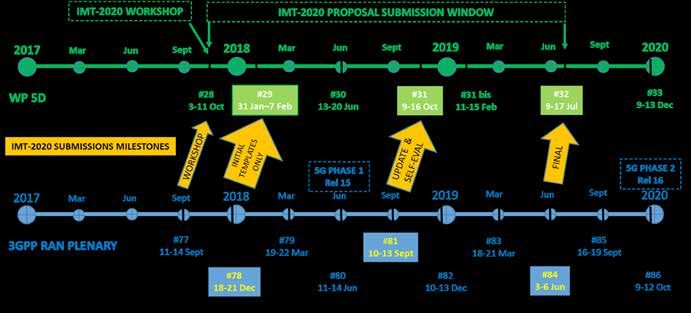
5G Update: Standards Emerge,
Accelerating 5G Deployment
Pasternack
Irvine, Calif.

5G technologies and standards have recently emerged from buzz and corporate blustering to
real and rapidly paced definitions and development. When 5G visions were first announced,
many considered the performance targets in these predictions to be pipe dreams. However,
corporate initiatives to develop 5G technology with real 5G radio and networking platforms
and international collaboration on 5G standards has proceeded at a pace few could predict. If
this progress means to meet performance targets for 5G, manufacturers must accelerate their
timetables and their supply chains to meet the demands of new and competitive 5G hardware
and systems.

                   T
                             he race to capture the global busi-    EARLY 5G FEATURES AND USE CASES
                             ness for upcoming 5G solutions—           Though the expected features and use
                             consumer, commercial and gov-          cases for 5G are diverse and extensive,
                             ernment—is starting to resemble        the start of the 5G rollout will likely ad-
                   the historic space race between Russia and       dress only a few of the featured use cas-
                   the U.S. The major difference is this goes far   es: enhanced mobile broadband (eMBB),
                   beyond a race between two sovereign su-          ultra-reliable low latency communications
                   perpowers, with many international compa-        (URLLC) and massive Internet of Things
                   nies and countries in the competition. True      (mIoT) or massive machine-type communi-
                   5G solutions require many layers of national     cations (mMTC), as illustrated in Figure 1.
                   and international regulation, as well. Major     These provide increased throughput and
                   international telecommunications compa-          performance for user equipment (UE), while
                   nies and manufacturers are all competing to      offering a mobile network designed to sup-
                   demonstrate 5G capabilities and features,        port the massive number of new IoT, or In-
                   while simultaneously paving the way for vi-      dustry 4.0, applications. Interestingly, these
                   able mmWave radio access unit and radio          early 5G features will likely be implemented
                   access network (RAN) technology. With            at sub-6 GHz frequencies (current cellular
                   spectrum, radio and network standards so-        bands, ≤ 1, 3.5 and 3.7 to 4.2 GHz and vari-
                   lidifying ahead of schedule, the pioneering      ous combinations based on country) before
                   aspects of 5G—mainly the expansion into          2020, offering opportunities in the vehicle
                   many more verticals or slices than mobile        and broadcast market, infrastructure and,
                   broadband—are gaining focus and invest-          primarily, mobile.
                   ment.
                                     WWW.MWJOURNAL.COM/ARTICLES/30263
                                                      4
vices now, there is a general impetus to hurry along the
                            eMBB                                               advent of 5G. With so many companies and countries
                 Enhanced Mobile Broadband                                     taking the initiative with announcements of 5G deploy-
                          10 Gbps                                              ments, these industry and international consortiums
                                                                               have been moving quickly with specifications, stan-
                                                                               dards and spectrum allocation.
                                    3D Video UHD Screen
                                                                                  Referencing the Verizon 5G Technical Forum (V5GTF),
                                        Work and Play in the Cloud             companies feeling the pressure to commercialize more
         Smart                                                                 rapidly are even creating new forums to accelerate the
      Home/Building                          Augmented Reality
                                                                               development of 5G technologies. Another example of
                                               Industry Automation             carrier-led efforts to advance 5G is the merger of the
                                                                               xRAN forum and C-RAN Alliance, with the focus of
   Smart City                                        Mission Critical          evolving RAN technology from hardware-defined to vir-
                                                      Applications
                                                                               tualized and software-driven. Industry forums in market
                            Future IMT                  Self-Driving           verticals other than mobile are also forming to accel-
                                                            Cars               erate adoption and standardization. For example, the
                                                                               5G Automotive Association encourages collaboration
        mMTC                                   uRLLC                           among telecommunication and automotive companies.
    Massive Machine                        Ultra-Reliable and                     Some explanation for this rapid pace could be the
  Type Communications                         Low-Latency                      concern that collaboration-based organizations have
      1 million/km2                         Communications                     for early adopting companies and countries develop-
                                                  1 ms                         ing their own regional standards to meet the demand
s Fig. 1  The primary use cases for 5G. Source: Werner Mohr,                   ahead of the competition. For example, some compa-
The 5G Infrastructure Association.                                             nies, namely AT&T and Verizon, have already claimed
                                                                               they will provide 5G services in select cities in 2018.
EARLY 5G FACTORS AND INFLUENCERS                                               These 5G services will not necessarily meet all 3GPP 5G
   The main 5G standards bodies and organizations are                          specifications, but will likely provide superior through-
consistent with past generations of mobile wireless, i.e.,                     put to current 4G services and be readily upgraded,
3GPP, GSMA, ITU and each country’s spectrum regula-                            most likely through software, to the final 5G specifica-
tory agency. Importantly, the heads of industry-leading                        tions. Without 5G capable handsets, either sub-6 GHz
companies are driving these organizations’ focus and                           or mmWave, it is likely that these companies will offer
standards developments. Other industry consortiums                             either hotspot or fixed wireless access (FWA) services
and alliances, such as the Next Generation Mobile Net-                         instead.1-2 While the UE may not yet be available, 5G
works (NGMN) alliance and TM Forum, are also contrib-                          base station and terminal equipment is; Huawei recent-
uting and advising in the development of 5G standards                          ly announced 5G end-to-end solutions.3 These offer
and specifications.                                                            sub-3 GHz, C-Band and mmWave operation with mas-
   With the forecast increase in competition for 5G                            sive MIMO technology and are reportedly fully 3GPP
services, and the need to provide lower cost data ser-                         5G compliant. In a demonstration with Telus in Canada,

                              E2E Management Plane             Slicing Management       Resource Management

                              Enable Plane           Network Service Enabler        Complex Event Process         Analytics

                                                                                                       Unified Database       Policy Data

                                       RAN Non-Real Time                                        Composable Control Function (CP)
           LTE                                                                                   Service       User
                                                                                                               Data      MM       SM        Service
                                cRRC          cRRM          AC                                    Ctrl
           RAN      Wi-Fi                                                                                                        Control Plane Service
           Real Time                                                      SDN                                                    Service Component
                              Multi-RAT
                                              GW-U       Application    Controller
                             Access Mgmt                                                                   Security Mgmt Policy Mgmt   Component
           5G                                                                                                             eGTP
                              Mobile Cloud Engine (MCE)                                         Programmable Data Forwarding (UP)
                                                                                                   GW-U       GW-U          GW-U            GW-U
                                        CloudRAN
                                                                                                  Service Oriented Core (SOC)

s Fig. 2  A new virtualized cloud radio access network architecture will enable operators to serve the multiple use cases envisioned
for 5G. Source: Huawei.
                                                                         5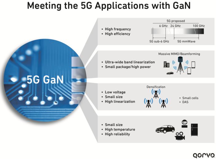
a 5G wireless to the home trial using Huawei equipment              FR1 NR bands is 100 MHz, of which only n41, n50, n77,
reportedly demonstrated 2 Gbps, single-user down-                   n78 and n79 are capable. These bands are also designat-
load speeds.4                                                       ed as time-division duplex (TDD) bands, for which carrier
   With a lack of a standardized infrastructure in market           aggregation (CA) should enable greater than 100 MHz
verticals other than mobile wireless, however, the stan-            functional bandwidth.
dardization and specification for vehicle and industrial                Also in this release are the descriptions of new RAN
applications may take far longer than anticipated. This             architecture options. The new architecture is built
could explain, somewhat, the additional focus of tele-              around a network virtualization strategy, where the con-
communication service providers on 5G applications                  trol and user planes are separated. Referred to as net-
in the broadcast and home internet services markets.                work function virtualization (NFV) and software-defined
FWA using sub-6 GHz and mmWave 5G capabilities                      networking (SDN), these features are designed to en-
could provide gigabit internet speeds to homes without              able future network flexibility and a variety of applica-
expensive fiber installation and even undercut the cable            tions. This methodology is meant to continue providing
television and home phone service giants.                           enhanced mobile telecommunications, while adding
                                                                    diversity of services—hence, independent network slic-
5G STANDARDS AND SPECIFICATIONS                                     ing.9
   The GSMA recently released a report, “Mobile Econ-                   Future 5G “Cloud RAN” capabilities (see Figure 2)
omy,” which claims that two-thirds of the world’s mobile            are meant to support multiple RANs, standards and op-
connections will be running on 4G and 5G services by                erators using the same physical infrastructure or core
2025, with 4G accounting for over half of the global                network. Such an adaptable RAN would allow for vari-
connections and 5G accounting for approximately 14                  ous applications and industries to rely on the same hard-
percent.5 Not surprisingly, the demand has caused stan-             ware and network assets, physical infrastructure to pave
dards and specification organizations to step up their              the way for future opportunities. The system to provide
timetables, and market pressures are solidifying 5G ra-             capabilities for service-level agreements for a collection
dio specifications earlier than expected.6 However, the             of devices is dubbed “network slicing” by 3GPP.
“5G precursor” specifications being released now are                    The future 5G standard, what will be concluded in
not the finalized 5G specifications and standards, rather           the complete 3GPP Release 15, or 5G Phase 1, will be
evolutionary steps from 4G specifications that will be              finalized in June 2018 (see Figure 3). Before the end of
compatible with the future 5G specifications.                       2019, 3GPP will provide updates to Release 15, and a
   The latest 3GPP specification defines the non-stand-             clearer vision of Release 16, or 5G Phase 2, will become
alone 5G new radio (NSA 5G NR),7 which requires an LTE              available in December 2019. Currently, there is little in-
anchor and 5G NR cell. The LTE anchor provides the con-             formation on how 5G rollouts will occur and what indus-
trol plane and control plane communications, while the              tries, outside of mobile wireless, will begin adopting the
5G NR will provide enhanced data capacity. The NSA 5G               capabilities of 5G. Though trials have been performed
NR specification currently only covers frequency range 1            and early 5G network and radio access hardware is
(FR1), between 450 and 6000 MHz. These bands are des-               available, UEs have yet to be released, and operators
ignated in Table 5.2-1 in the 3GPP specification document           have virtually no experience and limited understanding
38101-1,8 and are subject to modification when Release              or expectations of 5G. Furthermore, mmWave hard-
15 is issued in June 2018. The maximum bandwidth for                ware is not yet widely available and, without this valu-

s Fig. 3   3GPP timeline for 5G specifications. Source: 3GPP.
                                                                6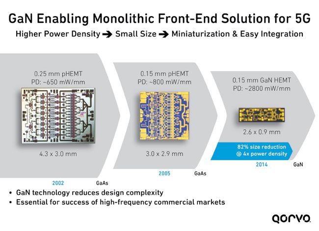
able experience, solidifying 5G mmWave specifications             UEs. Also, FWA 5G modems and transceiver chips can
is impractical. The mmWave frequency designations for             be larger, use more power and cost more than modem
5G will not be identified for the ITU until WRC-2019, in          and transceiver chips for UE.
time for IMT-2020.                                                    Available 5G modems, typically with integrated 5G
    5G Phase 1 is still based on OFDM waveforms, though           transceivers, are offered by Samsung, Qualcomm, Intel,
there are a variety of candidate waveforms which may              Huawei and others. Some of these early 5G chipsets are
eventually supersede OFDM. Specifically, 5G phase 1               reportedly capable of 2 Gbps data rates and mmWave
leverages cyclic prefix OFDM (CP-OFDM) for the down-              transceiver operation at 28 GHz. Common features in-
link, and both CP-OFDM and discrete Fourier transform             clude NSA 5G NR compatibility, with a variety of beam-
spread OFDM-based (DFT-S-OFDM) waveforms for the                  forming techniques, antenna switching, 3D frequency
uplink. 5G Phase 1 allows for flexible subcarrier spac-           planning tools and virtualized RAN.13-14
ing, where the subcarriers can be spaced at 15 kHz ×                  Currently, device and network hardware manufactur-
2n to a maximum of 240 kHz with a 400 MHz carrier                 ers, with associated telecommunications service pro-
bandwidth. Up to two uplink and four downlink carriers            viders and test and measurement manufacturers, are
can be used, for a combined uplink bandwidth of 200               engaging in 5G NR trials with simulated UEs. Samsung
MHz and downlink bandwidth of 400 MHz.                            and National Instruments, as well as Datang Mobile and
                                                                  Keysight Technologies, demonstrated what will likely
CURRENT 5G HARDWARE                                               be commercial 5G base station hardware and 5G UE
    For the past few years, many telcos and hardware/             emulation systems at Mobile World Congress 2018.15-16
platform manufacturers have been engaging in a game               It is likely that 5G UE chipsets will become available in
of 5G one-upmanship. Early demonstrations included                2019, although it is unknown if these UE will leverage
mmWave throughput, mMIMO, CA and a variety of                     mmWave technology or just the sub-6 GHz 5G FR1 fre-
software and hardware examples. Many of the latest 5G             quencies.
trials and demonstrations involved technology more                    The latest commercially available 5G hardware so-
aligned with the upcoming 3GPP Release 15, capable                lutions are typically RF front-end (RFFE) modules de-
of being updated by software to meet the final 5G                 signed to account for the new NSA 5G NR frequencies,
Phase 1 specification and future updates.                         which can be included with other RFFE hardware to
    Hence, many of the recently released and announced            offer a complete solution. These RFFEs include pow-
5G modems and transceivers are able to be updated                 er amplifiers (PA), low noise amplifiers (LNA), switches
via software, and offer throughput handling capabilities          and filters and differ somewhat from 4G RFFEs. As the
that account for greater bandwidth availability at cur-           power Class 2 specification for higher output power (26
rently unavailable mmWave frequencies. Many leading               dBm at the antenna) is available for 5G hardware, PAs
hardware manufacturers and telecommunication com-                 may be higher power than with 4G, necessary to over-
panies are continuing to push to advance 5G trials and            come increased propagation losses at higher frequen-
deployments by 2019, well ahead of a final specifica-             cies through the atmosphere and common building
tion, by leveraging NSA 5G NR and technology that                 materials.
can be modified to meet the finalized specifications.10               With 100 MHz of available Tx bandwidth, techniques
Given the nature of the race to commercialize 5G, and             like envelope tracking—which currently only supports
the likelihood of future 5G specifications adjusting to           up to 40 MHz of bandwidth—may not be viable; less ef-
the findings of early trials and deployments, program-            ficient techniques, such as average power tracking are
mability and flexibility of both the software and hard-           more likely for early 5G systems. These early 5G RFFE
ware of 5G radios and core networks are essential.                modules will likely be wideband, requiring additional
    Another factor to consider with 5G hardware is not            filtering for the new sub-6 GHz 5G bands, as well as the
only backward compatibility, but dual connectivity of             legacy and still necessary 4G bands. These multi-band
4G LTE and 5G systems. Similar to how prior genera-               filters are currently more complex combinations of sur-
tions of mobile wireless were eventually integrated into          face acoustic wave (SAW), bulk acoustic wave (BAW)
the latest specifications, it is likely that current 4G LTE       and film bulk acoustic wave (FBAR) filter banks and in-
rollouts will be merged into future 5G specifications.            tegrated modules.
Supporting dual connectivity, backward compatibility
and future 5G specifications will require highly adapt-           RF HARDWARE AND TEST SYSTEMS
able RF hardware that can allocate resources based on                Given the inclusion of new sub-6 GHz frequency
the actual environment, not just preprogrammed sce-               bands in NSA 5G NR, new RF hardware is needed to sup-
narios.11-12                                                      port these new frequencies—specifically n77, n78 and
    As the finalized 5G mmWave spectrum and radio                 n79—which were not previously used for mobile wire-
hardware is not yet determined, and extensive mobility            less. Though not determined in NSA 5G NR, frequency
trials with mmWave frequencies are still underway, the            bands below 600 MHz may eventually be supported by
first round of 5G mmWave technology will provide fixed            5G for massive low power connectivity such as IoT, In-
wireless service (FWA). This approach minimizes many              dustry 4.0/Industrial IoT and other machine-type com-
of the challenges associated with a complete 5G solu-             munications. The additional subcarrier channel spacing,
tion, including mmWave mobility concerns around non-              bandwidth, CA and 4 x 4 MIMO specifications result in
line-of-sight and antenna beam tracking with moving               the need for large numbers of filters, antennas, LNAs,

                                                              7
uplink, meaning six independent RF pathways. 5G an-
Drone tenna tuning technologies will be critical to maximize
Communications
Private IoT
Networks antenna radiation efficiency over wide bandwidths.
These RF pathways must also be much wider than 4G
5G NR LTE pathways, as NSA 5G NR now supports 100 MHz
Public mmWave LTE IoT
Safety/
Emergency
bandwidth on a single carrier, with more CA options
Services 5G NR Sub-6 GHz (up to 600 new combinations with Release 15). NSA 5G
Automotive Existing LTE
NR also allows for 200 MHz combined uplink and 400
LTE IoT LTE
(C-V2X) Deployments
MHz combined downlink bandwidth. This results in a
substantial amount of data to process, challenging for
energy efficient UEs and base stations.
s Fig. 4 Once deployed, standalone 5G services, operating at It is probable that the RF hardware for UEs will be
sub-6 GHz and mmWave frequencies, will need to coexist with increasingly integrated, with filter banks, high density
LTE. Source: AndroidAuthority.com; used with permission.
switches, antenna tuning, LNAs and PAs integrated into
PAs and switches, with accompanying NSA 5G NR mo- RFFEs with systems on chip (SoC) technologies. 5G UE
dems and RF transceivers. antennas may also be integrated solutions, possibly with
The early 5G modems and transceivers do not nec- antenna tuning and some pre-filtering and beamform-
essarily need to contend with these challenges, as ing features included. This level of integration is also
these commercial devices can operate on select bands. plausible to achieve the cost targets to ensure handsets
However, 5G base stations for eMBB and future indus- are affordable and meet phone form factors.17-19 With
trial and vehicle applications will require forward and the increased complexity of 5G and the need for dense
backward compatibility. This means that 5G RF hard- RF solutions, it is no surprise that many UE manufactur-
ware will need to service all current mobile frequency ers are attracted to 5G modem-to-antenna solutions for
bands, as well as 5G FR1 and 5G mmWave FR2 fre- faster development and deployment.
quencies (see Figure 4). This is a particularly trouble- Many current 4G UEs and base stations rely on LD-
some hardware challenge, as the hardware for many of MOS, GaAs and SiGe PAs, with GaN a recent entry
the existing cellular frequencies may interfere with the into the base station PA market. As the frequency is ex-
NSA 5G NR bands, as dual connectivity is necessary to tended to sub-6 GHz, LDMOS, which struggle beyond 3
meet the throughput specifications. Also, the new NSA GHz, is less likely to meet 5G specifications, while GaN
5G NR frequency bands surround the ISM bands for Wi- PAs—and possibly LNAs—are likely to be used in the in-
Fi, Bluetooth and other wireless equipment operating frastructure. GaAs and SiGe amplifiers will compete for
in the unlicensed bands. amplifier and switching functions in the sub-6 GHz 5G
With such closely packed bands and extremely wide- applications. To maintain lower cost and smaller form
band radios, the performance degradation from re- factors than current mmWave PA, LNA and switch solu-
ceiver desensitization is likely with inadequate filtering, tions provide, highly integrated RF silicon on insulator
PA linearity and harmonic suppression. New NSA 5G (SOI) technologies are likely to be used for 5G mmWave
NR transmitters can operate with higher output power applications. Future RFFEs may use RF SOI, SiGe BiC-
and higher peak-to-average power ratios for maximum MOS or RF CMOS SoCs that integrate the PA, LNA,
throughput, which may cause problems with co-located switches and control functions to operate mmWave
5G receivers in the same base station or nearby 5G de- phased array beamforming antenna systems (see Fig-
vices. ure 5). It is possible that future RF silicon technolo-
Real estate for RF hardware, especially antennas, is gies can be further integrated or combined with other
already small in UEs, and 5G specifications may require technologies to include filtering and the digital hard-
4 x 4 MIMO for the downlink and 2 x 2 MIMO for the ware required to enable hybrid beamforming modules.
Future variations of RF SOI or RF CMOS may even be
integrated with more advanced digi-
Quadplexer PMU LDO Phase Shifter 1 Diplexer 1 tal hardware, such as FPGAs, memory
Antenna Array
PA 1 and processors. Baseband processing
Radio Control 1st Stage
ET
and accessory DSP functions could be
Conversion LNA 1 implemented in the package, as well,
TX-IF
for compact 5G mmWave solutions.
As frequency routing and filtering is
fL01=
essential for 5G CA and back compat-
• • •
• • •
• • •
LO • • •
23.2 to 23.8
GHz ibility with prior mobile generations,
integrated SAW, BAW, FBAR and other
RX-IF Phase Shifter 8 Diplexer 8 integrated resonators and filter tech-
PA 8
ET
nologies are essential for UEs and even
Power / DC / Reference
LNA 8
compact small cells. With the poten-
Temp Control tial for interference and design com-
RSSI RSSI Control
plexity, 5G modules for UEs will also
likely incorporate Wi-Fi and Bluetooth
s Fig. 5 5G FDD beamforming module architecture. Source: arXiv:1704.02540v3 [cs.IT].
8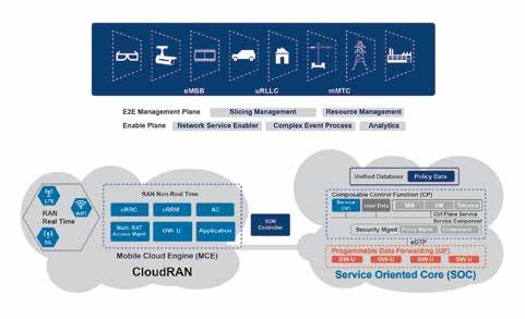
modules, further increasing the filtering and frequency                     14.		“Intel Introduces Portfolio of Commercial 5G New Radio Modems,
routing complexity. Other integration-capable technolo-                           Extends LTE Roadmap with Intel XMM 7660 Modem,” Intel, Novem-
                                                                                  ber 2017, https://newsroom.intel.com/news/intel-introduces-portfo-
gies, such as RF SOI, may be employed for 5G RFFEs,                               lio-new-commercial-5g-new-radio-modem-family/.
as recent advances in RF SOI enable filter and amplifier                    15.		 “NI and Samsung Collaborate on 5G New Radio Interoperability De-
co-integration. It may be several years before SOI filters                        vice Testing for 28 GHz,” National Instruments, February 2018, www.
are used for sub-6 GHz 5G applications, although it may                           ni.com/newsroom/release/ni-and-samsung-collaborate-on-5g-new-
                                                                                  radio-interoperability-device-testing-for-28-ghz/en/.
be sooner for mmWave systems, as amplifier and switch                       16.		“Keysight Technologies, DatangMobile Demonstrate 5G-New Ra-
integration possible with SOI technologies make this an                           dio Solutions at Mobile World Congress 2018,” Keysight Technolo-
attractive next step.                                                             gies, February 2018, https://about.keysight.com/en/newsroom/
                                                                                  pr/2018/27feb-nr18025.shtml.
                                                                            17.		 Y. Huo, X. Dong and W. Xu, “5G Cellular User Equipment: From The-
CONCLUSION                                                                        ory to Practical Hardware Design,” IEEE Access, Vol. 5, July 2017, pp.
   The rapid progression of 5G specifications and the                             13992-14010.
rush of mobile wireless manufacturers and service pro-                      18.		 “Qorvo® and National Instruments Demonstrate First 5G RF Front-
                                                                                  End Module,” Qorvo, February 2018, www.qorvo.com/newsroom/
viders to start 5G trials and deployments has led to a                            news/2018/qorvo-and-national-instruments-demonstrate-first-5g-rf-
plethora of early 5G demonstrations and interim 5G                                front-end-module.
specifications. In just the past few months, modem,                         19.		 P. Moorhead, “Qualcomm Raises Wireless Stakes With Full 5G Mod-
transceiver and RF hardware manufacturers have been                               ules and More RF Offerings,” Forbes, February 2018, www.forbes.
                                                                                  com/sites/patrickmoorhead/2018/02/27/qualcomm-raises-wireless-
announcing 3GPP-compliant 5G solutions, which rely                                stakes-with-full-5g-modules-and-more-rf-offerings/#d192567ae9f2.
on heavy integration and software reprogrammability                         20.		“Frost & Sullivan Spots Five Areas in Radio Frequency Test & Mea-
to meet current demand and provide future-proofing.                               surement that Will Create Over $30 Billion in New Revenues by
This deep level of integration and soon-to-come 5G                                2023,” Frost & Sullivan, February 2018, ww2.frost.com/news/press-
                                                                                  releases/frost-sullivan-spots-five-areas-radio-frequency-test-mea-
deployments will require flexible test and measurement                            surement-will-create-over-30-billion-new-revenues-2023/.
systems which can be readily adapted to the changing
standards and lessons learned from early trials.20 Ac-
cess to 5G accessories and interconnect technologies,
especially 28 GHz and other mmWave components and
devices, will be essential to prevent delays in trials and
deployments.■                                                                     Anokiwave 5G Phased Array
References
1.		S. Segan, “What is 5G,” PCMag, March 2018, www.pcmag.com/ar-
     ticle/345387/what-is-5g.
2.		“Paving the Way for Wireless Internet TV to the Home,” RCR
     Wireless News and Anritsu, February 2018, www.rcrwireless.
     com/20180222/5g/paving-way-wireless-internet-tv-home.
3.		“Huawei Launches Full Range of 5G End-to-End Product Solu-
     tions,” Huawei, February 2018, www.huawei.com/en/press-events/
     news/2018/2/Huawei-Launches-Full-Range-of-5G-End-to-End-Prod-
                                                                                 AWMF-0156 39 GHz                        AWMF-0135
     uct-Solutions.                                                               Silicon 5G Tx/Rx                     26 GHz Silicon 5G
                                                                                   Quad Core IC                        Tx/Rx Quad Core
4.		J. P. Tomás, “Huawei, Telus Launch 5G Fixed Wireless Trial in
     Canada,” RCR Wireless News, February 2018, www.rcrwireless.
     com/20180215/5g/huawei-telus-5g-fixed-wireless-tag23.
5.		“Two-Thirds of Mobile Connections Running on 4G/5G Networks
                                                                                       (Sedona)                            IC (Thor)
     by 2025, Finds New GSMA Study,” GSMA, February 2018, www.
     gsma.com/newsroom/press-release/two-thirds-mobile-connections-
     running-4g-5g-networks-2025-finds-new-gsma-study/.
                                                                                   The AWMF-0135/0156 is a highly inte-
6.		”Video — NR First Specs & 5G System Progress,” 3GPP, January                 grated silicon quad core IC intended for 5G
     2018, www.3gpp.org/news-events/3gpp-news/1934-nr_verticals.
7.		“3GPP Specification Series,” 3GPP, www.3gpp.org/DynaReport/38-                phased array applications that supports 4
8.
     series.htm.
     “Specification    #:   38.101-1,”     3GPP,     https://portal.3gpp.
                                                                                 radiating elements, including phase & gain
     org/desktopmodules/Specifications/SpecificationDetails.                      control for analog RF beam steering, and
     aspx?specificationId=3283.
9.		“Video Interview — On 5G Core Stage 3 Work,” 3GPP, January                   operates in half duplex fashion to enable a
     2018, www.3gpp.org/news-events/3gpp-news/1940-ct_5g.                                       single antenna.
10.		“Global Mobile Industry Leaders Commit to Accelerate 5G NR for
     Large-Scale Trials and Deployments,” Qualcomm, February 2017,                               Learn More
     www.qualcomm.com/news/releases/2017/02/25/global-mobile-
     industry-leaders-commit-accelerate-5g-nr-large-scale-trials.
11.		B. Thomas, “Is Your Handset RF Ready for 5G?,” Qorvo, February
     2018, www.qorvo.com/resources/d/is-your-handset-ready-for-5G-
     qorvo-white-paper.
12.		“Making 5G NR a Commercial Reality; A Unified, More Capable
     5G Interface,” Qualcomm, December 2017, www.qualcomm.com/
     documents/accelerating-5g-new-radio-nr-enhanced-mobile-broad-
     band-and-beyond.
13.		“Samsung Unveils the World’s First 5G FWA Commer-
     cial Solutions at MWC 2018,” Samsung, February 2018,
     https://news.samsung.com/global/samsung-unveils-the-worlds-
     first-5g-fwa-commercial-solutions-at-mwc-2018.

                                                                       9
5G
                                                                                       Editor’s Note: At the end of December, the 3GPP approved
                                                                                       the 5G non-standalone new radio (NSA NR) specification,
                                                                                       which defines how enhanced broadband services can be
                                                                                       deployed using a 5G NR leveraging the existing LTE network.
                                                                                       This NSA architecture will first be fielded—later this year—for
                                                                                       fixed wireless access (FWA) services using mmWave spectrum,
                                                                                       i.e., 28 and 39 GHz.
                                                                                              Qorvo and Anokiwave are two companies leading the
                                                                                       development of the mmWave front-end technology for the
                                                                                       active phased arrays that will power these FWA services. Each
                                                                                       company has analyzed the system requirements and defined
                                                                                       a unique approach to meeting them. Qorvo has chosen
                                                                                       GaN, Anokiwave silicon. We are fortunate that this issue of
                                                                                       Microwave Journal features articles from both, each stating the
                                                                                       case for its technology choice. Regardless of which argument
                                                                                       you favor, no doubt you will agree that both companies are
                                                                                       doing excellent technology and product development, a key
                                                                                       step to making 5G viable.

5G Fixed Wireless Access Array
and RF Front-End Trade-Offs
Bror Peterson and David Schnaufer
Qorvo, Greensboro, N.C.

                                      T
                                               he vision of next-generation 5G                         networks are shown in Figure 1. In this first
                                               networks is to deliver an order-of-                     phase of 5G new radio (NR) standardiza-
                                               magnitude improvement in ca-                            tion, the primary focus has been on defining
                                               pacity, coverage and connectivity                       a radio access technology (RAT) that takes
                                      compared to existing 4G networks, all at                         advantage of new wideband frequency allo-
                                      substantially lower cost per bit to carriers                     cations, both sub-6 GHz and above 24 GHz,
                                      and consumers. The many use cases and                            to achieve the huge peak throughputs and
                                      services enabled by 5G technology and                            low latencies proposed by the International
                                                                                                       Mobile Telecommunications vision for 2020
                                              Device-to-Device
                                              Communications Automobile-to-Automobile                  and beyond.1
           Densification                                         Communications                           Mobile network operators are capitalizing
                                                                                                       on the improvements introduced by NR RAT,
                                                                                        Smart Grid
                                                                                                       particularly in the mmWave bands, to deliver
                                                                                                       gigabit fixed wireless access (FWA) services
  Smart Home
                                        Enhanced               Mission Critical                        to houses, apartments and businesses, in
                                     Mobile Broadband             Services                             a fraction of the time and cost of tradi-
Fixed Wireless
    Access
                                                                                                       tional cable and fiber to the home installa-
                                                                                                       tions. Carriers are also using FWA as the
                                                Massive Internet
      Broadcast on                                 of Things
                                                                                  Critical/Emergency
                                                                                        Services
                                                                                                       testbed toward a truly mobile broadband
      Mobile Device                                                                                    experience. Not surprisingly, Verizon, AT&T
                                                                                                       and other carriers are aggressively trialing
                       Augmented                                                                       FWA, with the goal of full commercialization
                 Reality & Virtual Reality
                                                                                                       in 2019.
                                                    IoT                Smart Cities                       In this article, we analyze the architecture,
                                             Machine-to-Machine
                                                                                                       semiconductor technology and RF front-end
s Fig. 1    5G use cases.
                                                                                                       (RFFE) design needed to deliver these new
                                                              WWW.MWJOURNAL.COM/ARTICLES/29707
                                                                                       10
Global mmWave spectrum availability is shown in
Figure 2. In the U.S., most trials are in the old block
A LMDS band between 27.5 and 28.35 GHz, but the
plan-of-record of carriers is to deploy nationwide in the
wider 39 GHz band, which is licensed on a larger eco-
nomic area basis. These candidate bands have been
assigned by 3GPP and, except for 28 GHz, are being
harmonized globally by the International Telecommu-
nications Union.2
FWA describes a wireless connection between a cen-
tralized sectorized BTS and numerous fixed or nomadic
users (see Figure 3). Systems are being designed to le-
s Fig. 2 Global 5G bands above 24 GHz.
verage existing tower sites and support a low-cost, self-
install CPE build-out. Both are critical to keeping initial
TABLE 1 deployment investment low while the business case for
FCC POWER LIMITS FOR 28 AND 39 GHz BANDS FWA is validated. Early deployments will be mostly out-
door-to-outdoor and use professional roof-level in-
Equipment Class Power (EIRP)
stallations that maximize range, ensure initial customer
satisfaction and allow time for BTS and CPE equipment
Base Station 75 dBm/100 MHz to reach the needed cost and performance targets.
Large coverage is essential to the success of the FWA
Mobile Station 43 dBm business case. To illustrate this, consider a suburban de-
ployment with 800 homes/km2, as shown in Figure 4. For
Transportable Station 55 dBm BTS inter-site distance (ISD) of 500 m, we need at least
20 sectors, each covering 35 houses from nine cell sites.
Assuming 33 percent of the customers sign up for 1 Gbps
Active Antenna System service and a 5x network oversubscription ratio, an aver-
age aggregate BTS capacity of 3 Gbps/sector is needed.
This capacity is achieved with a 400 MHz bandwidth, as-
suming an average spectral efficiency of 2 bps/Hz and
four layers of spatial multiplexing. If customers pay $100
per month, the annual revenue will be $280,000/km2/
Customer Premise
Equipment year. Of course, without accounting for recurring costs, it
Mobile
Equipment Customer Premise is not clear FWA is a good business, but we can conclude
Equipment that as ISD increases, the business case improves. To that
end, carriers are driving equipment vendors to build BTS
Central Data and CPE equipment that operate up to regulatory limits
Edge Center
Data Center to maximize coverage and profitability.
In the U.S., the Federal Communica-
s Fig. 3 End–to–end FWA network. tions Commission has defined very high effec-
tive isotropic radiated power (EIRP) limits for the
mmWave FWA services. We discuss the link budget 28 and 39 GHz bands,3 shown in Table 1. The chal-
requirements and walk through an example of subur- lenge becomes building systems that meet these tar-
ban deployment. We address the traits and trade-offs
of hybrid beamforming versus all-digital beamforming
for the base transceiver station (BTS) and analyze the • Random Dallas Suburb
- 800 Houses/km2
semiconductor technology and RFFE components that - 500 m ISD
enable each. Finally, we discuss the design of a GaN- - 9 Cell Sites
on-SiC front-end module (FEM) designed specifically - 23 Sectors
- ~35 Houses/Sector
for the 5G FWA market. • Capacity Per Sector
- 35 Houses/Sector
FWA DEPLOYMENT - 5x Oversubscription
- 1 Gbps Service
A clear advantage of using mmWave is the availabil- - Capacity ~5 Gbps
ity of underutilized contiguous spectrum at low cost. • BTS Parameters
These bands allow wide component carrier bandwidths - Capacity ~5 Gbps
- 400 MHz BW
up to 400 MHz and commercial BTSs are being de- - 16-QAM w/LDPC: 3 bps/Hz
signed with carrier aggregation supporting up to 1.2 - 4 Spatial Streams/Layers
GHz of instantaneous bandwidth. Customer premise • Business Case
- 35% Take Rate
equipment (CPE) will support peak rates over 2 Gbps • Random Dallas Suburb - $100/Month for 1 Gbps SLA
and come in several form factors: all outdoor, split- - 800 Houses/km2 - $14k/Sector/Year
mount and all indoor desktop and dongle-type units. - 500 m ISD - $177k/km2/Year
- 9 Cell Sites
Mobile-handset form factors will follow. - 23 Sectors
s Fig. 4- ~35
FWA in a suburban
Houses/Sector environment.
• Capacity Per Sector
11 - 35 Houses/Sector
- 5x Oversubscription
- 1 Gbps Servicetion, 28 GHz channel models were used with 80 percent
Probability Pathloss is Less Than Abscissa (%)
of the randomly dropped users falling indoors and 20
100 percent outdoors. Of the indoor users, 50 percent were
90
500 m ISD ~333 m Cell Range subject to high penetration-loss models and 50 percent
80 Pro Install Self Install CPE NEC lower loss. Long-term, carriers desire at least 80 percent
70 CATT of their potential users to be self-installable to minimize
Qualcomm
60
ZTE more expensive professional roof-level installations.
50 Huawei The distribution curve shows the maximum system path
Samsung
40
Ericsson
loss to be 165 dB.
30
Intel Closing the link depends on many variables, includ-
20 China Telecom ing transmit EIRP, receive antenna gain, receiver noise
10
0
figure (NF) and minimum edge-of-coverage throughput.
180 160 140 120 100 To avoid overdesign of the cost-sensitive CPE equip-
Path Loss (dB) ment and shift the burden toward the BTS, the link de-
sign begins at the CPE receiver and works backward to
s Fig. 5 Statistical path loss simulation for urban-macro
arrive at the BTS transmitter requirements. In lieu of the
environment with 500 m ISD.
conventional G/T (the ratio of antenna gain to system
noise temperature) figure-of-merit (FOM), we define a
75 more convenient G/NF FOM: the peak antenna gain (in-
Transmit EIRP (dBm)
160 dB cluding beamforming gain) normalized by the NF of the
70 165 dB receiver. Figure 6 illustrates the required EIRP for the
170 dB
range of receive G/NF to overcome a targeted path loss
65 delivering an edge-of-coverage throughput of 1 Gbps,
assuming the modulation spectral efficiency is effectively
60
5 10 15 20 25 30 35 2 bps/Hz and demodulation SNR is 8 dB. From the
Receive G/NF (dB) graph, the BTS EIRP for a range of CPE receiver’s G/NF
can be determined. For example, 65 dBm BTS EIRP will
s Fig. 6 Transmit EIRP and receive G/NF vs. path-loss for be needed to sustain a 1 Gbps link at 165 dB of path
1 Gbps edge-of-coverage throughput. loss when the CPE receiver G/NF is ≥ 21 dBi.
Next, we consider the impact of receiver NF by plot-
256 ting the minimum number of array elements needed to
30
achieve G/NF of 21 dB (see Figure 7). We also plot the
# of Array Elements
Total LNA Pdc (W)
192 total low noise amplifier (LNA) power consumption. By
20 adjusting the axis range, we can overlap the two and
128
SiGe see the impact NF has on array size, complexity and
1.5 dB 10
64 power. For this example, each LNA consumes 40 mW,
GaAs/GaN
which is typical for phased arrays. The NFs of RFFEs,
0
2 3 4 5 6 7 8
0 including the T/R switch losses, are shown for 130 nm
Noise Figure (dB) SiGe BiCMOS, 90 nm GaAs PHEMT and 150 nm GaN
HEMT at 30 GHz. The compound semiconductor tech-
s Fig. 7 Array size vs. front-end NF and power consumption nology provides ≥ 1.5 dB advantage, translating to a
for G/NF = 21 dB.
30 percent savings in array size, power and, ultimately,
gets within the cost, size, weight and power budgets CPE cost.
expected by carriers. Selecting the proper front-end To explore architecture trades that are key to tech-
architecture and RF semiconductor technology are key nology selection and design of the RFFE components,
to getting there. we start by understanding the antenna scanning re-
FWA Link Budget quirements. We highlight the circuit density and pack-
aging impact for integrated, dual-polarization receive/
The standards community has been busy defin- transmit arrays. Finally, we investigate all-digital beam-
ing the performance requirements and evaluating use forming and hybrid RF beamforming architectures and
cases over a broad range of mmWave frequencies. The the requirements for each.
urban-macro scenario is the best representation of a
typical FWA deployment: having large ISD of 300 to 1D or 2D Scanning
500 m and providing large path-loss budgets that over- The number of active channels in the array depends
come many of the propagation challenges at mmWave on many things. Let’s start by first understanding the azi-
frequencies. To understand the needed link budget, muth and elevation scanning requirements and whether
consider a statistical path-loss simulation using detailed two-dimensional beamforming is required for a typical
large-scale channel models that account for non-line- FWA deployment or if a lower complexity, one-dimen-
of-site conditions and outdoor-to-indoor penetration, sional (azimuth only) beamforming array is sufficient.
like those defined by 3GPP.4 Figure 5 shows the result This decision impacts the power amplifier (PA). Figure 8
for a 500 m ISD urban-macro environment performed shows two FWA deployment scenarios. In the suburban
by equipment vendors and operators. For this simula- deployment, the tower heights range from 15 to 25 m
12tures have the same antenna gain, but the column-fed
array has a fixed elevation beam pattern. The per-el-
15-25 m
ement array supports wider scan angles but needs 4x
(a) as many PAs, phase shifters and variable gain compo-
nents for an antenna with four elements. To achieve
the same EIRP, the PA driving a column-fed array with
four antennas will need to provide at least 4x the out-
• Nx Fewer Components
put power, which can easily change the semiconductor
• Nx Larger PA selection. It is reasonable to assume a suburban BTS
(b) • Higher Feed Losses will use antennas with 6 to 9 dB higher passive antenna
• Fixed Elevation Pattern
s Fig. 8 (a)
Array complexity depends on the • Nxscanning
Larger PA range
• Nx Fewer Components gain compared to an urban deployment. As a result, the
needed for the deployment: suburban (a) ••or urban
Higher Feed (b).
Losses phased array needs far fewer active channels to achieve
Fixed Elevation Pattern
(a) the same EIRP, significantly reducing active component
count and integration complexity.
Array Front-End Density
1:4 Splitter
Early mmWave FWA BTS designs used separate, single-
1:4 Splitter
polarization transmit and receive antenna arrays, which al-
lowed significantly more board area for components. These
designs avoided the additional insertion loss and linearity
challenges of a T/R switch. However, a major architecture
• Nx Fewer Components • Nx More Components
• Nx •Fewer Components
Nx Larger PA • Nx •More Components
Nx Smaller PAs trend is integrated T/R, dual-polarization arrays (see Figure
• Nx ••Larger
Higher Feed Losses
PA
Fixed Elevation Pattern • Nx ••Smaller
Lower Feed Losses
ElevationPAs
Beam Steering 10), which is driving RFFE density. The key reason is spa-
(a) • Higher Feed Losses (b) • Lower Feed Losses
• Fixed Elevation Pattern • Elevation Beam Steering tial correlation. Adaptive beamforming performance de-
(a)
(a) (b) (b) pends on the ability to calibrate the receive and transmit
arrays relative to one another. As such, it is important to
s Fig. 9 Column-fed (a) and per-element (b) active arrays.
integrate the transmit and receive channels for both po-
1:4 Splitter
and the cell radius is 500 to 1000 m, with an average larizations, so the array shares a common set of antenna
house height of 10 m. Just as with traditional macro elements and RF paths. The net result is a requirement
1:4 Splitter
cellular systems, there is no need for fully adaptive el- for the RFFE to have 4x the circuit density of earlier sys-
evation scanning. The elevation beam can be focused tems.
down by • Nx More Components At mmWave frequencies, the lattice spacing be-
• Nxcorporately
Smaller PAs feeding several passive antenna
elements, as shown
• Lower Feed Losses
in Figure 9a. This vertically stacked tween phased-array elements becomes small, e.g.,
• Elevation Beam Steering
column
(b)
of radiating elements is designed to minimize 3.75 mm at 39 GHz. To minimize feed loss, it is impor-
radiation above the houses and fill in any nulls along tant to locate the front-end components close to the
• Nx More Components
the •ground.
Nx Smaller Further,
PAs the gain pattern is designed to radiating elements. Therefore, it is necessary to shrink
• Lowerat
increase Feed Losses
relatively the same rate as the path loss. the RFFE footprint and integrate multiple functions, ei-
• Elevation Beam Steering ther monolithically on the die or within the package,
(b) This provides more uniform coverage for both near
and far users. The nominal half-power beamwidth can using a multi-chip module. Tiling all these functions in
be approximated as 102°/NANT and the array gain by a small area requires either very small PAs, requiring a
10log10(NANT ) + 5 dBi. With passively combined an- many-fold increase in array size, or using high-power
tennas, the elevation beam pattern is focused and the density technologies like GaN. Further, it is critical to
fixed antenna gain increases, as shown in Table 2. For use a semiconductor technology that can withstand
the suburban FWA deployment, a 13 to 26 degree high junction temperatures. The reliability of SiGe de-
beamwidth is sufficient, with the passively combined grades rapidly above 150°C, but GaN on SiC is rated
column array from four to eight elements. In the urban to 225°C. This 75°C advantage in junction temperature
scenario, however, the elevation scanning requirements has a large impact on the thermal design, especially for
are greater, and systems will be limited to one or two outdoor, passively-cooled phased arrays.
passive elements.
ALL-DIGITAL VS. HYBRID ARRAYS
Figure 9b illustrates the per-element active array.
Both the per-element and column-fed array architec- It was natural for BTS vendors to first explore extend-
ing the current, sub-6 GHz, all-digital beamforming,
TABLE 2 massive MIMO platforms to mmWave. This preserves
the basic architecture and the advanced signal pro-
APPROXIMATE PERFORMANCE FOR CORPORATELY
FED ELEMENTS cessing algorithms for beamformed spatial multiplex-
ing. However, due to the dramatic increase in channel
Column Array Size Beamwidth (°) Gain (dB)
bandwidths offered by mmWave and the need for many
Single Element 102 5 active channels, there is a valid concern that the power
2-Element 51 8 dissipation and cost of such a system would be pro-
4-Element 26 11
hibitive. Therefore, vendors are exploring hybrid beam-
formed architectures,5 which allows flexibility between
8-Element 13 14 the number of baseband channels and the number of
13active RF channels. This approach better balances ana- EIRP = GBF ( dB) + GANT ( dBi) +
log beamforming gain and baseband processing. The PAVE _ TOTAL ( dBm)
following sections analyze the two architectures and
discuss the RFFE approaches needed for each. EIRP = 10log10 (NCOLUMNS ) +
Digital Beamforming 10log10 (NPAs ) + GANT +
Assuming large elevation scanning is not re- PAVE/CHANNEL ( dBm)
quired for suburban FWA and a well-de- The power consumption for each transceiver is
signed, column antenna provides gain of up to shown in Figure 12. The total power dissipation (PDISS)
14 dBi, we start with a mmWave BTS transceiver de- at 80 percent transmit duty cycle for all 16 slats will be
sign targeting an EIRP of 65 dBm and compute the 220 W per polarization, and a dual-polarized system will
power consumption using off-the-shelf point-to-point require 440 W. For all outdoor tower-top electronics,
microwave radio components that have been avail- where passive cooling is required, it is challenging to
able for years, including a high-power, 28 GHz GaN thermally manage more than 300 W from the RF subsys-
balanced amplifier. The multi-slat array and transceiver tem, suggesting an all-digital beamforming architecture
are shown in Figure 11. Assuming circulator and feed- using today’s off-the-shelf components is impractical.
losses of 1.5 dB, the power at the antenna port is However, new GaN FEMs are on the horizon to help
27 dBm. From the following equations, achieving 65 address this. As shown in Figure 13, the GaN PAs inte-
dBm EIRP requires 16 transceivers that, combined, pro- grated in the FEM apply the tried-and-true Doherty ef-
vide 12 dB of digital beamforming gain: ficiency-boosting technique to mmWave. With Doherty
T Array R Array T/R Array Dual-Polarization T/R Array
Isolation
10 cm > 40 dB
1:N Splitter 1:N Combiner
1:N Combiner/Splitter
2x the Circuit Density 1:N Combiner/Splitter
4x the Circuit Density
Transitioning From Separate Arrays Integrated T/R Integrated T/R and
Dual Polarization
s Fig. 10 FWA antenna arrays are evolving from separate T and R arrays to integrated T/R arrays with dual polarization.
RF-DAC
14-bit 4.5 Gbps DVG A Hybrid IQ Mixer 9 W GaN PA Circulator
IRF VGA Driver
BPF
Column-Antenna
Corporate Feed
RF-DAC IQ Mixer
Column-Antenna
14-bit 4.5 Gbps DVG A Hybrid Driver 9 W GaN PA Circulator
IRF BPF VGA
Column-Antenna
Column-Antenna
Corporate Feed
DUC DAC 90°
0°
JES D204B
RF-ADC
14-bit 3 Gbps Gain Block DVG A LNA + IQ Mixer
AAF BPF
DDC ADC 90°
s Fig. 11 Array design using digital beamforming and commercial, off-the-shelf components.
14PAs, digital pre-distortion (DPD) is needed; however, digital-to-analog and analog-to-digital converters,
the adjacent channel power ratio (ACPR) requirements advancement in mmWave CMOS transceivers and in-
defined for mmWave bands are significantly more re- creased levels of small-signal integration, it will not be
laxed, enabling a much “lighter” DPD solution. The long before we see more all-digital beamforming solu-
estimated power dissipation of a 40 dBm PSAT, sym- tions being deployed.
metric, multi-stage Doherty PA can be reduced more
Hybrid Beamforming
than 50 percent. In the above system, this improvement
alone drops the total PDISS below 300 W. Combined The basic block diagram for a hybrid beamforming
with power savings from next-generation RF-sampling active array is shown in Figure 14. Here, N baseband
channels are driving RF analog beamformers, which di-
vide the signal M-ways and provide discrete phase and
Tx Total/Channel = 13 W amplitude control. FEMs drive each M-element subar-
Other: 0.5
ray panel. The number of baseband paths and subarray
RF-DAC: 1
panels is determined by the minimum number of spatial
DVGA: 0.5
streams or beams that are needed. The number of beam-
former branches and elements in each subarray panel is
Final PA: VGA: 1.2
a function of the targeted EIRP and G/NF. While a pop-
8.8 ular design ratio is to have one baseband path for every
Driver: 1 16 to 64 active elements, it really depends on the de-
ployment scenario. For example, with a hot-spot small
cell (or on the CPE terminal side), a 1:16 ratio single
(a)
panel is appropriate. A macro BTS would have two to
Rx Total/Channel = 4 W four subarray panels with 64 active elements, where
each panel is dual-polarized, totaling four to eight base-
Down-Converter/LNA: 0.8
band paths and 256 to 512 active elements. The digital
and analog beamforming work together, to maximize
coverage or independently, to provide spatially sepa-
RF-ADC:
rated beams to multiple users.
2.2 DVGA: 0.9
There is an important trade unfolding, whether SiGe
front-ends can provide sufficient output power and ef-
ficiency to avoid the need for higher performance III-V
technology like GaAs or GaN. With good packaging
Gain Block: 0.2
(b) and integration, both approaches can meet the tight
antenna lattice-spacing requirements.
s Fig. 12 Power dissipation of the transmit (a) and receive (b)
chains. FRONT-END SEMICONDUCTOR CHOICES
The technology choice for the RFFE depends
on the EIRP and G/NF requirements of the system. Both
are a function of beamforming gain, which is a function
of the array size. To illustrate this, Figure 15 shows the
average PA power (PAVE) per channel needed as a func-
tion of array size and antenna gain for a uniform rectan-
Corporate Feed
gular array delivering 65 dBm EIRP. The graph is over-
Transceiver laid with an indication of the power ranges best suited
for each semiconductor technology. The limits were
set based on benchmarks of each technology, avoid-
ing exotic power-combining or methods that degrade
component reliability or efficiency. As array size gets
large (more than 512 active elements), the power per
(a) element becomes small enough to allow SiGe, which
can be integrated into the core beamformer RFIC. In
Power-Added Efficiency (%)
40 contrast, by using GaN for the front-end, the same EIRP
36 can be achieved with 8 to 16x fewer channels.
32
28 System Power Dissipation
24
20 For an array delivering 64 dBm EIRP, Figure 16
16 shows an analysis of the total PDISS of the beamformer
12 plus the front-end as a function of the number of ac-
24 26 28 30 32 34 36 38 40 42
Output Power (dBm)
tive elements in each subarray panel. The PDISS is shown
(b) for several error vector magnitude (EVM) levels, since
the EVM determines the power back-off and efficiency
s Fig. 13 Integrated FEM with symmetric GaN Doherty PA and achieved by the front-end. We assume each beamform-
switch-LNA (a) and PA performance from 27.5 to 29.5 GHz (b).
15RF Beamformer Front-Ends
Digital Processing Mixed Signal IF-RF Conversion
LO
D/A Subarray
DUC Panel 1
Digital Beamformer
DUC A/D
N:Number of 1:M/N
Baseband Channels
M:N
DUC D/A
DUC A/D
Subarray
Panel N
CMOS
SiGe-BiCMOS
GaAs-/GaN
s Fig. 14 Active array using hybrid beamforming.
where the front-end transitions from a single stage to
TABLE 3 two-stage and three-stage designs to provide sufficient
RELATIVE COST OF ALL SiGe AND SiGe gain. As stages are added, the efficiency drops with the
BEAMFORMER WITH GaN FEM increase in power dissipation.
Parameter Units All SiGe GaN +SiGe Designing to optimize system PDISS without re-
Average Output Power garding complexity or cost, an array of about
dBm 2 20 128 elements with a two-stage, 14 dBm output PA (24
per Channel
Power Dissipation per
dBm P1dB) is the best choice. However, if we strive to
Channel
mW 190 1329 optimize cost, complexity and yield for a PDISS budget
of under 100 W, the optimum selection is the range
Antenna Element Gain dBi 8 8
of 48 to 64 active channels using a three-stage GaN
Number of Active PA with an average output power of 20 to 23 dBm,
512 64
Channels depending on the EVM target. The trends shown in
EIRP dBmi 64 64 Figure 16 are less a function of PA efficiency and more
a function of beamformer inefficiency. In other words,
Total Power Dissipation W 97 97
the choice to increase array size 8x to allow an all-SiGe
Beamformer Die Area per
mm2 2.3 2.3 solution comes with a penalty, given that the input sig-
Channel nal is divided many more ways and requires linearly
Front-End Die Area per
mm2 1.2 5.2
biased, power consuming devices to amplify the sig-
Channel nal back up.
Total SiGe Die Area mm2 1752 144 Cost Analysis
Total GaN Die Area mm2 0 334 The cost of phased arrays include the RF compo-
nents, printed circuit board material and the antennas
Die
Cost
Units Notes themselves. Using compound semiconductor front-
ends allows an immediate 8x reduction in array size
All SiGe System Die Cost 1752 $/x with no increase in PDISS. Even with lower-cost printed
GaN + SiGe System Die 4-inch GaN antenna technology, this is a large saving in expen-
1647 $/x
Cost (4-inch GaN) = 4.5x sive antenna-quality substrate material. Consider-
GaN + SiGe System Die 6-inch GaN ing component cost, the current die cost per mm2 of
1146 $/x
Cost (6-inch GaN) = 3x 150 nm GaN on SiC fabricated on 4-inch wafers is only
4.5x the cost of 8-inch 130 nm SiGe. As 6-inch GaN pro-
er branch consumes 190 mW, which is the typical power duction lines shift into high volume, the cost of GaN rela-
consumption of core beamformers in the market.6 The tive to SiGe drops to 3x. A summary of the assumptions
system on the far right of the figure represents an all- and a cost comparison of the relative raw die cost of the
SiGe solution with 512 elements, with an output power two technologies is shown in Table 3. Using a high-pow-
per element of 2 dBm and consuming approximately er density compound semiconductor like GaN on 6-inch
100 W. Moving left, the number of elements decreases, wafers can save up to 35 percent in the raw die cost rela-
the PAVE per channel increases and PDISS is optimized to tive to an all-SiGe architecture. Even though the cost of
a point where beamforming gain starts to roll off sharp- silicon technologies is lower per device, the cost of the
ly, and the PDISS to maintain the EIRP rapidly increas- complete system is significantly higher.
es. The small steps in the dissipation curves represent
16You can also read