Broadband Over Power Lines A White Paper - Prepared for: Seema M. Singh, Esq. Ratepayer Advocate State of New Jersey Division of the Ratepayer ...
←
→
Page content transcription
If your browser does not render page correctly, please read the page content below
Broadband Over Power Lines
      A White Paper

               Prepared for:

            Seema M. Singh, Esq.
            Ratepayer Advocate
             State of New Jersey
     Division of the Ratepayer Advocate
         31 Clinton Street, 11th Floor
         Newark, New Jersey 07102
ACKNOWLEDGEMENTS

The Ratepayer Advocate wishes to acknowledge Satish Mehta for his invaluable
contribution to the BPL White Paper. Mr. Mehta is President of ITN, Inc., a consulting
company that specializes in customer acquisition, services engagement, and solution
development and delivery for telecommunication software suppliers in domestic and
international markets.

Mr. Satish Mehta of ITN, Inc., has worked in Communications and High – Tech
industries for over 30 years. During this time, he has led the introduction of several new
products, services, and technologies, for some of the best-known, large companies in the
world. He was also intimately involved in navigating a large telecommunication carrier
and an equipment manufacturer during the break-up of the Bell System and the de-
regulation of the telecommunication industry in the U.S.

The Ratepayer Advocate would also like to acknowledge Brett Kilbourne for his
assistance in editing and reviewing the BPL White Paper. Mr. Kilbourne is Director of
Regulatory Services and Associate Counsel for the United Telcom Council, a trade group
that represents utilities and providers interested in BPL.
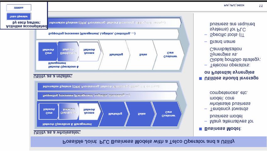
Table of Contents
1      INTRODUCTION ........................................................................................................ 1
2      EXECUTIVE SUMMARY........................................................................................... 2
3      BROADBAND ACCESS ALTERNATIVES ................................................................ 4
    3.1     DIGITAL SUBSCRIBER LINE (DSL) - BROADBAND OVER FASTER COPPER......................4
      3.1.1     Advantages of DSL.......................................................................................... 4
      3.1.2     Limitations of DSL........................................................................................... 4
      3.1.3     DSL Variations................................................................................................ 5
    3.2     FIBER TECHNOLOGIES ..............................................................................................8
    3.3     COAXIAL CABLE ......................................................................................................8
      3.3.1     Advantages and Disadvantages of Coaxial cable ............................................... 9
    3.4     WIRELESS ................................................................................................................9
      3.4.1     Unlicensed Wireless......................................................................................... 9
         Wi-Fi........................................................................................................................10
         WiMax .....................................................................................................................11
         Wi-Fi vs. WiMax.......................................................................................................13
      3.4.2     Fixed Wireless Technologies.......................................................................... 14
         Multi-channel multipoint distribution service (MMDS)................................................14
         Local multip oint distribution service (LMDS) .............................................................14
      3.4.3     Satellite......................................................................................................... 15
    3.5     COMPARATIVE ANALYSIS OF ACCESS ALTERNATIVES ..............................................16
4      WHAT IS BPL? ......................................................................................................... 17
    4.1       DEFINITIONS..........................................................................................................17
    4.2       AN OVERVIEW OF HOW BPL WORKS......................................................................20
5      INDUSTRY STRUCTURE – KEY ENABLING PARTNERS.................................... 23
6      IMPETUS FOR BPL AS AN ACCESS TECHNOLOGY ........................................... 25
    6.1     HOMELAND SECURITY AND NETWORK BENEFITS.....................................................25
    6.2     CONSUMER BENEFITS.............................................................................................25
      6.2.1     Is BPL Truly A Low Cost Alternative?............................................................. 26
      6.2.2     Geographical Coverage And Availability ........................................................ 27
      6.2.3     A Better-Connected Appliance........................................................................ 28
    6.3     COMMERCIAL OPPORTUNITIES................................................................................28
      6.3.1     Overview Of Different Applications That Can Be Offered With BPL ................. 28
      6.3.2     Financial Impact Of Delivering Utility Applications Via BPL........................... 29
      6.3.3     BPL Business Models..................................................................................... 31
         The Landlord Model..................................................................................................31
         The Developer Model................................................................................................32
         The Service Provider Model.......................................................................................32
    6.4     SUPPORT FROM FEDERAL REGULATORS ..................................................................34
7      FEASIBILITY ASSESSMENT................................................................................... 35
    7.1     TECHNICAL ...........................................................................................................35
      7.1.1     Vendor Systems And Architectures.................................................................. 36
         Architecture #1..........................................................................................................36
         Architecture #2..........................................................................................................37

                                                                   i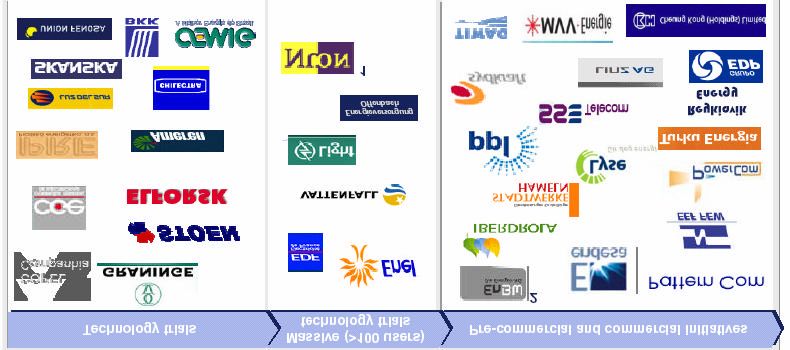
Architecture #3..........................................................................................................38
         Potential Architectures And Their Financial Attractiveness ..........................................39
    7.2     REGULATORY - ISSUES AND CHALLENGES ...............................................................43
      7.2.1     Interference and Radio Static ......................................................................... 44
      7.2.2     Universal Service and Pole Attachments ......................................................... 45
      7.2.3     Open Access.................................................................................................. 46
      7.2.4     Local/State Issues .......................................................................................... 47
      7.2.5     Cross-subsidies ............................................................................................. 48
8      MARKET DYNAMICS.............................................................................................. 49
    8.1     THE BROADBAND MARKET ....................................................................................49
    8.2     COMPETITIVE P OSITION OF BPL.............................................................................50
    8.3     CABLE AS A COMPETITOR .......................................................................................52
      8.3.1     DSL as a Competitor...................................................................................... 53
      8.3.2     Wireless as a competitor ................................................................................ 53
9      INDUSTRY INITIATIVES AND TRIALS................................................................. 55
    9.1     OVERVIEW OF NORTH AMERICAN BPL TRIALS ........................................................55
      9.1.1    Commercial BPL Systems............................................................................... 55
      9.1.2    Selected BPL Trials In North America ............................................................ 56
    9.2     OVERVIEW OF EUROPEAN BPL ACTIVITIES ..............................................................57
      9.2.1    BPL Deployments at varying stages across the world....................................... 57
      9.2.2    Utilities in Europe are very much involved in BPL........................................... 58
      9.2.3    Operating Structure....................................................................................... 59
10         INDUSTRY PERSPECTIVES................................................................................ 60
    10.1      NATIONAL TELECOMMUNICATIONS & INFORMATION ADMINISTRATION (NTIA)........60
    10.2      FEDERAL EMERGENCY MANAGEMENT AGENCY (FEMA).........................................60
    10.3      AMERICAN RADIO RELAY LEAGUE (ARRL) ............................................................60
    10.4      INSTITUTE OF ELECTRICAL AND ELECTRONICS ENGINEERS (IEEE)............................60
    10.5      AMERICAN P UBLIC P OWER ASSOCIATION (APPA)...................................................61
11         INFORMATION SOURCES.................................................................................. 61
    11.2      CONSULTANTS’ REPORTS .......................................................................................61
12         APPENDICES........................................................................................................ 61
    12.1 APPENDIX A: BUSINESS CASE RESULTS FOR MULTIPLE ARCHITECTURES ....................61
      12.1.1 Minneapolis/St.Paul Market........................................................................... 61
      12.1.2 Syracuse Market............................................................................................ 62
      12.1.3 Lynchburg..................................................................................................... 62
13         LIST OF FIGURES................................................................................................ 63
14         LIST OF TABLES.................................................................................................. 63

                                                                 ii
1 Introduction
The Ratepayer Advocate represents and protects the interests of all utility consumers - residential,
small business, commercial and industrial - each time companies in New Jersey seek changes in
how much they charge customers for natural gas, electric, water, wastewater or telephone service.
The Ratepayer Advocate also represents consumers in setting energy and telecommunications
policy that will affect the provision of services into the future.

The mission of the Ratepayer Advocate is to make sure that all classes of utility consumers
receive safe, adequate and proper utility service at affordable rates that are just and
nondiscriminatory. In addition, the Ratepayer Advocate works to insure that all consumers are
knowledgeable about the choices they have in the emerging age of utility competition.

Consistent with its mission, the Division of Ratepayer Advocate presents an overview and
assessment of technical feasibility of Broadband over Power Lines (BPL), prospects of BPL as a
significant competitor in the industry, and associated regulatory control issues.

                                                 1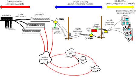
2 Executive Summary

Despite the spread of broadband technology in the last few years, there are significant areas of the
world that don't have access to high-speed Internet. When weighed against the relatively small
number of customers Internet providers would gain, the incremental expenditures of laying cable
and building the necessary infrastructure to provide DSL or cable in many areas, especially rural,
is too great. But if broadband could be served through power lines, there would be no need to
build a new infrastructure. Anywhere there is electricity there could be broadband.

Technology to deliver high-speed data over the existing electric power delivery network is closer
to reality in the marketplace. Broadband Over Powerline, is positioned to offer an alternative
means of providing high-speed internet access, Voice over Internet Protocol (VoIP), and other
broadband services, using medium – and low – voltage lines to reach customers’ homes and
businesses. By combining the technological principles of radio, wireless networking, and
modems, developers have created a way to send data over power lines and into homes at speeds
between 500 kilobits and 3 megabits per second (equivalent to DSL and cable). By modifying the
current power grids with specialized equipment, the BPL developers could partner with power
companies and Internet service providers to bring broadband to everyone with access to
electricity.

The technology evolution in the next few years is important from a perspective of future
competitive position of BPL as new networks are built and alternative technologies emerge. (See
Table 3.5 for comparison of access technologies). Fiber and advanced wireless broadband are the
new alternative broadband access systems that are most likely to emerge in the next few years.
These could also become a part of an integrated BPL system.

Federal policy support is also strengthening the potential for BPL deployment. The FCC and
others have hailed BPL as a potential “third wire” that may help increase the availability and
affordability of broadband services in a market dominated by digital subscriber line (DSL) and
cable modem service. As part of the federal effort to remove barriers to BPL implementation, the
FCC issued a change to Part 15 rules for measures to mitigate radio interference caused by
broadband over powerline. The FCC ruling on October 14, 2004 would essentially help to
overcome BPL’s potential to cause interference with radio and telecommunications signals.

However, a number of jurisdictional and classification issues remain open. For example, are the
broadband services offered via BPL considered an information service or a telecommunications
service? This has implications since telecommunications services are subject to regulations under
the Telecommunications Act of 1996, most notably common carrier requirements. As of October
2004, the FCC has two proceedings that address the issue of broadband regulatory classification:
one deals with cable modem services and another addressing all wireline broadband Internet
access services generally. If classified as an information services, BPL service would be free from
many if not all common carrier regulations except, contribution to the universal service fund
(USF).

Reliability and safety of the power delivery system and provision of quality service are the main
concerns for state commissions. In addition, affiliate transaction policies and cross subsidization
issues are major concerns. State Commissions are obligated to prevent the unfair use of an asset
developed with ratepayer funds for the benefit of shareholders. They are also obligated to ensure

                                                 2
that electric utilities do not have an unfair advantage over competitors. Thus several solutions
such as creation of unregulated BPL subsidiaries or implementation of accounting rules that
guard against cross subsidization may be considered.

The state regulators will also need to address rights of way, and access to poles issues. For
instance, some municipalities may seek to charge fees for BPL rights of way. Pole attachment
rules may also need to be addressed because of potential interference problems.

The technical feasibility, the FCC rulemaking mitigating interference, and the announcements of
the commercial-scale tests of BPL have stimulated considerable interest in BPL among electric
utilities, with several now evaluating deployment of BPL. The market trials and commercial
deployments will reveal business case attractiveness of BPL compared to established DSL and
cable services. However, there is also interest in BPL’s potential to serve as a communications
system that can support the network management of the power delivery system. The electric
utilities will determine if the combined benefits of a system allowing for consumer telecom
services, other consumer services, and core utility network communications help make the
business model attractive for BPL.

Utilities can consider applying three basic simplified business case models:

    •   The Landlord Model – leasing the conduit and assets to a third party, probably with a
        maintenance arrangement
    •   The Developer Model – a partnership or contract with an Internet service provider (ISP);
        the utility builds and owns the infrastructure, and the ISP handles all aspects of
        marketing, selling to and servicing the customer
    •   The Service Provider Model – utility manages the system, including serving as the
        Internet service provider

Each utility will assess BPL according to its own business objectives, risk tolerance, and
procedures. The factors to evaluate are cost, market size and price, differentiating features of
BPL, bundled services and average revenue per user, and the utility applications. While
broadband Internet access may be the primary application that is the impetus for deployment of
BPL networks, the range of potential applications using such a communications network is
enormous and needs to be considered as the business model is developed.

                                                 3
3 Broadband Access Alternatives
Broadband access and services are delivered using a variety of technologies, network
architectures and transmission methods. The most significant broadband technologies include:
• Digital Subscriber Line (DSL)
• Fiber Technologies
• Coaxial Cable
• Wireless
• BPL (Broadband Over Power Lines)
The following is a brief description of each of the above referenced access technology.
3.1 Digital Subscriber Line (DSL) - Broadband over faster copper
DSL is a very high-speed connection to Internet that uses the same wires as a regular telephone
line. A standard telephone installation in the United States consists of a pair of copper wires. This
pair of copper wires has sufficient bandwidth for carrying both data and voice. Voice signals use
only a fraction of the available capacity on the wires. DSL exploits this remaining capacity to
carry information on the wire without affecting the line’s ability to carry voice conversations.
Standard phone service limits the frequencies that the switches, telephones and other equipment
can carry. Human voices, speaking in normal conversational tones, can be carried in a frequency
range of 400 to 3,400 Hertz (cycles per second). In most cases, the wires themselves have the
potential to handle frequencies of up to several-million Hertz. Modern equipment that sends
digital (rather than analog) data can safely use much more of the telephone line’s capacity, and
DSL does just that.
3.1.1 Advantages of DSL
• Simultaneous Use - Phone line can be used for voice calls and the Internet connection
at the same time.
• A much higher speed when compared to regular modem (1.5 Mbps vs. 56 Kbps).
• Does not necessarily require new wiring, the existing phone line can be used.
• Providers generally include modem as part of the installation.
3.1.2 Limitations of DSL
• The quality of connection depends upon the proximity to the provider’s central
office, closer the better
• Receiving data is faster than sending data over the internet
• DSL is not available everywhere
43.1.3 DSL Variations
There are several variations of DSL technology. Often the term xDSL, where x is a variable, is
used to discuss DSL in general.
1. Asymmetric DSL (ADSL) - It is called “asymmetric” because the download speed is greater
than the upload speed. ADSL works this way because most Internet users look at, or download,
much more information than they send, or upload.
2. High bit-rate DSL (HDSL) - Providing transfer rates comparable to a T1 line (about 1.5 Mbps),
HDSL receives and sends data at the same speed, but it requires two lines that are separate from
your normal phone line.
3. ISDN DSL (ISDL) - Geared primarily toward existing users of Integrated Services Digital
Network (ISDN), ISDL is slower than most other forms of DSL, operating at fixed rate of 144
Kbps in both directions. The advantage for ISDL customers is that they can use their existing
equipment, but the actual speed gain is typically only 16 Kbps (ISDN runs at 128 Kbps).
4. Multi-Rate Symmetric DSL (MSDSL) - This is Symmetric DSL that is capable of more than one
transfer rate. The transfer rate is set by the service provider, typically based on the service (price)
level.
5. Rate Adaptive DSL (RADSL) - This is a popular variation of ADSL that allows the modem to
adjust the speed of the connection depending on the length and quality of the line.
6. Symmetric DSL (SDSL) - Like HDSL, this version receives and sends data at the same speed.
While SDSL also requires a separate line from your phone, it uses only a single line instead of the
two used by HDSL.
7. Very high bit-rate DSL (VDSL) - An extremely fast connection, VDSL is asymmetric, but only
works over a short distance using standard copper phone wiring.
8. Voice-over DSL (VoDSL) - A type of IP Telephony, VoDSL allows multiple phone lines to be
combined into a single phone line that also includes data-transmission capabilities.
Most homes and small business users are connected to an asymmetric DSL (ADSL) line. ADSL
divides up the available frequencies in a line on the assumptio n that most Internet users look at, or
download, much more information than they send, or upload. Under this assumption, if the
connection speed from the Internet to the user is three to four times faster than the connection
from the user back to the Internet, then the user will see the most benefit (most of the time).
Precisely how much benefit a user will see depends on how far the user is from the central office
of the company providing the ADSL service. ADSL is a distance-sensitive technology: As the
connection’s length increases, the signal quality decreases and the connection speed goes down.
The limit for ADSL service is 18,000 feet (5,460 meters), though for speed and quality of service
many ADSL providers place a lower limit on the distances for the service. At the extremes of the
distance limits, ADSL customers may see speeds far below the promised maximums, while
customers nearer the central office have faster connections and may see extremely high speeds in
the future. ADSL technology can provide maximum downstream (Internet to customer) speeds of
up to 8 megabits per second (Mbps) at a distance of about 6,000 feet (1,820 meters), and
upstream speeds of up to 640 kilobits per second (Kbps). In practice, the best speeds widely
offered today are 1.5 Mbps downstream, with upstream speeds varying between 64 and 640
Kbps.
5Distance is a limitation for DSL but not for voice telephone calls. This is because the voice
signals are boosted (amplified) with small amplifiers called loading coils. These loading coils are
incompatible with ADSL signals, so a voice coil in the loop between a telephone and the
telephone company’s central office will disqualify a user from receiving ADSL. Other factors that
might disqualify a user from receiving ADSL include:
Bridge taps - These are extensions, between the user and the central office, that extend service to
other customers. While the users would not notice these bridge taps in normal phone service, they
may take the total length of the circuit beyond the distance limits of the service provider.
Fiber-optic cables - ADSL signals cannot pass through the conversion from analog to digital and
back to analog that occurs if a portion of a telephone circuit comes through fiber-optic cables.
Distance - Even if you know where your central office is (don’t be surprised if you don’t—the
telephone companies don’t advertise their locations), looking at a map is no indication of the
distance a signal must travel between your house and the office.
ADSL uses two pieces of equipment, one on the customer end and one at the provider end:
• At the customer’s location, there is a DSL transceiver, which may also provide other
services. Most residential customers call their DSL transceiver a DSL modem. The
engineers at the telephone company or ISP call it an ATU-R, which stands for ADSL
Transceiver Unit - Remote. Regardless of what it is called, the transceiver is the point
where data from the user’s computer or network is connected to the DSL line. The
transceiver can connect to a customer’s equipment in several ways, though most
residential installations use Universal Serial Bus (USB) or 10BaseT Ethernet
connections. Most of the ADSL transceivers sold by ISPs and telephone companies are
simply transceivers, but the devices used by businesses may combine network routers,
network switches or other networking equipment in the same box.
• The DSL service provider has a DSL Access Multiplexer (DSLAM) to receive customer
connections. The DSLAM at the access provider is the equipment that makes DSL
happen. A DSLAM takes connections from many customers and aggregates them onto a
single, high-capacity connection to the Internet. DSLAMs are generally flexible and able
to support multiple types of DSL, as well as provide additional functions such as routing
and dynamic IP address assignment for customers.
VDSL (defined above) is seen by many as the next step in providing a complete home -
communications/ entertainment package. There are already some companies, such as U.S. West
(part of Qwest now), that offer VDSL service in selected areas.
VDSL operates over the copper wires in much the same way that ADSL does, but there are a
couple of distinctions. VDSL can achieve incredible speeds, as high as 52 Mbps downstream and
16 Mbps upstream. That is much faster than ADSL, which provides up to 8 Mbps downstream
and 800 Kbps (kilobits per second) upstream. However, VDSL’s is distance sensitive. It can only
operate over the copper line for a short distance, about 4,000 feet (1,200 m).
Compared to a maximum speed of 8 to 10 Mbps for ADSL or cable modem, it is clear that the
move from current broadband technology to VDSL could be as significant as the migration from
a 56K modem to broadband. However, the key to VDSL is that the telephone companies are
replacing many of their main feeds with fiber-optic cable. In fact, many phone companies are
planning Fiber to the Curb (FTTC), which means that they will replace all existing copper lines
right up to the point where a phone line branches off to a house. At the least, most companies
expect to implement Fiber to the Neighborhood (FTTN). Instead of installing fiber-optic cable
along each street, FTTN has fiber going to the main junction box for a particular neighborhood.
6By placing a VDSL transceiver in a home and a VDSL gateway in the junction box, the distance
limitation is overcome. The gateway takes care of the analog-digital-analog conversion problem
that disables ADSL over fiber-optic lines. It converts the data received from the transceiver into
pulses of light that can be transmitted over the fiber-optic system to the central office, where the
data is routed to the appropriate network to reach its final destination. When data is sent back to
the computer, the VDSL gateway converts the signal from the fiber-optic cable and sends it to the
transceiver.
There are two competing consortiums pushing to standardize VDSL. Their proposed standards
use carrier technologies that are incompatible with one another. The VDSL Alliance, a
partnership between Alcatel, Texas Instruments and others, supports VDSL using a carrier system
called Discrete MultiTone (DMT). According to equipment manufacturers, most of the ADSL
equipment installed today uses DMT.
The other VDSL group is called the VDSL Coalition. Led by Lucent and Broadcom, the
Coalition proposes a carrier system that uses a pair of technologies called Quadrature Amplitude
Modulation (QAM) and Carrierless Amplitude Phase (CAP).
While, VDSL provides a significant performance boost over any other version, for it to become
widely available, it must first be standardized. The following Table 2 .1.3 lists the DSL variations
and how they compare to each other.
Table 3.1.3: DSL Technologies Comparison
DSL Type Max. Send Speed Max Receive Speed Max Distance Lines Required
ADSL 800 Kbps 8 Mbps 1
18,000 ft
HDSL 1.54 Mbps 1.54 Mbps 12,000 ft. 2
IDSL 144 Kbps 144 Kbps 35,000 ft 1
MSDSL 2 Mbps 2 Mbps 29,000 ft 1
RADSL 1 Mbps 7 Mbps 18,000 ft 1
SDSL 2.3 Mbps 2.3 Mbps 22,000 ft 1
VDSL 16 Mbps 52 Mbps 4,000 ft 1
73.2 Fiber Technologies
In recent years, carriers have begun constructing entirely fiber optic cable transmission facilities
that run from a distribution frame (or its equiva lent) in an incumbent local exchange carrier’s
(ILEC’s) central office to the loop demarcation point at an end-user customer premise. These
loops are referred to as fiber-to-the-home (FTTH) loops. FTTH technology offers substantially
more capacity than any copper-based technology. For example, Wav7 Optics provides a FTTH
system today using commercially available equipment that delivers transmission speeds up to 500
Mbps shared over a maximum of 16 subscribers. This system can also provide up to 500 Mbps
symmetrically to one subscriber if desired. The speed an actual user will experience depends
upon the time of day and the number of users online. A typical FTTH system can deliver up to
870 MHz of cable television video services (for high definition television) or IP video services
along with multiple telephone lines and current and next-generation data services at speeds in
excess of 100 Mbps.
There are three basic types of architectures being used to provide FTTH. The most common
architecture used is Passive Optical Network (PON) technology. This technology allows multiple
homes to share a passive fiber network. In this type of network, the plant between the customer
premises and the head-end at the central office consists entirely of passive components – no
electronics are needed in the field. The other architectures being used are Home Run Fiber or
Point-to-Point Fiber, in which subscribers have a dedicated fiber strand, and active or powered
nodes are used to manage signal distribution, and hybrid PONs, which are a combination of home
run and PON architecture.
Although FTTH technology is still in its infancy, the deployment of FTTH is growing
significantly. Also, the equipment costs for FTTH have decreased significantly. As of May 2004,
carriers have deployed FTTH technology to 128 communities in 32 states. Companies plan to
deploy FTTH further in the future. Competitive carriers are also building FTTH facilities.
In addition to FTTH technologies, some carriers are constructing fiber-to-the-curb (FTTC)
facilities that do not run all the way to the home, but run to a pedestal located within 500 feet of
the subscriber premises. Copper lines are then used for the connection between the pedestal and
the network interface device at the customer’s premises. Because of the limited use of copper,
FTTC technologies permit carriers to provide high-speed data in addition to high definition video
services.
3.3 Coaxial Cable
For millions of people, television brings news, entertainment and educational programs into their
homes. Many people get their TV signal from cable television (CATV) because cable TV
provides better reception and more channels.
Many people who have cable TV can now get a high-speed connection to the Internet from their
cable provider. Cable modems allow subscribers to access high-speed data services over cable
systems that are generally designed with hybrid fiber-coaxial (HFC) architecture. Cable modem
service is primarily residential, but may also include some small business service.
Cable modems compete with technologies like Asymmetrical Digital Subscriber Lines (ADSL).
Following is a look at how a cable modem works and how 100 cable television channels and web
sites can flow over a single coaxial cable.
In a cable TV system, signals from the various channels are each given a 6-MHz slice of the
cable’s available bandwidth and then sent down the cable to your house. The coaxial cable used
8to carry cable television can carry hundreds of megahertz of signals and therefore, a large number
of channels. In some systems, coaxial cable is the only medium used for distributing signals. In
other systems, fiber-optic cable goes from the cable company to different neighborhoods or areas.
Then the fiber is terminated and the signals move onto coaxial cable for distribution to individual
houses.
When a cable company offers Internet access over the cable, Internet information can use the
same cables because the cable modem system puts downstream data—data sent from the Internet
to an individual computer—into a 6-MHz channel. On the cable, the data looks just like a TV
channel. So Internet downstream data takes up the same amount of cable space as any single
channel of programming. Upstream data—information sent from an individual back to the
Internet—requires even less of the cable’s bandwidth, just 2 MHz, since the assumption is that
most people download far more information than they upload.
Putting both upstream and downstream data on the cable television system requires two types of
equipment: a Cable Modem on the customer end and a Cable Modem Termination System
(CMTS) at the cable provider’s end. Between these two types of equipment, all the computer
networking, security and management of Internet access over cable television is put into place.
3.3.1 Advantages and Disadvantages of Coaxial cable
If you are one of the first users to connect to the Internet through a particular cable channel, then
you may have nearly the entire bandwidth of the channel available for your use. The
disadvantage of coaxial cable however, is as new users, especially heavy-access users, are
connected to the channel, you will have to share that bandwidth, and may see your performance
degrade as a result. It is possible that, in times of heavy usage with many connected users,
performance will be far below the theoretical maximums. The cable company can resolve this
particular performance issue by adding a new channel and splitting the base of users.
Another benefit of the cable modem for Internet access is that, unlike ADSL, its performance
does not depend on distance from the central cable office. A digital CATV system is designed to
provide digital signals at a particular quality to customer households. On the upstream side, the
burst modulator in cable modems is programmed with the distance from the head-end, and
provides the proper signal strength for accurate transmission.
Cable industry has extended the broadband services offering to at least 90 percent of homes
passed by cable systems. The cable industry expects that industry-wide facilities upgrades
enabling the provision of broadband Internet access to residential customers will be completed in
the near future.
3.4 Wireless
3.4.1 Unlicensed Wireless
Since the Commission first allocated spectrum in the 902-928 MHz band for use on an unlicensed
basis under Part 15 of the rules, there has been an increasingly rapid expansion of products and
markets in bands designated for unlicensed use. This Industrial, Scientific, and Medical (ISM)
band was the first to experience the large-scale introduction of devices such as cordless phones,
security alarms, wireless bar code readers, and data collection systems. A number of original
equipment manufacturers continue to provide equipment for point-to-point and point-to-
multipoint systems for such applications as Supervisory Control and Data Acquisition. In
addition, there are several providers of wireless local area network equipment in this band.
9Wi-Fi
Wi-Fi, short for Wireless Fidelity, is a term that is used generically to refer to any product or
service using the 802.11 series standards developed by the Institute of Electrical and Electronics
Engineers (IEEE) for wireless local area network connections. Wi-Fi networks operate on an
unlicensed basis in the 2.4 and 5 GHz radio bands and provide multiple data rates up to a
maximum of 54 Mbps. The bandwidth is shared among multiple users. Wi-Fi enabled wireless
devices, such as laptop computers or personal digital assistants (PDAs), can send and receive data
from any location within signal reach of a Wi-Fi equipped base station or access point (AP).
Typically, mobile devices must be within approximately 300 feet of a base station.
The Wi-Fi technology features a creation of a “wireless cloud” that covers a hot-spot area. The
specific dimensions of the coverage area vary based on environmental and power specifications
of the equipment in use. Typically, coverage radius is in the range of 300-500 feet. Environmental
conditions, like weather and line of site, can affect the ability to reach target customers.
With the expansion of Wi-Fi access to the Internet there has been a rapid growth of hot-spots.
Networks of hot-spots consisting of many access points have been constructed to cover larger
areas such as airports.
The IEEE 802.11 wireless LAN standards describe four radio link interfaces that operate in the
2.4 GHz or 5 GHz unlicensed radio bands. These are summarized in Table 3.4.1.
10Table 3.4.1: IEEE 802.11 WLAN Radio Link Interfaces and Highlights
Max. Bit Fallback Number of Frequency
Standard Other Highlights
Rate Rate Channels Band
802.11 2 Mbps 1 Mbps 3 2.4 GHz
48 Mbps •Signal delivery is very short range,
36 Mbps limiting deployment potential
24 Mbps •Not backwards compatible with the
802.11a 54 Mbps 18 Mbps 12 5 GHz more widely used 802.11b
12 Mbps •Very poor ability to penetrate walls or
9 Mbps other obstructions
6 Mbps
•Most widely used WLAN platform
•Widespread deployment activity has
5.5 Mbps
resulted in significantly lower prices for
802.11b 11 Mbps 2 Mbps 3 2.4 GHz
equipment
1 Mbps
•Signal delivery is significantly stronger
than 802.11a
Same as
802.11g 54 Mbps 3 2.4 GHz •Backwards compatible with 802.11b
802.11a
•Products have begun to ship
Of all the different Wireless LAN interfaces, 802.11b has the most popular appeal due to the low
number of technical problems and lower hardware costs. It is the only standard with widespread
popularity and focused on residential users.
WiMax
Wireless Local Area Networks (LANs) based on the IEEE 802.11 or Wi-Fi standards have been
quite successful, and therefore the focus in wireless is moving towards the wide area. While Wi-
Fi dominates in the local area, the wide area market is still very much open.
The cellular carriers got into this market first with their 2.5G/3G data services, but they were
positioned to offer essentially add-on to voice service. The real competition to cellular data
services may come from emerging data-oriented technology, WiMax.
WiMax, short for Worldwide Interoperability for Microwave Access, refers to any broadband
wireless access network based on the IEEE 802.16 standards. Internationally, a European
Telecommunications Standards Institute (ETSI) initiative called HIPERMAN addresses the same
area as WiMax/802.16 and shares some of the same technology.
WiMax includes fixed systems employing a point-to-multipoint architecture operating between 2
GHz and 66 GHz. WiMax based broadband wireless access (BWA) or, also known as wireless
DSL, will offer data rates between 512 Kbps and 1 Mbps. The key will be to deliver low-cost,
11indoor, user installable premises devices that will not have to be aligned with the base station i.e.,
the antenna in the premises equipment would be integrated with the radio modem.
WiMax is designed to deliver a metro area broadband wireless access (BWA) service. The idea
behind BWA is to provide a fixed location wireless Internet access service to compete with cable
modems and DSL. WiMax systems could support users at ranges up to 30 miles and is intended
as the basis of a carrier service.
The WiMax standards include a much wider range of potential implementation to address the
requirements of carriers around the world. The original version of the 802.16 standard, when
released addressed systems operating in the 10 GHz to 66 GHz frequency band. Such high
frequency systems require line-of-sight (LOS) to the base station, which increases cost and limits
the customer base. Also, in LOS systems, customer antennas must be realigned when a new cell
is added to the network. Since the initial release, 802.16a standard released in 2003 has changed
the playing field. The standard 802.16a describes systems operating between 2 GHz and 11 GHz.
These lower frequency bands support non-line-of-sight (NLOS), thereby eliminating the need to
align the customer unit with the base station. Table 3.4.2 presents a summary of WiMax (802.16)
radio links.
Table 3.4.2 Summary of WiMax (802.16) Radio Links (Source needed)
Typical
Channel
Standard Spectrum Configuration Bit Rate Mobility Cell
Bandwidth
Radius
32 to 134
10-66 20, 25, 28
802.16 Line of Sight Mbps (28 MHz Fixed 1.3 miles
GHz MHz
Channel)Wi-Fi vs. WiMax
Wi-Fi and WiMax represent wireless applications from two completely different perspectives.
Wi-Fi is a local network technology designed to add mobility to private wired LANs. WiMax, on
the other hand, is designed to deliver a metro area broadband wireless access (BWA) service. The
idea behind BWA is to provide a fixed location wireless Internet access service to compete with
cable modems and DSL. While Wi-Fi supports transmission ranges up to a few hundred feet,
WiMax systems could support users at ranges up to 30 miles. While Wi-Fi is targeted at the end-
user, WiMax is intended as the basis of a carrier service. Besides the difference in transmission
range, there are a number of improvements in the radio link technology that separate WiMax
from Wi-Fi. Table 3.4.3 presents a comparison of Wi-Fi and WiMax Technologies:
Table 3.4.3: A comparison of WiMax and Wi-Fi
Wi-Fi WiMax
Wi-Fi (802.11a/g)
(802.11b) (802.16a)
Broadband Wireless
Primary Applications Wireless LAN Wireless LAN
Access
2.4 GHz ISM (g) Licensed/Unlicensed
Frequency Band 2.4 GHz ISM
5 GHz U-NII (a) 2 GHz to 11 GHz
Adjustable 1.25 MHz
Channel Bandwidth 25 MHz 20 MHz
to 20 MHz
Half/Full Duplex Half Half Full
Direct Sequence OFDM* OFDM*
Radio Technology
Spread Spectrum (64-channels) (256-channels)
Mobility In Development In Development Mobile WiMax
* 256 – Sub-Carrier Orthogonal Frequency Division Multiplexing
133.4.2 Fixed Wireless Technologies
Point-to-point microwave connections have a long history in the backhaul networks of
phone companies, cable TV companies, utilities and government agencies. In recent
years, technology has advanced to enable higher frequencies and smaller antennas. This
has resulted in lower cost systems that could be sold by carriers for the last mile of
communications.
Multi-channel multipoint distribution service (MMDS)
This band, located at 2.5GHz, was initially used to distribute cable television service.
Now MMDS is being developed for residential Internet service.
MMDS wireless technology can be deployed to offer “two-way” service at throughputs ranging
from 64 kbps to 10Mbps. However, MMDS systems require line of sight between transmitter and
receiver. The lower MMDS frequencies (2 GHz) do not attenuate very quickly and services can
be provided at up to 30 miles from the hub, equivalent to coverage of approximately 2,800 square
miles. This is one of the largest coverage areas of any point-to-multipoint communications system
available today.
Local multipoint distribution service (LMDS)
This band (27.5GHz to 28.35 GHz, 29.1GHz to 29.25 GHz and 31GHz to 31.3 GHz) is
being used for point-to-multipoint applications similar to the 39GHz band - Internet
access and telephony. LMDS, though, only has a 3-mile coverage radius and uses TDMA
(Time-Division Multiple Access) so that multiple customers can share the same radio
channel.
The technology uses a cellular like network architecture of microwave radios placed at the
client’s location and at the company’s base station to deliver fixed services, mainly telephony,
video and Internet access. The use of time-division multiple access (TDMA) and frequency-
division multiple access (FDMA) technologies allows multiple customers within a 3-5 mile
coverage radius to share the same radio channel. Customers can receive data rates between
64kbps to 155Mbps.
An LMDS system consists of four parts:
• The network operations center (NOC) houses the network management system (NMS)
equipment that manages large regions of the customer network.
• A fiber-based infrastructure connects separate NOCs.
• The base station, usually located on a cellular tower, is where the conversion from fibered
infrastructure to wireless infrastructure occurs.
• The customer premises equipment (CPE) typically includes microwave equipment mounted
on the outside of a consumer’s home or business as well as equipment located within the
building, providing modulation, demodulation, control, and interface functionality.
• Advantages of LMDS: Low entry and deployment costs - Due to the fact that a large part
of a wireless network’s cost is not incurred until the CPE is installed, the operator is able
to stage capital expenditures gradually with new customer acquisition.
• Speed of deployment - A fiberless network requires no trenches, backhoes or
construction, only a radio at the customer’s location and another one on a tower in a
central location. This enables a quicker deployment schedule than most broadband
services.
14• Demand-based buildout - LMDS uses a scalable architecture combined with industry
standards to ensure service can be expanded as customer demand increases.
• Variable component cost - Most wireline systems require a large capital investment for
the infrastructure component. LMDS systems shift the cost to the CPE, which means the
operator only spends money when a revenue-paying customer signs on.
Limitations of LMDS:
• The system requires line-of-site (LOS) between the CPE and base station hub. This could
require the use of repeaters to forward signals over obstacles.
• LMDS signals are affected by moisture, which could result in “rain fade,” or the
disruption of signals as a result of heavy rain. Increasing the power used to transmit the
signals can usually alleviate problems associated with rain fade.
3.4.3 Satellite
Satellite Internet access is ideal for rural Internet users who want broadband access. Satellite
Internet does not use telephone lines or cable systems, but instead uses a satellite dish for two-
way (upload and download) data communications. Upload speed is about one-tenth of the 500
kbps download speed. Cable and DSL have higher download speeds, but satellite systems are
about 10 times faster than a normal modem.
Two-way satellite Internet consists of approximately a two-foot by three-foot dish, two modems
(uplink and downlink), and coaxial cables between dish and modem. The key installation-
planning requirement is a clear view to the south, since the orbiting satellites are over the equator
area. And, like satellite TV, trees and heavy rains can affect reception of the Internet signals.
Two-way satellite Internet uses Internet Protocol (IP) multicasting technology, which means that
a maximum of 5,000 channels of communication can simultaneously be served by a single
satellite. IP multicasting sends data from one point to many points (at the same time) in a
compressed format. Compression reduces the size of the data and the bandwidth. Usual dial-up
land-based terrestrial systems have bandwidth limitations that prevent multicasting of this
magnitude.
The satellite data downlink is just like the usual terrestrial link, except the satellite transmits the
data to your computer via the same dish that would allow you to receive a Pay-Per-View
television program.
Figure 3.4.3: Graphic Courtesy of StarBand. StarBand's System
153.5 Comparative Analysis of Access Alternatives
The use of fast Internet connections has grown rapidly over the last few years. As more people
buy home computers and create home networks, the demand for broadband connections steadily
increases. Currently, Coaxial Cable (Cable Modems) and Asymmetric Digital Subscriber Line
(ADSL) dominate the industry. While both of these technologies provide Internet connections
that are many times faster than a 56K modem, they still are not fast enough to support the
integration of home services such as digital television and Video-On-Demand.
Table 3.5: Comparison of Access Technologies
Typical Prices per
Access Technology Speed Month Reach Remarks
$28 to $39
Ubiquitous electric Speeds same for upload and download;
BPL Commercial - up to 3 Mbps depending on speed
distribution network Number of Users affects the speed
Residences - 5 Mbps or higher and features
Available where cable has The speed of the signal varies by the number
been installed so some rural of users on the neighborhood network loop, it
Cable 1 Mbps to 3 Mbps $39 to $60 and suburban locations may degrades with high numbers of users. Cable
not have access company may add another channel or split
the users into small groups
In general, a residence must
be within about 18,000 ft. of
DSL 1.5 Mbps $27 to $49 the DSL central equipment Not capable of transmitting TV signals
Cost reductions enabled by passive optical
$28 to $65
networks and advances in component
depending on Deployment has been
Fiber 30 Mbps to 1 Gbps technology are expected to bring costs down.
locale, service limited by high costs
Some telecom companies are already
features, and speed
installing Fiber.
Requires a clear view to the Trees and even heavy rain may affect
Satellite 500 Kbps reception on Internet data
$50 to $100 south
164 What is BPL?
4.1 Definitions
Broadband over Power Line (BPL) is a technology that allows voice and Internet data to be
transmitted over utility power lines. BPL is also sometimes called Power-line Communications or
PLC. Many people use the terms PLC and BPL interchangeably. The FCC chose to use the term
“broadband over power line” for consumer applications.
In order to make use of BPL, subscribers use neither a phone, cable nor a satellite connection.
Instead, a subscriber installs a modem that plugs into an ordinary wall outlet and pays a
subscription fee similar to those paid for other types of Internet service.
On April 23, 2003, the FCC adopted a Notice of Inquiry (Inquiry)1, expressing enthusiasm about
the potential of the BPL technology to enable electric power lines to function as a third wire into
the home, and create competition with the copper telephone line and cable television coaxial
cable line. The Commission subsequently issued a Notice of Proposed Rulemaking (NPRM)2 in
February 2004 based on the comments received in response to the Inquiry. Both the Inquiry and
NPRM discusses two types of BPL: 1) Access BPL, and 2) In-house BPL.
Access BPL3 is a technology that provides broadband access over medium voltage power lines.
Medium voltage power lines are the electric lines that you see at the top of electric utility poles
beside the roadways in areas that do not have underground electric service. Typically there are
three electric lines (called phases A, B and C), each carrying several thousand volts. One phase is
usually enough to power the houses on a residential street, two or even three phases can be joined
together to power the big electric motors in an industrial or commercial area. (You also may see a
fourth wire that is the ground wire.)
1
/ In April 2003, the Commission issued a Notice of Inquiry (Inquiry) on BPL technologies and
systems. The Inquiry was issued to solicit comments to assist the Commission in reviewing its Part 15 rules
to facilitate the deployment of Access BPL while ensuring that licensed services continue to be protected.
In the Inquiry, the Commission encouraged continued deployment of Access BPL systems that comply
with the existing rules. See Inquiry Regarding Carrier Current Systems, Including Broadband over Power
Line Systems, Notice of Inquiry, ET Docket No. 03-104, 18 FCC Rcd 8498 (2003).
2
/ In the Matter of Carrier Current Systems, including Broadband over Power Line Systems and
Amendment of Part 15 regarding new requirements and measurement guidelines for Access Broadband
over Power Line Systems, Notice of Proposed Rulemaking (NPRM), ET Docket Nos. 03-104 and 04-37,
19 FCC Rcd 3335 (2004).
3
/ The FCC’s Report and Order on BPL defines Access BPL as:
A carrier current system installed and operated on an electric utility service as an unintentional
radiator that sends radio frequency energy on frequencies between 1.705 MHz and 80 MHz over
medium voltage lines or low voltage lines to provide broadband communications and is located on
the supply side of the utility service’s points of interconnections with customer premises.
In The Matter of Amendment of Part 15 regarding new requirements and measurement guidelines for
Access Broadband over Power Line Systems; Carrier Current Systems, including Broadband over Power
Line Systems, Report and Order, ET Docket Nos. 03-104 and 04-37, para. 29 (rel. Oct. 28, 2004). (“BPL
Report and Order”).
17In-house BPL4 is a home networking technology that uses the transmission standards developed
by the HomePlug Alliance5 . In-house BPL products can comply relatively easily with the radiated
emissions limits in Part 156 of the FCC’s Rules, because the products connect directly with the
low voltage electric lines inside your home or office.
In-home networking, while exciting and innovative, is not a major policy concern for the FCC.
What the FCC is really wrestling with is how to get broadband Internet access over “the last
mile” to the home.
The Last Mile is the portion of the network that connects end users, such as homes and business,
to high-speed services and the Internet. For residential broadband service customers who get
cable modem service, for example, the drop wire connecting the interface on a house to cable
company’s network and the wire from the interface connecting to the wall plates in the home
would all be part of the last mile.
BPL modems use silicon chips designed to send signals over electric power lines, much like
cable and DSL modems use silicon chips designed to send signals over cable and telephone lines.
Advances in processing power have enabled new BPL modem chips to overcome difficulties in
sending communications signals over the electric power lines.
Inductive couplers are used to connect BPL modems to the medium voltage power lines. An
inductive coupler transfers the communications signal onto the power line by wrapping around
the line, without directly connecting to the line. A major challenge is how to deliver the signal
from the medium voltage line to the low voltage line that enters your house, because the
transformer that lowers the electric power from several thousands volts down to 220/110 is a
potential barrier to the broadband signal.
Router is a device that acts as an interface between two networks and provides network
management functions.
Repeater is a physical-layer hardware device used on a network to extend the length, topology,
or interconnectivity of the physical medium beyond that imposed by a single segment.
Concentrator/Injector is a device that aggregates the end-user CPE data onto the MV (medium
voltage) grid. Injectors are tied to the Internet backbone via fiber of T1 lines and interface to the
MV power lines feeding the BPL service area.
4
/ The FCC’s Report and Order on BPL defines In-House BPL as:
A carrier current system , operating as an unintentional radiator, that sends radio frequency energy
to provide broadband communications on frequencies between 1.705 MHz and 80 Mhz over low-
voltage electric power lines that are owned, operated or controlled by an electric service provider.
The electric power lines may be aerial (overhead), underground, or inside walls, floors or ceilings
of user premises.
See BPL Report and Order, para. 30.
5
/ Home Plug Alliance is made up of industry-leading companies working to define how the items in
your home connect to each other and to the Internet. The Alliance’s mission is to enable and promote rapid
availability, adoption and implementation of cost effective, interoperable and standards-based in-home
powerline networks and products. See www.homeplug.org.
6
/ Part 15 of the FCC’s Rules governs interference issues between unlicensed devices, including
BPL modems, and other electronic devices. All electronic devices sold in the U.S. have to meet FCC radio
frequency (RF) emissions limits.
18You can also read