2017 Sierra Nevada Corporation - Space Technologies Product Catalog
←
→
Page content transcription
If your browser does not render page correctly, please read the page content below

Space Systems                                  Space Technologies Product Catalog

                              Sierra Nevada Corporation’s Space Systems
                                  Space Technologies Product Catalog

                                                                Contact: SNC’s Space Systems, Space Technologies
                                                       1722 Boxelder Street • Louisville, CO 80027 USA • 303-530-1925
                                                             www.sncspace.com/catalog • Email: ssg@sncorp.com
©2017 Sierra Nevada Corporation                                                                                         i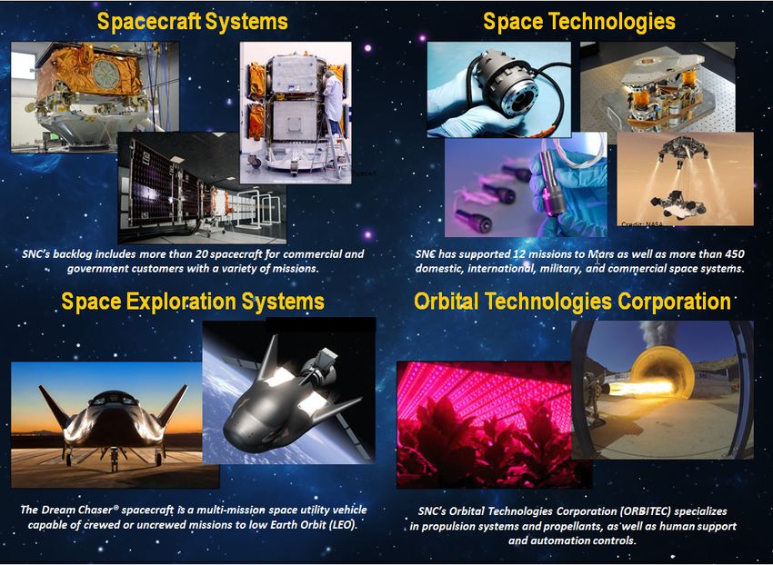
Space Systems                                                                                                     Space Technologies Product Catalog

           Table of Contents
           Space Technologies Product Catalog ........................................................................................................................................... i
                 Table of Contents .................................................................................................................................................................. ii
                 Introduction ........................................................................................................................................................................... 1
           Deployable Systems .................................................................................................................................................................... 7
                 Jackscrew Deployed Boom ................................................................................................................................................... 8
                 K-truss Boom ...................................................................................................................................................................... 10
           Docking and Berthing Systems .................................................................................................................................................. 11
                 Passive Common Berthing Mechanism (PCBM)................................................................................................................. 12
           Electrical Power Systems ........................................................................................................................................................... 14
                 Cell Shorting Device (CSD) Battery Switch ......................................................................................................................... 15
                 Cubesat Solar Array System—13 W Surface Mount Technology ....................................................................................... 17
                 Microsat Articulated Solar Array System— 400 W Articulated Array .................................................................................. 19
                 Microsat Rigid Panel Solar Array System—250 W Deployable Array ................................................................................. 21
                 Smallsat Solar Array System—780 W Articulated Array ..................................................................................................... 23
           Flight Control Systems (FCS) and Thrust Vector Control (TVC) Systems ................................................................................. 25
                 Flight Control (FCS) and Thrust Vector Control Systems (TVC) ......................................................................................... 26
           High Output Paraffin Actuators and Mechanisms ...................................................................................................................... 28
                 EH-3525 High Output Paraffin (HOP) Actuator ................................................................................................................... 29
                 IH-5055/-10055 High Output Paraffin (HOP) Actuators ...................................................................................................... 31
                 PP-35055 Resettable High-Force Pin Puller ....................................................................................................................... 33
                 PP-5501 Two-Position Latching Actuator ........................................................................................................................... 35
                 RO-9015 Two-Position Rotary Latching Actuator ............................................................................................................... 37
                 SP-5025 High Output Paraffin (HOP) Actuator ................................................................................................................... 39
           Instrument Door and Cover Systems ......................................................................................................................................... 41
                 Instrument Door and Cover Systems .................................................................................................................................. 42
           Launch Adapters and Separation Systems ................................................................................................................................ 44
                 Fast-Acting Shockless Separation Nut (FASSN) 30K ......................................................................................................... 45
                 Hold Down Release Mechanism (HDRM) ........................................................................................................................... 47
                 Low Shock Release Mechanism (LSRM) 5K ...................................................................................................................... 49
                 Microsat Deployment Module.............................................................................................................................................. 51
                 QwkSep 15 Low-Profile Separation System (LPSS) ........................................................................................................... 53
                 QwkSep 24 Low-Profile Separation System (LPSS) ........................................................................................................... 55

                                                                                                                                Contact: SNC’s Space Systems, Space Technologies
                                                                                                                       1722 Boxelder Street • Louisville, CO 80027 USA • 303-530-1925
                                                                                                                             www.sncspace.com/catalog • Email: ssg@sncorp.com
©2017 Sierra Nevada Corporation                                                                                                                                                                               ii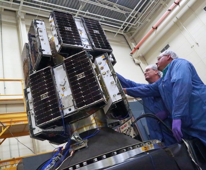
Space Systems                                                                                                      Space Technologies Product Catalog

           Pointing Systems and Motion Control ........................................................................................................................................ 57
                 C14 Bi-Axis Gimbal ............................................................................................................................................................. 58
                 C14 Incremental Rotary Actuator ........................................................................................................................................ 60
                 C14–750 W Solar Array Assembly...................................................................................................................................... 62
                 C20 Incremental Rotary Actuator ........................................................................................................................................ 64
                 C50 Incremental Rotary Actuator ........................................................................................................................................ 66
                 Electronic Control Unit (ECU) ............................................................................................................................................. 68
                 EH25 Bi-Axis Gimbal, 3-Phase ........................................................................................................................................... 70
                 EH25 Compact Incremental Rotary Actuator, 3-Phase ...................................................................................................... 72
                 EH25 Incremental Rotary Actuator, 3-Phase ...................................................................................................................... 74
                 eMotor ................................................................................................................................................................................. 76
                 H25 Bi-Axis Gimbal, 4-Phase.............................................................................................................................................. 78
                 LDC20 Low-Disturbance Gimbal......................................................................................................................................... 80
                 Lightweight 2-Axis Mini Gimbal ........................................................................................................................................... 82
                 Rotary Drive Electronics (RDE)........................................................................................................................................... 84
                 Size 23 Incremental Rotary Actuator .................................................................................................................................. 86
                 T25 Incremental Rotary Actuator (RA) ................................................................................................................................ 88
                 Universal Microstepping Control Driver (UMCD)................................................................................................................. 90
           Production and Test Capabilities................................................................................................................................................ 92
                 Cable and Harnessing Capability ........................................................................................................................................ 93
           Thermal Control Systems ........................................................................................................................................................... 95
                 Miniature Satellite Energy-Regulating Radiator (MiSER) .................................................................................................... 96
                 Passive Thermal Control Heat Switch................................................................................................................................. 98
                 Passive Thermal Louvers.................................................................................................................................................. 100
                 Thin Plate Heat Switch ...................................................................................................................................................... 102
           Acronym List ............................................................................................................................................................................ 104

                                                                                                                                 Contact: SNC’s Space Systems, Space Technologies
                                                                                                                        1722 Boxelder Street • Louisville, CO 80027 USA • 303-530-1925
                                                                                                                              www.sncspace.com/catalog • Email: ssg@sncorp.com
©2017 Sierra Nevada Corporation                                                                                                                                                                                iii
Space Systems                                                                   Space Technologies Product Catalog

           Introduction
           SNC’s Space Systems Overview
           Sierra Nevada Corporation (SNC), headquartered in Sparks, Nevada, provides customer-focused technology
           solutions in the areas of aerospace, aviation, electronics, and systems integration. SNC has been honored as one
           of “The World’s Top 10 Most Innovative Companies in Space,” and is one of America’s fastest growing
           companies. SNC’s diverse technologies are used in applications including telemedicine, navigation and guidance
           systems, threat detection and security, commercial aviation, scientific research, and infrastructure protection. The
           SNC enterprise provides customers with a wide array of capabilities via its six business areas: Space Systems
           (SS); Communication, Navigation, Surveillance/Air Traffic Management (CNS/ATM); Intelligence, Surveillance &
           Reconnaissance (ISR); Integrated Mission Systems (IMS); Information Sensor Solutions (ISS) and Electronic
           Warfare & Range Instrumentation (EWR).
           SNC’s Space Systems is comprised of a talented workforce of industry experts who are developing more efficient
           approaches to crew and cargo spaceflight transportation, satellites, propulsion systems, and spacecraft
           subsystems and components for U.S. Government, commercial, and international customers. It provides a
           complete, integrated package to its customers to satisfy the expanding demand for global, affordable, rapid
           access to space. SNC’s Space Systems encompasses design, development, and production of spaceflight
           hardware produced by Spacecraft Systems, Space Technologies, Space Exploration Systems, and Orbital
           Technologies Corporation.

           Space Systems’ Product Lines. SNC continues to invest in our systems and add to our global client list, including many major aerospace
           companies. Our product lines have grown dramatically as we further advance the commercialization of space.

                                                                                                Contact: SNC’s Space Systems, Space Technologies
                                                                                       1722 Boxelder Street • Louisville, CO 80027 USA • 303-530-1925
                                                                                             www.sncspace.com/catalog • Email: ssg@sncorp.com
©2017 Sierra Nevada Corporation                                                                                                                         1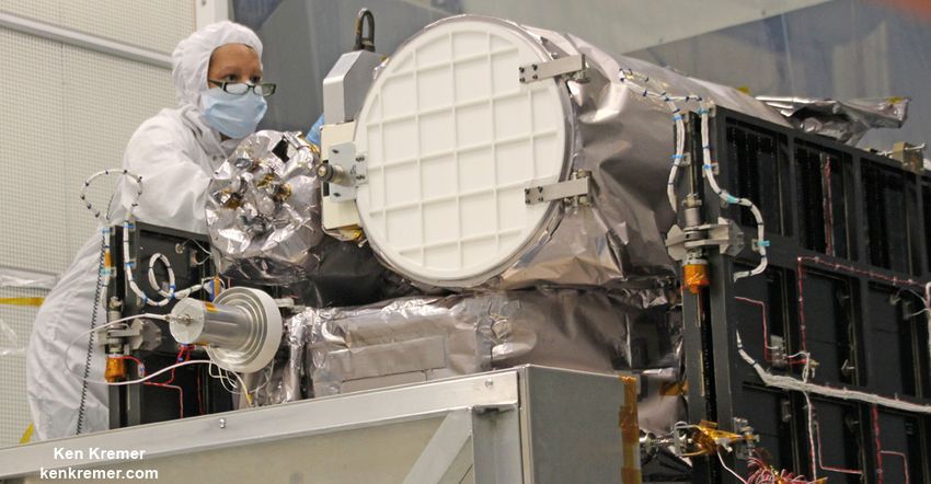
Space Systems                                                       Space Technologies Product Catalog

           Historical Timeline of SNC’s Space Systems
           Sierra Nevada Corporation is a privately held, woman-owned business that is building on its tradition of
           developing and providing electronics, avionics, and communications solutions with the addition of SNC’s Space
           Systems, in Louisville, Colorado. SNC’s Space Systems combines its acquisitions into a single entity, bringing
           together a complement of technical innovation and management expertise. A complete listing of SNC’s
           acquisitions can be found on SNC’s website.
           1963    Sierra Nevada Corporation (SNC) is founded by John Chisholm in Stead, Nevada.

           1981    Fatih Ozmen joins SNC as an engineering intern, completing his master’s thesis by focusing on the
                   company’s aviation and landing system projects.

           1988    Eren Ozmen joins SNC as a finance consultant shortly after receiving her MBA from the University of
                   Nevada, Reno.

           1994    Eren and Fatih Ozmen execute a management buy-out, becoming the sole owners of SNC as President
                   and CEO, respectively.

           1997    SpaceDev, Inc. is founded by Jim Benson, helping build the rocket engine that launched the world’s first
                   privately built manned spaceship into suborbital space.

           2001    Microsat Systems, Inc. (MSI) is formed by ITN Energy Systems in Littleton, Colorado.

           2006    SpaceDev acquires Starsys Research Corporation (SRC), a Colorado spacecraft subsystems company.

           2008    (January) SNC acquires MSI, then a leader in the small satellite market. MSI’s high-performance
                   spacecraft were known for providing small satellites with better payload mass fraction, power, and data
                   processing.

           2008    (December) SNC acquires SpaceDev, absorbing its Poway, California; Louisville, Colorado, and Durham,
                   North Carolina locations, adding tremendous space heritage to SNC with products that had flown on more
                   than 300 spacecraft for more than 20 years.

           2009    SNC forms its Space Systems business area, combining SpaceDev and Starsys Research Corp. with
                   MicroSat Systems and SNC’s existing space operations to create a single, comprehensive source for
                   development of advanced satellite, propulsion, and space vehicle systems, subsystems, and
                   components.

           2016    (January) SNC is competitively selected by NASA to receive a multi-year contract to provide cargo
                   delivery, return, and disposal services for the International Space Station (ISS).

           2016    SNC currently operates from 34 locations worldwide with a team of nearly 3,000 supporting its customers.
                   To date, SNC’s products have successfully supported more than 450 space missions.

                                                                                    Contact: SNC’s Space Systems, Space Technologies
                                                                           1722 Boxelder Street • Louisville, CO 80027 USA • 303-530-1925
                                                                                 www.sncspace.com/catalog • Email: ssg@sncorp.com
©2017 Sierra Nevada Corporation                                                                                                             2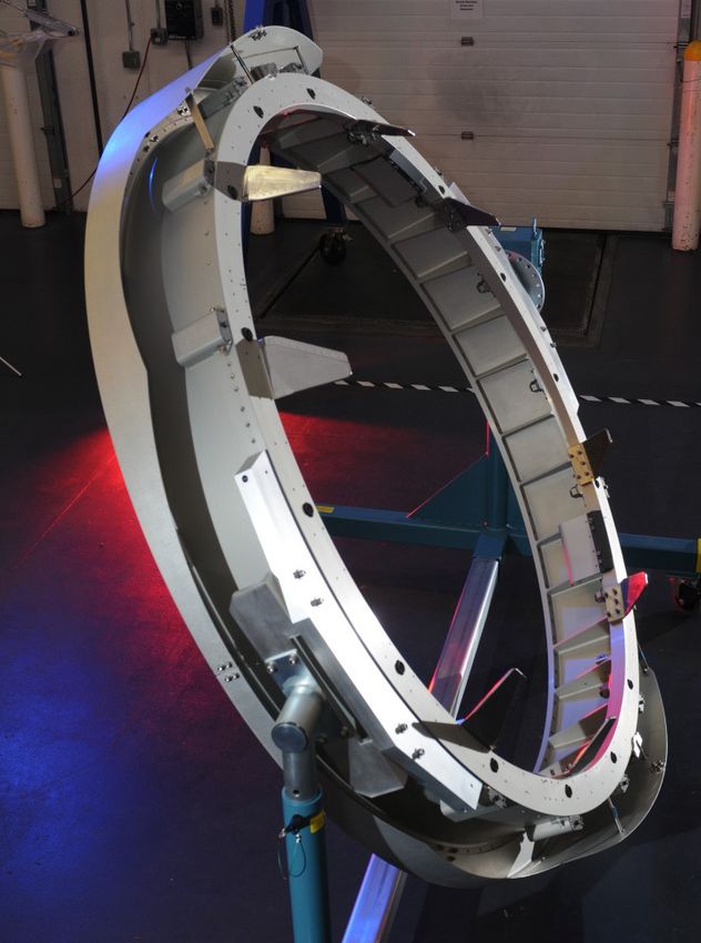
Space Systems                                                                  Space Technologies Product Catalog

           Space Technologies Expansive Exploration of Earth and our Planetary Solar System
           With more than 25 years of space heritage, SNC’s Space Systems has concluded more than 70 programs for
           NASA and more than 50 other clients. It has participated in more than 450 successful space missions through the
           delivery of more than 4,000 systems, subsystems, and components. SNC’s spacecraft components and
           subsystems have been on multiple interplanetary missions including the actuators and motors that power the
           Mars Rovers, and our hybrid rocket technologies that powered the first commercial spaceplane to suborbital
           space.
           SNC’s significant acquisitions and its impressive timeline of success position it for continued, unprecedented
           growth. The company holds great promise for the advancement of space and discovery in the future, in addition to
           improving the way we understand and observe our own planet, Earth.
           SNC is changing how we use space by building innovative, reliable, and lower-cost space transportation vehicles
           and satellites like Dream Chaser, TacSat-2, Trailblazer, and STPSat-5. Other products span the spectrum, giving
           SNC an extensive and impressive role in supporting defense, civil, international, and commercial programs. And
           we continue this long legacy of creating advanced space products such as avionics, solar arrays, and lightweight
           composite structures to benefit the spacecraft of the future.

          SNC’s Planetary Exploration. SNC has a significant presence in space with a long legacy of contribution to government, commercial, and
          civil customers on missions both near and far.

                                                                                               Contact: SNC’s Space Systems, Space Technologies
                                                                                      1722 Boxelder Street • Louisville, CO 80027 USA • 303-530-1925
                                                                                            www.sncspace.com/catalog • Email: ssg@sncorp.com
©2017 Sierra Nevada Corporation                                                                                                                        3
Space Systems                                                       Space Technologies Product Catalog

           Space Technologies Product Line
           SNC’s Space Systems was formed as a business area in
           early 2009 through the consolidation of SpaceDev, Inc.
           (including SpaceDev’s subsidiary Starsys Research) and
           MicroSat Systems, Inc. SNC is an industry leader in
           precision space mechanisms and complex spacecraft
           subsystems with an unmatched heritage of products
           including thousands of devices successfully flown on
           hundreds of spacecraft. SNC’s Space Systems has rapidly
           become a supplier of choice by offering an expansive
           portfolio of space-qualified products and subsystems that
           includes:
            •   Deployable Systems
            •   Docking and Berthing Systems
            •   Electrical Power Systems
            •   Flight and Thrust Vector Control Systems
            •   Launch Adapters and Separation Systems
            •   Mechanical and Structural Systems
            •   Pointing Systems and Motion Control
            •   Thermal Control Systems                                 Space Technologies Product Line Capabilities

           Facilities
           SNC’s Space Systems’ primary facility, located in
           Louisville, Colorado, just southeast of Boulder is an easy
           drive from Denver International Airport (DIA). It has more
           than 100,000 square feet of office and manufacturing
           space that is dedicated to spaceflight subsystem and
           component assembly and test, small satellite end-to-end
           production, and fabrication of SNC’s Dream Chaser multi-
           mission space utility vehicle. The facility features:
            •   AS9100 certification
            •   Precision temperature and humidity control
            •   ISO 8 modular production floor
            •   ISO 7 clean rooms
                                                                        Louisville, Colorado ISO 8 Modular Production Floor
            •   ISO 5 laminar flow benches
            •   Specialized equipment and tools for the handling,
                cleaning, assembly, and cleanliness-verification of
                optical-grade products
            •   End-to-end testing capabilities including vibration,
                shock, a rapid transition Thermal Test Chamber,
                radio frequency, thermal, thermal-vacuum and
                stiffness, as well as functional tests
            •   Large Area Pulsed Solar Simulator for solar array
                testing

                                                                        Louisville, Colorado Thermal and Vacuum Chambers

                                                                                     Contact: SNC’s Space Systems, Space Technologies
                                                                            1722 Boxelder Street • Louisville, CO 80027 USA • 303-530-1925
                                                                                  www.sncspace.com/catalog • Email: ssg@sncorp.com
©2017 Sierra Nevada Corporation                                                                                                              4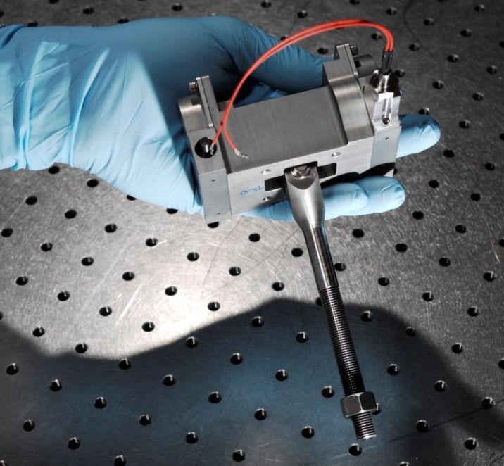
Space Systems                                                               Space Technologies Product Catalog

           At our Durham, North Carolina, location, SNC’s Space Systems employs a highly skilled team of experts who lead
           the aerospace industry in electromechanical motion control. The tenured team of engineers and technicians focus
           on the design, development, and production of spaceflight motors, actuators, and electromechanical devices with
           an unmatched, diverse product heritage. The Durham facility is located within minutes of the Raleigh-Durham
           International Airport and features:
            •   AS9100 certification
            •   ISO 8 modular production floor
            •   ISO 7 clean rooms
            •   ISO 5 laminar flow benches
            •   End-to-end testing capabilities including vibration, thermal, thermal-vacuum, stiffness, motor/actuator speed-
                torque-accuracy, line of sight micro-motion jitter testing, and functional testing

           The Durham and Louisville locations share personnel and facility resources to optimize program execution based
           on customer needs. Other facilities include a dedicated propulsion center (ORBITEC) located in Madison, WI, and
           local business development offices in Washington D.C.; Houston, Texas; Huntsville, Alabama; and Exploration
           Park, Florida.
           Test Simulator Capabilities
           SNC’s Space Systems Louisville location houses state-of-the-art production and test facilities, including the
           recently commissioned Large Area Pulsed Solar Simulator (LAPSS) that is used to verify solar array performance.
           The LAPSS, located in a large-scale testing zone, simulates the Sun to obtain accurate electrical performance
           measurements of solar panels.
           SNC’s LAPSS is capable of measuring panels that are 3.5 m x 3.5 m square with the AM0 (air mass zero)
           spectrum at a rate of 10 pulses per minute. The industry-standard LAPSS equipment was purchased from Alpha
           Omega Power Technologies—a well-known supplier of solar simulators to the space industry. In addition, SNC
           verifies all of its solar array systems using supplementary industry measurement standards and equipment
           provided by solar cell manufacturers such as SolAero Technologies, SpectroLab, and Azur Space.

                                                                                             LAPSS Test Area. SNC’s in-house LAPSS solar
                                                                                             array test area is used for secondary verification
           LAPSS Simulator. SNC’s LAPSS is capable of obtaining accurate performance
                                                                                             processes.
           measurements.

                                                                                            Contact: SNC’s Space Systems, Space Technologies
                                                                                   1722 Boxelder Street • Louisville, CO 80027 USA • 303-530-1925
                                                                                         www.sncspace.com/catalog • Email: ssg@sncorp.com
©2017 Sierra Nevada Corporation                                                                                                                     5
Space Systems                                                                  Space Technologies Product Catalog

           Engineering
           SNC’s Space Systems boasts a highly skilled team of industry experts who focus on a broad range of technical
           specialties. The engineering group’s breadth and depth of experience sets SNC apart from the competition,
           allowing it to thoroughly and efficiently respond to customer needs—both on production-type programs, as well as
           custom-engineered solutions. SNC’s talented personnel provide an array of engineering disciplines and tools
           summarized below:

            Disciplines
             • Mechanical Engineering                                      •     Electrical Engineering
             •      Structural Engineering                                 •     Systems Safety
             •      Systems Engineering                                    •     Manufacturing Engineering
             •      Thermal Engineering                                    •     Quality Assurance
             •      Radio Frequency Engineering                            •     Structural Analysis
             •      Guidance, Navigation, and Control Engineering          •     Reliability Assurance
             •      Thermal Analysis                                       •     Finite Element Modeling

            Tools
            CAD                                     AutoCAD                  SolidWorks                         Siemans NX
                                                 MSC Nastran         Nei Autodesk Nastran 2015                 NX Nastran 8.5
            Structural Analysis
                                                    NX CAE
            Thermal                             Thermal Desktop                SINDA G
            Numerical Analysis                      MATLAB                     Simulink                           Mathcad
            Electrical Simulations                   Pspice
            Electrical Design                        OrCAD
            Magnetic/Motor Analysis                  SPEED              Infolytica MotorSolve                 Infolytica Magnet
            Bearing Analysis                      Bearings 10+                   Cobra                            AB Jones
            Gear Analysis                      UTS Integrated Gear

                                                                                            Contact: SNC’s Space Systems, Space Technologies
                                                                                   1722 Boxelder Street • Louisville, CO 80027 USA • 303-530-1925
                                                                                         www.sncspace.com/catalog • Email: ssg@sncorp.com
©2017 Sierra Nevada Corporation                                                                                                                     6
Space Systems Deployable Systems
Deployable Systems
While many spacecraft are decreasing in size, physics will maintain the demand for large aperture subsystems.
For that reason, SNC considers deployable structures to be a critical element in the future of microsatellite
systems. Our Jackscrew boom system utilizes high-strength, high-stiffness articulated truss elements that ensure
low-risk linear deployment. The structure and deployment system is readily integrated into mass- and volume-
efficient super structures for planar arrays. Our K-truss booms are engineered with a strain-energy deployment
system that reduces cost and is constructed with a nonconductive material that enables antenna integration.
Catalog data sheets for the SNC’s Space Systems, Space Technologies Deployable Systems technology area
include:
• Jackscrew Deployed Boom
• K-truss Boom
Contact: SNC’s Space Systems, Space Technologies
1722 Boxelder Street • Louisville, CO 80027 USA • 303-530-1925
www.sncspace.com/catalog • Email: ssg@sncorp.com
©2017 Sierra Nevada Corporation 7Space Systems Jackscrew Deployed Boom
Jackscrew Deployed Boom
Design Description
Sierra Nevada Corporation’s (SNC) Space Systems
Jackscrew Deployed Boom, shown at right under test, is
a motor-deployed, high-stiffness and high-strength
articulated truss. The jackscrew boom deploys in a purely
linear/axial manner without the use of deployment
canisters for de-spin as required for motorized coilable
booms. Therefore, the jackscrew boom provides multiple
payload or cabling attachment points along the length of
the boom with a deadband-free, high mechanically
advantaged deployment without the parasitic mass of a
canister. The jackscrew drive system offers mass and
volume efficiency improvements over canister-deployed
booms. Jackscrew Deployed Boom Under Test
The jackscrew boom deployment method also provides
full structural integrity throughout deployment, thus allowing mid-deployment spacecraft maneuvering or other
loading without the risk of collapsing the boom. The jackscrew boom can be re-stowed after deployment by
reversal of the deployer motor.
The main components of the boom system, illustrated below, consist of the deployable boom assembly and the
deployer assembly. The deployer assembly uses a system of redundant belts driven by an electric motor to
synchronize and drive a series of jackscrews. The deployer also includes four structural tubes that position the
stowed boom and enclose the jackscrew drive shafts, a detent at each corner of the deployer, and four foldable
jackscrews.
Triangular cross-section booms are also available using three jackscrews. During deployment, the jackscrews
(aka elevator screws) and deployment detent work together to sequentially expand and form each bay of the
boom as it is deployed. At least one batten frame of the boom is engaged with the jackscrews at any point in time
during deployment providing full structural integrity throughout deployment. The deployer jackscrews are
restrained in their folded, stowed configuration during launch and prior to boom deployment. Following a signal to
initiate deployment, the jackscrews are released and transition to their deployed, locked configuration. A
brushless dc motor provides power to the system and limit switches identify first motion and successful
deployment of the boom.
10-Bay Jackscrew Deployed Boom (stowed) Deployed Boom Cantilevered with 11-lb Tip Mass (no offloading)
Contact: SNC’s Space Systems, Space Technologies
1722 Boxelder Street • Louisville, CO 80027 USA • 303-530-1925
www.sncspace.com/catalog • Email: ssg@sncorp.com
©2017 Sierra Nevada Corporation Export Controlled Under Export Administration Regulations (EAR) 8Space Systems Jackscrew Deployed Boom
Features
• Purely linear/axial deployment • High-force deployment/retraction
• Highly tailorable for thermal stability, strength, and stiffness • Highly scalable and mass optimized
• Simple, high-reliability, high-tension deployment • Full stiffness and strength during deployment
• Exposed payload interfaces throughout deployment and
during pre-flight integration
Applications
• Solar array and solar-sail deployment and retraction • Instrument deployment and retraction
• Antenna deployment/retraction • Gravity gradient mass deployment and retraction
• Synthetic Aperture Radar (SAR) deployment and retraction • Spacecraft separation
Product Specifications for a 10-Bay Jackscrew Boom
• Dimensions: 190-in long x 15.5-in • 1st Bending Mode: 6.9 Hz • Tip Torsion Stiffness: 13,594
diameter in-lb/rad
• Mass: 11.7 lb • 1st Torsion Mode: 16.4 Hz • Tip Shear Stiffness: 25 lb/in
Contact: SNC’s Space Systems, Space Technologies
1722 Boxelder Street • Louisville, CO 80027 USA • 303-530-1925
www.sncspace.com/catalog • Email: ssg@sncorp.com
©2017 Sierra Nevada Corporation Export Controlled Under Export Administration Regulations (EAR) 9Space Systems K-truss Boom
K-truss Boom
Design Description
Sierra Nevada Corporation’s (SNC) Space Systems
K-truss Boom is an elastically deployed boom which
utilizes stowed energy for deployment. The K-truss boom
deploys in a purely linear/axial manner unlike a
conventional lanyard deployed coilable boom. Therefore
the K-truss boom provides multiple payload or cabling
attachment points to allow the deployment of objects
along the length of the boom before, during, and after
deployment.
This type of boom simplifies deployable structures on
small satellites by eliminating the need for a drive motor
and electronics. The resulting boom provides a
nonrotating deployment with unprecedented thermal K-truss Boom with Quadrifilar Helical Antenna Under Test
stability, precision, and repeatability, in addition to high stiffness and high strength. This type of deployed structure
is also applicable to many spacecraft that have been traditionally limited to fiberglass coilable type booms. This
enabling boom technology can increase satellite application capabilities, improve reliability, and reduce costs. The
stowed and deployed K-truss boom is illustrated below.
Features
• Exposed payload interfaces throughout deployment and • Nonconductive/magnetically “clean” materials available for
during pre-flight integration integrated antennae or magnetometers
• Highly tailorable for thermal stability, strength, and • Highly scalable and mass optimized
stiffness
• Predictable deployment behavior • Zero deadband monolithic structure
• Elastically deployed “tape” joints eliminate motorized • Precision deployment and pointing accuracy of the payload
actuation mass
Applications
• Solar array/solar-sail deployment • Attitude control thrusters • Gravity gradient mass deployment
• Antenna deployment • Instrument deployment • Magnetometer deployment
Product Specifications*
• Dimensions: 101.5-inch long x 9.5-inch diameter • 1st Bending Mode: 3.5 Hz
• System Mass:Space Systems Docking and Berthing Systems
Docking and Berthing Systems
Sierra Nevada Corporation (SNC) Space Systems solidified our docking and berthing technology by being a
major subcontractor on the Orbital Express program, providing the system that captured and docked two
spacecraft together on-orbit to allow for remote servicing such as refueling and replacement of outdated and
expended components. We were then leveraged this mechanical systems experience into becoming the go-to
supplier for the industry standard Passive Common Berthing Mechanism (PCBM), required for spacecraft such as
the Orbital Cygnus Advanced Maneuvering Vehicle and the Bigelow Expandable Activity Module (BEAM) to berth
with the International Space Station (ISS).
Catalog data sheets for SNC’s Space Systems, Space Technologies Docking and Berthing Systems technology
area include:
• Passive Common Berthing Mechanism (PCBM)
Contact: SNC’s Space Systems, Space Technologies
1722 Boxelder Street • Louisville, CO 80027 USA • 303-530-1925
www.sncspace.com/catalog • Email: ssg@sncorp.com
©2017 Sierra Nevada Corporation 11Space Systems Passive Common Berthing Mechanism
Passive Common Berthing Mechanism
(PCBM)
Design Description
Sierra Nevada Corporation’s (SNC) Space Systems has
become the go-to supplier for the Passive Common
Berthing Mechanism (PCBM), an industry standard
mechanical and structural interface required to safely and
reliably berth commercial or government spacecraft to the
International Space Station (ISS).
SNC’s PCBM is a flight-proven system that allows
alignment and environmental sealing between the ISS and
pressurized vehicles. It is a fully passive assembly (active
side permanently attached to the Space Station) with
minimal moving parts.
SNC’s PCBM has been vetted and approved by NASA for
compliance to the strict human-rating standards and
pedigree that is required for International Space Station
(ISS) applications. It has been fully tested to ensure
compliance with functional performance and sealed
interface requirements.
After delivery, SNC provides additional services to
integrate the PCBM onto the vehicle and leak check the
interface seals, as well as support NASA FE-1410
pressurized leak testing of the PCBM’s Active Common
Berthing Mechanism (ACBM) interface.
Passive Common Berthing Mechanism (PCBM)
Features
• Fully tested and verified powered bolt nut assemblies • Alignment pin socket assemblies provide fine alignment and
(PNA), the main functional interface of the PCBM take shear loads between the PCBM and ACBM
• Thermal standoff assemblies maintain pre-load between • Capture fittings provide an interface for the ACBM to grab and
the PCBM and the Active CBM (ACBM) on the ISS pull the PCBM to berth
• Skirt segment assemblies shield the PCBM from • Alignment guide assemblies provide gross alignment and
micrometeoroid debris clocking of the PCBM to the ACBM
• Positive grounding paths to main PCBM structure
Applications
• Berthing to the ISS for commercial or government customer missions
Heritage Programs
• Orbital ATK Cygnus Cargo Resupply Service (CRS) • Cygnus Orb-4 – flown December 2015
• Cygnus CRS Orb-1 and Orb-2 • Cygnus CRS Orb-5 through Orb-8 flight systems delivered to
customer
• Cygnus CRS Orb-3 (vehicle lost during launch) • Bigelow Expandable Activity Module (BEAM) flight system
delivered to customer
Contact: SNC’s Space Systems, Space Technologies
1722 Boxelder Street • Louisville, CO 80027 USA • 303-530-1925
www.sncspace.com/catalog • Email: ssg@sncorp.com
©2017 Sierra Nevada Corporation Export Controlled Under Export Administration Regulations (EAR) 12Space Systems Passive Common Berthing Mechanism
PCBM Used for Bigelow Expandable Activity Module (BEAM)
PCBM Test Fixtures. SNC’s PCBM Lift Fixture (shown above at left) used to move the ring during AI&T and PCBM Rotation Fixture
(shown at right), proof loaded at two times over expected maximum mass.
PCBM During In-flight Mate with ACBM and Drawing of Common Berthing Mechanism Subsystems
Contact: SNC’s Space Systems, Space Technologies
1722 Boxelder Street • Louisville, CO 80027 USA • 303-530-1925
www.sncspace.com/catalog • Email: ssg@sncorp.com
©2017 Sierra Nevada Corporation Export Controlled Under Export Administration Regulations (EAR) 13Space Systems Electrical Power Systems
Electrical Power Systems
Sierra Nevada Corporation (SNC) Space Systems provides highly scalable power systems with power ranges
from 10 W to 10 kW. SNC offers end-to-end electric power systems (EPS) consisting of fully assembled and
tested solar arrays, solar array drives, slip rings, hinges, hold down mechanisms, power electronics, batteries,
and motor control electronics. Our engineering teams have the expertise and experience to define, analyze, and
test complete power systems utilizing state-of-the-art tools and integration equipment. Our heritage and scalable
power systems can be tailored to fit a wide variety of mission options with reduced cost and risk by incorporating
existing qualified and flight-proven designs. SNC has heritage EPS designs ranging from 28 V to 125 V, with
power from 500 W to 3,000 W.
Industry-First Innovation
SNC has developed an automated solar array manufacturing process utilizing Surface Mount Technology (SMT)
to significantly reduce the cost of space power. This technology enables an unprecedented improvement in watts-
per-area, reliability, and solar array lead time. SNC’s team of engineers, along with strategic industry partners,
has developed an all-back-side-contact solar cell that enables solar array assembly through a standard pick-and-
place operation. This technology results in a zero-touch labor solution and a significant improvement in overall
solar array performance.
SNC has conducted significant environmental and electrical testing on this new technology and will fly a
demonstration mission in December 2016. Qualification testing will continue through 2017 to further demonstrate
the significant benefits achieved by this patent-pending innovation that promises to drastically change the way
electrical power is generated for a spacecraft.
Catalog data sheets for SNC’s Space Systems, Space Technologies Electrical Power Systems technology area
include:
• C14-750 W Solar Array Drive Assembly (SADA) (See Pointing Systems and Motion Control section)
• Cell Shorting Device (CSD) Battery Switch
• Cubesat Solar Array
• Microsat Articulated Solar Array System
• Microsat Rigid Panel Solar Array System
• Smallsat Solar Array System
• T25 Incremental Rotary Actuator (See Pointing Systems and Motion Control section)
Contact: SNC’s Space Systems, Space Technologies
1722 Boxelder Street • Louisville, CO 80027 USA • 303-530-1925
www.sncspace.com/catalog • Email: ssg@sncorp.com
©2017 Sierra Nevada Corporation 14Space Systems Cell Shorting Device Battery Switch
Cell Shorting Device (CSD) Battery Switch
Design Description
Sierra Nevada Corporation’s (SNC) Space Systems Cell
Shorting Device (CSD) Battery Switch is a robust,
spaceflight-proven mechanism that passively removes a
cell from a spacecraft battery’s electrical circuit. The CSD
shorts across the cell terminals once the cell begins to fail
(or has failed) and voltage has been driven into reversal.
The device is a mechanical switch that closes when a
spring-loaded latch is released by a small paraffin
actuator. Different from standard SNC actuators, which
use a heater to melt the paraffin, the CSD actuator uses
diodes directly attached to the actuator body. Since the Cell Shorting Device (CSD) Battery Switch
diodes only allow current to flow in one direction, during
normal operation no current flows through the CSD. When the cell goes into voltage reversal, current is allowed to
flow through the CSD and the diodes. As the current level increases, the temperature of the diodes increases and
melts the paraffin. The expanding paraffin extends the actuator output shaft, which releases the latch mechanism
after a period of 10 seconds to 1 minute (depending on temperature and current level). Once the latch is released,
a compression spring drives a wedge contact between the two fixed contacts, closing the circuit and shorting the
cell across the terminals.
Initially designed to attach directly to the terminals, the mounting options for the CSD can be changed depending
on the cell configuration and customer requirements. The CSD works on both Ni-H2 and Li-ion batteries.
Features
• Mounting interface easily configurable • Simple, high-reliability operation
• Passive operation requires no control electronics • Small size and low-mass package
Note: All dimensions above are in inches.
Contact: SNC’s Space Systems, Space Technologies
1722 Boxelder Street • Louisville, CO 80027 USA • 303-530-1925
www.sncspace.com/catalog • Email: ssg@sncorp.com
©2017 Sierra Nevada Corporation Export Controlled Under Export Administration Regulations (EAR) 15Space Systems Cell Shorting Device Battery Switch
Applications
• Spacecraft battery cells that require a safe cell battery switch to bypass or remove faulty cells that fail or begin to fail
Heritage Programs
• Amazonas 3 (an Hispasat group of • Intermediate Circular Orbit (ICO) • Satmex 6 and 8 (Satélites
Spanish communication satellites) communications satellite Mexicanos)
• Anik G1 (a fixed satellite services • Intelsat 14, 17, 19, and 20 • SES Sirius 5 (a Society of European
multi-mission satellite; Telesat, (International Telecommunications Satellites)
Canada) communication satellites)
• AsiaSat 5 and 7 (Chinese • iPSTAR (a Thailand geostationary • Spainsat (Spanish Ministry of
communication satellites) communications satellite) Defense communications satellite)
• DirecTV-9 (U.S. geostationary • Jupiter (Hughes Network Systems, • Superbird 7 (a Japanese
communications satellite) U.S. communications satellite) communications satellite)
• EchoStar XI, XIV, XV, • New Skies Satellites (NSS) 12 and • Telstar 11N and 14R
and XVI (U.S. communications 14 (now SES World Skies; Dutch (broad Ku-band communications
satellites) communications satellites) satellites Telesat, Canada)
• Galaxy 16, 18, and 19 • Nimiq 5 and 6 (Telesat, Canada • XM5 (a digital audio radio service
(U.S. communications satellites) communications satellites) satellite)
• Hispasat 1E (a Spanish • QuetzSat (a Mexican geostationary
communications satellite) communications satellite)
Product Specifications
U.S. SI
Mechanical
Envelope dimensions 1.85 in x 3.26 in x 0.63 in 4.69 cm x 8.27 cm x 1.59 cm
Mass < 2.3 oz < 65 grams
Life cycles Single on-orbit operation
Operation time (with 60 A @ ambient temp/pressure) ~ 25 s
Electrical
Forward voltage drop, Vf (@ 100 A, 300 µsec pulse) < 0.65 Vdc
Reverse leakage current, Ir (@ 30 Vdc) < 30 mA
Case insulation (@ 250 Vdc) > 100 MΩ
Closed circuit resistance (@ 60 A, ambient temp/pressure) < 0.54 mΩ
Switch may activate voltage (@ 95 A) > 0.16 Vdc but < 0.70 Vdc
Switch must activate current ≥ 20 A
Fuse no blow Continuously @ 110 A
Fuse must blow < 1 s @ 1,300 A; < 0.1 s @ 2,500 A
Thermal
Operating temperatures +14 °F to +113 °F
Nonoperating temperatures -13 °F to +167 °F
Paraffin non-op temp (standard) +176 °F
History
More than 100 million hours on-orbit (through May 2013) More than 2,900 units on 42 spacecraft (through May 2013)
Note: This data is for information only and subject to change. Contact SNC’s Space Systems, Space Technologies for design data.
Contact: SNC’s Space Systems, Space Technologies
1722 Boxelder Street • Louisville, CO 80027 USA • 303-530-1925
www.sncspace.com/catalog • Email: ssg@sncorp.com
©2017 Sierra Nevada Corporation Export Controlled Under Export Administration Regulations (EAR) 16Space Systems Cubesat Solar Array System
Cubesat Solar Array System—13 W Surface
Mount Technology
Design Description
Sierra Nevada Corporation’s (SNC) Space Systems
13 W Surface Mount Technology (SMT) Solar Array
System provides highly scalable satellite power systems
with power ranges from 10 W to 10 kW. SNC offers
end-to-end electric power solutions that consist of fully
assembled and tested solar array wings, solar array
drives, slip rings, power control and distribution
electronics, batteries, and motor control electronics in a SHARC Program for the 5U Cubesat Small Satellite. This
wide variety of configurations to meet various mission program used our Cubesat Solar Array System. Credit: AFRL
requirements. SNC has provided systems, subsystems,
and components on more than 450 space missions.
SNC’s team of experts developed a new, patent-pending, manufacturing technology that automates cell laydown
and assembly of the solar array. This new technology offers several advantages over the conventional
manufacturing approach including increased watts per area, increased watts per kilogram, and lower dollars per
watt. SNC has teamed with an innovative photovoltaic solar cell manufacturing company to create an industry first
all-back-side-contact solar cell that enables automated assembly through standard electronics manufacturing
techniques (surface mount pick-and-place technology). This process eliminates all touch labor associated with
assembling a solar array and has drastically reduced cost and significantly improved reliability.
SNC’s approach also reduces the design
labor content associated with producing a
solar array. Complex cell stringing, laydown,
diode board, return board, and interconnect
wiring have all been replaced by one Printed
Circuit Board (PCB) drawing. Engineering
SHARC Solar Array drawings associated with templates, tooling, fixturing, and other manufacturing aids
have been completely eliminated. This reduction in nonrecurring engineering (NRE)
allows SNC to design, fabricate, inspect, and test a complete solar array 3 to 6 months from contract award,
resulting in significant mission benefit. The solar array is no longer a pacing item on the program and late design
changes in power requirements can be easily incorporated.
SNC was contracted to provide the solar array for the AFRL Satellite for High Accuracy Radar Calibration
(SHARC) program on May 26, 2016. SNC delivered a fully integrated and tested solar array to AFRL on July 26,
2016; a total program duration of 2 months. The SHARC solar array is a 5U cubesat array that generates
approximately 13 W at the Beginning of Life (BOL). By utilizing SNC’s technology, the SHARC program benefited
from a 45 percent increase in total spacecraft power due to the exceptional packing factor of the solar cell
geometry. With this small cell size, SNC significantly increases the overall cell packing factor which dramatically
improves the total watts per area on a given panel size. The SHARC program is scheduled for launch to the
International Space Station (ISS) in late 2016 with an expected deployment in the first quarter of 2017.
Dimensions
Note: All dimensions above are in inches.
Contact: SNC’s Space Systems, Space Technologies
1722 Boxelder Street • Louisville, CO 80027 USA • 303-530-1925
www.sncspace.com/catalog • Email: ssg@sncorp.com
©2017 Sierra Nevada Corporation Export Controlled Under Export Administration Regulations (EAR) 17Space Systems Cubesat Solar Array System
Features
• Scalable power system with best-in-class watts/area • High-efficiency 3J Gallium Arsenide cells
• Very short lead time from design to delivery • Low mass
• Zero touch labor • Low-cost automated assembly
• Low NRE through automation • High reliability (no touch labor)
Applications
• Low-cost, highly scalable satellite power systems • Custom power systems with ranges from 10 W to 10 kW
Heritage Programs
• High Accuracy Radar Calibration (SHARC) program
Product Specifications
U.S. SI
Mechanical
Envelope dimensions 22.2 in x 3.4 in 564 mm x 86.4 mm
Mass .39 lb .175 kg
Life cycles 5,000 thermal cycles
Coverglass Proprietary
Substrates Printed Circuit Board
Temperature sensors 1
Electrical
Cell type Triple Junction Gallium Arsenide
Number of strings 61
Number of cells per string 5 cells in series
Number of panels 1
Power End of Life (BOL) 13 W
Cell efficiency Beginning of Life (BOL) 30%
Voltage open circuit (Voc) @ 28 C BOL 13.2 V per section
Current under short circuit (Isc) @ 28 C BOL .40 A per section
Voltage maximum power (Vmp) @ 28 C BOL 11.7 V per section
Current at maximum power (Imp ) @ 28 C BOL .40 A per section
Maximum power (Pmax) @ 28 C BOL 4.4 W per section
Thermal
Test temperature range -166 °F to +288 °F -110 °C to +142 °C
Note: This data is for information only and subject to change. Contact SNC’s Space Systems, Space Technologies for design data.
Contact: SNC’s Space Systems, Space Technologies
1722 Boxelder Street • Louisville, CO 80027 USA • 303-530-1925
www.sncspace.com/catalog • Email: ssg@sncorp.com
©2017 Sierra Nevada Corporation Export Controlled Under Export Administration Regulations (EAR) 18Space Systems Microsat Articulated Solar Array System
Microsat Articulated Solar Array System—
400 W Articulated Array
Design Description
Sierra Nevada Corporation’s (SNC) Space Systems
provides highly scalable satellite power systems with
power ranges from 10 W to 10 kW. Providing end-to-end
electric power solutions, SNC’s systems consist of fully
assembled and tested solar array wings, solar array
drives, slip rings, power control and distribution
electronics, batteries, and motor control electronics in a
wide variety of configurations to meet various mission STPSat-5 Spacecraft Uses SNC’s Articulated Array System
requirements. With a long and successful heritage, SNC
has provided systems, subsystems, and components on more than 450 space missions. More recently, SNC has
developed, qualified, and manufactured the solar arrays for the STPSat-5 mission. Each wing consists of two
deployable panels for a total power generation of 414 W at the Beginning of Life (BOL).
SNC experts conducted solar cell stringing and laydown for the STPSat-5 panels. Coverglass interconnected cells
(CIC) were purchased from a heritage space solar cell manufacturer and integrated on to the panels entirely by
SNC. Front and backside wire harness was also integrated at SNC
offering a turnkey solution to the end customer. In addition, SNC has
the capability to perform cell laydown from any solar cell provider. This
capability allows SNC to be cell agnostic when it comes to developing
the overall power system resulting in a lower cost, reliable delivery
schedule, and the best technical solution to the end customer.
The substrate panels are a typical construction of M55J/EX1515 face
sheets bonded to a low-density 5056 aluminum perforated
honeycomb core with a Kapton cover for the cell installation surface.
STPSat-5 Panel The STPSat-5 spacecraft consists of two deployable wings with two
panels each for a total of four panels per spacecraft. Each panel
measures approximately 20 inches by 28 inches. Two hold down and release mechanisms (HDRM) restrain each
wing in the stowed condition through cup and cone shear features that are incorporated into each panel.
Following release, spring-driven hinges with integral dampers passively extend the array in a controlled and
predictable fashion. Each solar array wing stows completely within the allowable envelope with a predicted
stowed first mode frequency of 53 Hz and a deployed frequency of 3 Hz.
Dimensions
Deployed Stowed
Note: All dimensions above are in inches.
Contact: SNC’s Space Systems, Space Technologies
1722 Boxelder Street • Louisville, CO 80027 USA • 303-530-1925
www.sncspace.com/catalog • Email: ssg@sncorp.com
©2017 Sierra Nevada Corporation Export Controlled Under Export Administration Regulations (EAR) 19Space Systems Microsat Articulated Solar Array System
Features
• Scalable power system based on existing design • High-efficiency Gallium Arsenide cells
• Complete power system solution • Low mass
• High-reliability solar cells • Customizable
• Heritage flight-proven design minimizes • Heritage mechanisms
nonrecurring engineering (NRE)
Applications
• Low-cost, highly scalable satellite power systems • Custom power systems with ranges from 100 W to 10 kW
Heritage Programs
• ORBCOMM Generation 2 (OG2) • Tactical Satellite (TacSat-2)
• Demonstration and Science Experiment (DSX) • Space Test Program Satellite (STPSat-5) (ongoing)
Product Specifications
U.S. SI
Mechanical
Envelope dimensions (deployed) 50.6 in x 27.9 in 1,285 mm x 706 mm
Envelope dimensions (stowed) 23.6 in x 27.9 in 600 mm x 706 mm
Mass (with Yoke) per wing 8.2 lb 3.7 kg
Life cycles 12,000 thermal cycles
Coverglass Qioptiq 4 mil CMG/AR
Substrates M55J 7.5 mil facesheets, .390-inch perforated core, 2 mil Kapton
Temperature sensors None
Electrical
Cell type Triple Junction Gallium Arsenide
Number of strings 20
Number of cells per string 18 cells in series
Number of panels 4
Power End of Life (BOL) 414 W
Cell efficiency Beginning of Life (BOL) 29.3%
Voltage open circuit (Voc) @ 28 C BOL 47.5 V per section
Current under short circuit (Isc) @ 28 C BOL 1.5 A per section
Voltage maximum power (Vmp) @ 28 C BOL 42.5 V per section
Current at maximum power (Imp ) @ 28 C BOL 1.5 A per section
Maximum power (Pmax) @ 28 C BOL 62.1 W per section
Thermal
Test temperature range -166 °F to +288 °F -110 °C to +142 °C
Note: This data is for information only and subject to change. Contact SNC’s Space Systems, Space Technologies for design data.
Contact: SNC’s Space Systems, Space Technologies
1722 Boxelder Street • Louisville, CO 80027 USA • 303-530-1925
www.sncspace.com/catalog • Email: ssg@sncorp.com
©2017 Sierra Nevada Corporation Export Controlled Under Export Administration Regulations (EAR) 20Space Systems Microsat Rigid Panel Solar Array System
Microsat Rigid Panel Solar Array System—
250 W Deployable Array
Design Description
Sierra Nevada Corporation’s (SNC) Space Systems
provides highly scalable satellite power systems with
power ranges from 10 W to 10 kW. Providing end-to-end
electric power solutions, SNC’s systems consists of fully
assembled and tested solar array wings, solar array drives,
slip rings, power control and distribution electronics,
batteries, and motor control electronics in a wide variety of
configurations to meet various mission requirements. With The CYGNSS Spacecraft Uses SNC’s Deployable Rigid
a long and successful heritage, SNC has provided Panel Solar Array System Credit: NASA
systems, subsystems, and components on more than 450
space missions. More recently, SNC’s team of experts have developed, qualified, and delivered eight solar array
assemblies capable of delivering 267 W each at the Beginning of Life (BOL) to NASA Langley for the Cyclone
Global Navigation Satellite System (CYGNSS) hurricane forecasting constellation.
The SNC solar array design utilizes industry standard high-efficiency triple-junction
solar cells with extensive flight heritage. SNC’s in-house experts build upon this flight
heritage or develop new design or customized new systems to meet customer-specific
requirements and mission constraints. Our power engineers have developed
standardized tools and processes for performing rapid power analysis while
incorporating detailed thermal and radiation models. SNC incorporates multiple solar
cell sizes and suppliers to reduce the overall recurring cost of solar power. For each
NASA CYGNSS spacecraft, the solar assembly consists of four body-mounted panels
and two deployable wings for a total of eight panels per spacecraft. Each panel
measures approximately 9 inches by 20 inches. These substrate panels are a typical
construction of M55J/EX1515 face sheets bonded to a low-density 5056 aluminum
Stowed CYGNSS Wing perforated honeycomb core with a Kapton cover for the cell installation surface. One
hold down and release mechanism (HDRM) restrains each wing in the stowed
condition through cup/cone shear features that are incorporated into each panel. Following release, spring-driven
hinges passively extend the array into the fully deployed configuration. Each solar array wing stows completely
within the allowable envelope with a predicted stowed first mode frequency of 312 Hz and a deployed frequency
of 6.68 Hz.
SNC performs in-house random and sine vibration, thermal vacuum, and thermal cycle testing. Our engineers
subjected the CYGNSS array to rigorous in-house environmental, deployment, and electrical testing. In addition,
SNC has the capability in-house to perform Large Area Pulsed Solar Simulator (LAPSS) testing on a variety of
panel sizes.
Dimensions
Note: All dimensions above are in inches.
Contact: SNC’s Space Systems, Space Technologies
1722 Boxelder Street • Louisville, CO 80027 USA • 303-530-1925
www.sncspace.com/catalog • Email: ssg@sncorp.com
©2017 Sierra Nevada Corporation Export Controlled Under Export Administration Regulations (EAR) 21You can also read