Io IP - Installation and Operation Manual - Transport, Capture, Display - AJA Video
←
→
Page content transcription
If your browser does not render page correctly, please read the page content below
                                    Io IP
                           Transport, Capture, Display

            Installation and Operation Manual

Version 16.0r1
Published March 19, 2021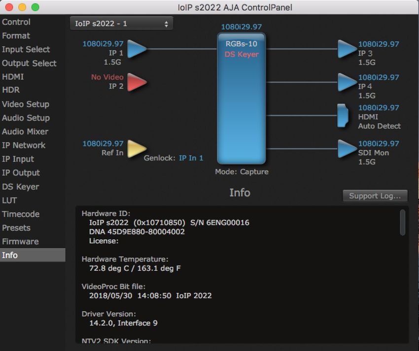
    Notices
                   Trademarks
                        AJA® and Because it matters.® are registered trademarks of AJA Video Systems, Inc.
                        for use with most AJA products. AJA™ is a trademark of AJA Video Systems, Inc. for
                        use with recorder, router, software and camera products. Because it matters.™ is a
                        trademark of AJA Video Systems, Inc. for use with camera products.
                        Corvid Ultra®, lo®, Ki Pro®, KONA®, KUMO®, ROI® and T-Tap® are registered trademarks of
                        AJA Video Systems, Inc.
                        AJA Control Room™, KiStor™, Science of the Beautiful™, TruScale™, V2Analog™ and
                        V2Digital™ are trademarks of AJA Video Systems, Inc.
                        All other trademarks are the property of their respective owners.

                   Copyright
                        Copyright © 2021 AJA Video Systems, Inc. All rights reserved. All information in
                        this manual is subject to change without notice. No part of the document may be
                        reproduced or transmitted in any form, or by any means, electronic or mechanical,
                        including photocopying or recording, without the express written permission of AJA
                        Video Systems, Inc.

                   Contacting AJA Support
                        When calling for support, have all information at hand prior to calling. To contact AJA
                        for sales or support, use any of the following methods:

                          Telephone          +1.530.271.3190
                          FAX                +1.530.271.3140
                          Web                https://www.aja.com
                          Support Email      support@aja.com
                          Sales Email        sales@aja.com

Io IP Transport, Capture, Display v16.0r1                               2                                         www.aja.com
Contents
           Notices  .  .  .  .  .  .  .  .  .  .  .  .  .  .  .  .  .  .  .  .  .  .  .  .  .  .  .  .  .  .  .  .  .  .  .  .  .  .  2
                  Trademarks .  .  .  .  .  .  .  .  .  .  .  .  .  .  .  .  .  .  .  .  .  .  .  .  .  .  .  .  .  .  .  .  .  .  .  .  .  .  .  .  .  .  .  2
                  Copyright  .  .  .  .  .  .  .  .  .  .  .  .  .  .  .  .  .  .  .  .  .  .  .  .  .  .  .  .  .  .  .  .  .  .  .  .  .  .  .  .  .  .  .  .  2
                  Contacting AJA Support .  .  .  .  .  .  .  .  .  .  .  .  .  .  .  .  .  .  .  .  .  .  .  .  .  .  .  .  .  .  .  .  .  .  .  2

           Chapter 1 – Introduction .  .  .  .  .  .  .  .  .  .  .  .  .  .  .  .  .  .  .  .  .  .  .  .  .  .  .  5
                  Overview .  .  .  .  .  .  .  .  .  .  .  .  .  .  .  .  .  .  .  .  .  .  .  .  .  .  .  .  .  .  .  .  .  .  .  .  .  .  .  .  .  .  .  .  . 5
                  Io IP Features .  .  .  .  .  .  .  .  .  .  .  .  .  .  .  .  .  .  .  .  .  .  .  .  .  .  .  .  .  .  .  .  .  .  .  .  .  .  .  .  .  .  5
                     AJA Software & Utilities  .  .  .  .  .  .  .  .  .  .  .  .  .  .  .  .  .  .  .  .  .  .  .  .  .  .  .  .  .  .  .  .  .  . 7
                  Network Requirements .  .  .  .  .  .  .  .  .  .  .  .  .  .  .  .  .  .  .  .  .  .  .  .  .  .  .  .  .  .  .  .  .  .  .  . 8
                  System Requirements .  .  .  .  .  .  .  .  .  .  .  .  .  .  .  .  .  .  .  .  .  .  .  .  .  .  .  .  .  .  .  .  .  .  .  .  . 8
                     Disk Storage Methods  .  .  .  .  .  .  .  .  .  .  .  .  .  .  .  .  .  .  .  .  .  .  .  .  .  .  .  .  .  .  .  .  .  .  . 9
                  Hardware Description  .  .  .  .  .  .  .  .  .  .  .  .  .  .  .  .  .  .  .  .  .  .  .  .  .  .  .  .  .  .  .  .  .  .  .  .  9
                     Front Panel Controls and Indicators .  .  .  .  .  .  .  .  .  .  .  .  .  .  .  .  .  .  .  .  .  .  .  .  .  .  9
                     Rear Panel Connectors  .  .  .  .  .  .  .  .  .  .  .  .  .  .  .  .  .  .  .  .  .  .  .  .  .  .  .  .  .  .  .  .  .  .10
                  In This Manual  .  .  .  .  .  .  .  .  .  .  .  .  .  .  .  .  .  .  .  .  .  .  .  .  .  .  .  .  .  .  .  .  .  .  .  .  .  .  .  .  . 11

           Chapter 2 – Installation .  .  .  .  .  .  .  .  .  .  .  .  .  .  .  .  .  .  .  .  .  .  .  .  .  .  .  13
                  Installation Overview .  .  .  .  .  .  .  .  .  .  .  .  .  .  .  .  .  .  .  .  .  .  .  .  .  .  .  .  .  .  .  .  .  .  .  .  .13
                  Unpacking  .  .  .  .  .  .  .  .  .  .  .  .  .  .  .  .  .  .  .  .  .  .  .  .  .  .  .  .  .  .  .  .  .  .  .  .  .  .  .  .  .  .  . 13
                     Shipping Box Contents .  .  .  .  .  .  .  .  .  .  .  .  .  .  .  .  .  .  .  .  .  .  .  .  .  .  .  .  .  .  .  .  .  .13
                  Installing Io IP Software  .  .  .  .  .  .  .  .  .  .  .  .  .  .  .  .  .  .  .  .  .  .  .  .  .  .  .  .  .  .  .  .  .  .  .13
                     NMOS Installation  .  .  .  .  .  .  .  .  .  .  .  .  .  .  .  .  .  .  .  .  .  .  .  .  .  .  .  .  .  .  .  .  .  .  .  .  .14
                     macOS Installations .  .  .  .  .  .  .  .  .  .  .  .  .  .  .  .  .  .  .  .  .  .  .  .  .  .  .  .  .  .  .  .  .  .  .  .14
                     Io IP Firmware Installation .  .  .  .  .  .  .  .  .  .  .  .  .  .  .  .  .  .  .  .  .  .  .  .  .  .  .  .  .  .  .  .14
                  Cabling the System .  .  .  .  .  .  .  .  .  .  .  .  .  .  .  .  .  .  .  .  .  .  .  .  .  .  .  .  .  .  .  .  .  .  .  .  .  .14
                     Io IP Cable Connections .  .  .  .  .  .  .  .  .  .  .  .  .  .  .  .  .  .  .  .  .  .  .  .  .  .  .  .  .  .  .  .  . 15
                  Unicast and Multicast Support .  .  .  .  .  .  .  .  .  .  .  .  .  .  .  .  .  .  .  .  .  .  .  .  .  .  .  .  .  .  .16

           Chapter 3 – Io IP Operation .  .  .  .  .  .  .  .  .  .  .  .  .  .  .  .  .  .  .  .  .  .  .  .  . 17
                  Using Io IP with Professional Video /Audio Software .  .  .  .  .  .  .  .  .  .  .  .  .  .  .  .  .17
                    Capture Formats .  .  .  .  .  .  .  .  .  .  .  .  .  .  .  .  .  .  .  .  .  .  .  .  .  .  .  .  .  .  .  .  .  .  .  .  .  .17
                  AJA Control Panel Overview  .  .  .  .  .  .  .  .  .  .  .  .  .  .  .  .  .  .  .  .  .  .  .  .  .  .  .  .  .  .  .  .17
                    AJA Control Panel Operating Modes .  .  .  .  .  .  .  .  .  .  .  .  .  .  .  .  .  .  .  .  .  .  .  .  . 18
                    AJA Control Panel User Interface .  .  .  .  .  .  .  .  .  .  .  .  .  .  .  .  .  .  .  .  .  .  .  .  .  .  .  .18
                    Controlling Application . . . . . . . . . . . . . . . . . . . . . . . . . . . . . . . . . 20
                    Presets .  .  .  .  .  .  .  .  .  .  .  .  .  .  .  .  .  .  .  .  .  .  .  .  .  .  .  .  .  .  .  .  .  .  .  .  .  .  .  .  .  .  .  . 20
                    Default Preferences  .  .  .  .  .  .  .  .  .  .  .  .  .  .  .  .  .  .  .  .  .  .  .  .  .  .  .  .  .  .  .  .  .  .  .  .20
                    Io IP Audio Monitoring  .  .  .  .  .  .  .  .  .  .  .  .  .  .  .  .  .  .  .  .  .  .  .  .  .  .  .  .  .  .  .  .  .  .22
                    Control Panel Function Screens .  .  .  .  .  .  .  .  .  .  .  .  .  .  .  .  .  .  .  .  .  .  .  .  .  .  .  . 23
                  About Io IP Modal Operation .  .  .  .  .  .  .  .  .  .  .  .  .  .  .  .  .  .  .  .  .  .  .  .  .  .  .  .  .  .  .  .24
                  Control Panel Operation in ST 2022-6 Mode  .  .  .  .  .  .  .  .  .  .  .  .  .  .  .  .  .  .  .  .  .  .25
                    Control Screen .  .  .  .  .  .  .  .  .  .  .  .  .  .  .  .  .  .  .  .  .  .  .  .  .  .  .  .  .  .  .  .  .  .  .  .  .  .  . 25
                    Format Screen  .  .  .  .  .  .  .  .  .  .  .  .  .  .  .  .  .  .  .  .  .  .  .  .  .  .  .  .  .  .  .  .  .  .  .  .  .  .  . 27
                    Input Select Screen .  .  .  .  .  .  .  .  .  .  .  .  .  .  .  .  .  .  .  .  .  .  .  .  .  .  .  .  .  .  .  .  .  .  .  . 28
                    Output Select Screen .  .  .  .  .  .  .  .  .  .  .  .  .  .  .  .  .  .  .  .  .  .  .  .  .  .  .  .  .  .  .  .  .  .  .29
                    HDMI Screen  .  .  .  .  .  .  .  .  .  .  .  .  .  .  .  .  .  .  .  .  .  .  .  .  .  .  .  .  .  .  .  .  .  .  .  .  .  .  .  . 30
                    HDR Screen .  .  .  .  .  .  .  .  .  .  .  .  .  .  .  .  .  .  .  .  .  .  .  .  .  .  .  .  .  .  .  .  .  .  .  .  .  .  .  .  . 32
                    Video Setup Screen  .  .  .  .  .  .  .  .  .  .  .  .  .  .  .  .  .  .  .  .  .  .  .  .  .  .  .  .  .  .  .  .  .  .  .  .34
                    Audio Setup Screen .  .  .  .  .  .  .  .  .  .  .  .  .  .  .  .  .  .  .  .  .  .  .  .  .  .  .  .  .  .  .  .  .  .  .  .35
                    Audio Mixer Screen  .  .  .  .  .  .  .  .  .  .  .  .  .  .  .  .  .  .  .  .  .  .  .  .  .  .  .  .  .  .  .  .  .  .  .  .36
                    Audio Mixer Playback Monitor Tab  .  .  .  .  .  .  .  .  .  .  .  .  .  .  .  .  .  .  .  .  .  .  .  .  .  . 37
                    Audio Mixer Capture Monitor Tab .  .  .  .  .  .  .  .  .  .  .  .  .  .  .  .  .  .  .  .  .  .  .  .  .  .  .38
                    IP Network Screen .  .  .  .  .  .  .  .  .  .  .  .  .  .  .  .  .  .  .  .  .  .  .  .  .  .  .  .  .  .  .  .  .  .  .  .  .39
                    IP Input Screen  .  .  .  .  .  .  .  .  .  .  .  .  .  .  .  .  .  .  .  .  .  .  .  .  .  .  .  .  .  .  .  .  .  .  .  .  .  .  .41
                    IP Output Screen .  .  .  .  .  .  .  .  .  .  .  .  .  .  .  .  .  .  .  .  .  .  .  .  .  .  .  .  .  .  .  .  .  .  .  .  .  .43
                    DS Keyer Screen .  .  .  .  .  .  .  .  .  .  .  .  .  .  .  .  .  .  .  .  .  .  .  .  .  .  .  .  .  .  .  .  .  .  .  .  .  . 44
                    LUT Screen .  .  .  .  .  .  .  .  .  .  .  .  .  .  .  .  .  .  .  .  .  .  .  .  .  .  .  .  .  .  .  .  .  .  .  .  .  .  .  .  .  .46
                    Timecode Screen .  .  .  .  .  .  .  .  .  .  .  .  .  .  .  .  .  .  .  .  .  .  .  .  .  .  .  .  .  .  .  .  .  .  .  .  .  .48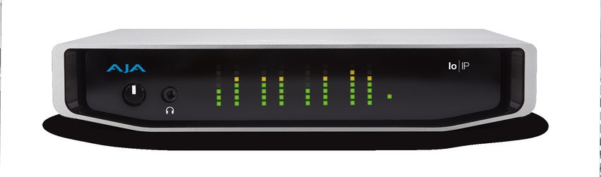
                                      Presets Screen  .  .  .  .  .  .  .  .  .  .  .  .  .  .  .  .  .  .  .  .  .  .  .  .  .  .  .  .  .  .  .  .  .  .  .  .  .  .  . 50
                                      Firmware Screen .  .  .  .  .  .  .  .  .  .  .  .  .  .  .  .  .  .  .  .  .  .  .  .  .  .  .  .  .  .  .  .  .  .  .  .  .  .51
                                      Info Screen .  .  .  .  .  .  .  .  .  .  .  .  .  .  .  .  .  .  .  .  .  .  .  .  .  .  .  .  .  .  .  .  .  .  .  .  .  .  .  .  .  .52
                                    Control Panel Operation in ST 2110 Mode . . . . . . . . . . . . . . . . . . . . . . . 52
                                      Overview .  .  .  .  .  .  .  .  .  .  .  .  .  .  .  .  .  .  .  .  .  .  .  .  .  .  .  .  .  .  .  .  .  .  .  .  .  .  .  .  .  .  .52
                                      General Operation .  .  .  .  .  .  .  .  .  .  .  .  .  .  .  .  .  .  .  .  .  .  .  .  .  .  .  .  .  .  .  .  .  .  .  .  .52
                                      IP Config Status Tab .  .  .  .  .  .  .  .  .  .  .  .  .  .  .  .  .  .  .  .  .  .  .  .  .  .  .  .  .  .  .  .  .  .  .  .53
                                      IP Config Capture Tab .  .  .  .  .  .  .  .  .  .  .  .  .  .  .  .  .  .  .  .  .  .  .  .  .  .  .  .  .  .  .  .  .  .  .54
                                      IP Config Playback Tab .  .  .  .  .  .  .  .  .  .  .  .  .  .  .  .  .  .  .  .  .  .  .  .  .  .  .  .  .  .  .  .  .  . 56
                                      IP Config Editor Window .  .  .  .  .  .  .  .  .  .  .  .  .  .  .  .  .  .  .  .  .  .  .  .  .  .  .  .  .  .  .  .  .57

                             Chapter 4 – Advanced ST 2110 Configuration .  .  .  .  .  .  .  .  .  .  .  .  .  59
                                    Configuration Summary .  .  .  .  .  .  .  .  .  .  .  .  .  .  .  .  .  .  .  .  .  .  .  .  .  .  .  .  .  .  .  .  .  .  .59
                                       Initial Io IP ST 2110 Installation and Network Configuration .  .  .  .  .  .  .  .  .  .  .59
                                       Transmit/Receive Example . . . . . . . . . . . . . . . . . . . . . . . . . . . . . . . 62
                                       AJA NMOS Controls  .  .  .  .  .  .  .  .  .  .  .  .  .  .  .  .  .  .  .  .  .  .  .  .  .  .  .  .  .  .  .  .  .  .  .  .62
                                    Transmit Redundancy with ST 2110 via ST 2022-7 .  .  .  .  .  .  .  .  .  .  .  .  .  .  .  .  .  .  .62
                                       For JSON Configuration (Transmit only) .  .  .  .  .  .  .  .  .  .  .  .  .  .  .  .  .  .  .  .  .  .  . 62
                                    Guidance for SMPTE ST 2110-23 .  .  .  .  .  .  .  .  .  .  .  .  .  .  .  .  .  .  .  .  .  .  .  .  .  .  .  .  .  .63
                                       For JSON Configuration  .  .  .  .  .  .  .  .  .  .  .  .  .  .  .  .  .  .  .  .  .  .  .  .  .  .  .  .  .  .  .  .  . 63
                                       For SDPs .  .  .  .  .  .  .  .  .  .  .  .  .  .  .  .  .  .  .  .  .  .  .  .  .  .  .  .  .  .  .  .  .  .  .  .  .  .  .  .  .  .  . 63

                             Appendix A – Specifications .  .  .  .  .  .  .  .  .  .  .  .  .  .  .  .  .  .  .  .  .  .  .  .  64
                                    Io IP Tech Specs .  .  .  .  .  .  .  .  .  .  .  .  .  .  .  .  .  .  .  .  .  .  .  .  .  .  .  .  .  .  .  .  .  .  .  .  .  .  .  . 64
                                    Audio Connection Pinouts .  .  .  .  .  .  .  .  .  .  .  .  .  .  .  .  .  .  .  .  .  .  .  .  .  .  .  .  .  .  .  .  . 67

                             Appendix B – Safety and Compliance .  .  .  .  .  .  .  .  .  .  .  .  .  .  .  .  .  .  68
                             Warranty and Liability Information  .  .  .  .  .  .  .  .  .  .  .  .  .  .  .  .  .  .  .  76
                                    Limited Warranty on Hardware .  .  .  .  .  .  .  .  .  .  .  .  .  .  .  .  .  .  .  .  .  .  .  .  .  .  .  .  .  . 76
                                    Limitation of Liability .  .  .  .  .  .  .  .  .  .  .  .  .  .  .  .  .  .  .  .  .  .  .  .  .  .  .  .  .  .  .  .  .  .  .  .  .76
                                    Governing Law and Language; Your Rights  .  .  .  .  .  .  .  .  .  .  .  .  .  .  .  .  .  .  .  .  .  . 76

                             Index .  .  .  .  .  .  .  .  .  .  .  .  .  .  .  .  .  .  .  .  .  .  .  .  .  .  .  .  .  .  .  .  .  .  .  .  .  .  . 78

Io IP Transport, Capture, Display v16.0r1                                                                4                                                                           www.aja.com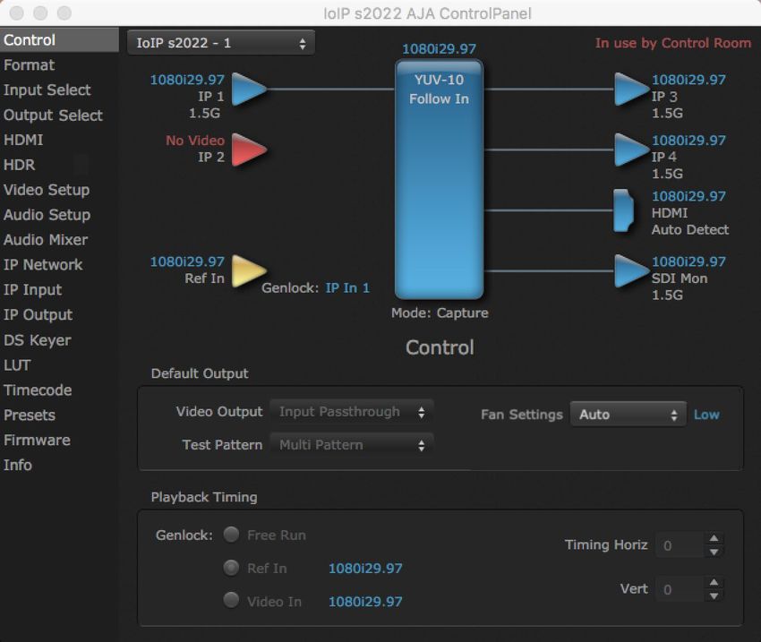
Chapter 1 – Introduction

Overview
                        Io IP is a powerful yet portable video and audio I/O device for professional IP
                        based workflows. As part of AJA’s industry-leading Io line of Thunderbolt capture
                        and playback devices, Io IP works seamlessly with a large number of popular
                        creative software applications, including out-of-the-box support for Adobe
                        Premiere® Pro, Apple FCP X, and Avid Media Composer®.
                        Designed as a flexible platform with support for SMPTE ST 2022-6 and ST 2110
                        uncompressed IP video/audio, Io IP brings the highest quality 4K/UltraHD, 2K, HD,
                        and SD video and audio over IP to computers running Mac or Windows Operating
                        Systems. Io IP can also support 4K/UltraHD p60 (2SI) capture or playback, via
                        SMPTE ST 2110-23..
                        Io IP is also supported through the very same SDK as the rest of the KONA family,
                        making it straight forward for developers to make the transition to Video over IP.

Io IP Features
                        Io IP is designed as a flexible platform for supporting various different IP
                        standards and types:
                         • SMPTE ST 2110 uncompressed HD video over IP, including Transmit support for
                            2022-7, thus providing for playout redundancy.
                         • SMPTE ST 2022-6 uncompressed HD video over IP including support for
                            2022‑7 Transmit and Receive.
                         • Io IP can also be configured to use all streams for input or output, thus
                            supporting up to 4K p60 uncompressed transport via ST 2110-23 (in this case
                            2022-7 support is not available)
                     NOTE: NDI is supported on Io IP in the same way as it is supported on KONA 4, courtesy
                           of running Newtek Connect.
                        Io IP supports different operating modes for different needs. By loading
                        a different version of firmware, you can tune your AJA hardware to the
                        requirements of the task at hand.

                        Video Formats
                        See "Appendix A Specifications" on page 64 for a listing of supported video
                        formats.

                        Physical Connection for IP Video
                          • 2 x 10 GigE Ethernet SFP+ Cages - SFP+ modules (not included).

Io IP Transport, Capture, Display v16.0r1                             5                                       www.aja.com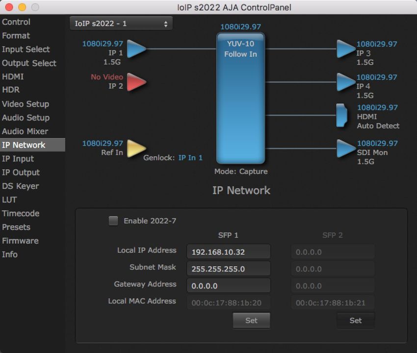
                        See "Appendix A Specifications" on page 64 for a list of SFPs tested by AJA.

                        Inputs and Outputs
                          • AJA Desktop Software package configured by default for ST 2022-6 operation
                            with two simultaneous uncompressed streams on the top SFP (one In, one
                            Out).
                          • For ST 2022-7 operation, a second SFP is used for redundant transport of the
                            other SFP's signals.
                          • When supporting 4K with Io IP via ST 2110-23, note that both SFPs are being
                            used in one direction, either input or output.
                          • Io IP HDMI output supports HDR signaling and monitoring for HDR10 and
                            HLG. HLG support is application dependent. Check with your software
                            manufacturer for compatibility.

                        Digital Audio Input
                          • 16-Channel embedded audio

                        Digital Audio Output
                          • 16-Channel embedded audio, 16- and 24-bit per channel, 48 kHz sample rate,
                            synchronous
                          • 8-Channel HDMI embedded audio, 48 kHz sample rate, synchronous

                        Signal Timing
                          • 1x BNC assignable to reference video or LTC input
                          • Relevant to SMPTE ST 2022-6/7 workflows only
                          • Not used for SMPTE ST 2110 workflows

                        Internal HD/SD Hardware Downstream Keyer
                        Io IP provides a powerful hardware keyer that can place graphic files with an
                        alpha channel over video in a selectable matte or the contents of the device’s
                        framebuffer from a software application (including AJA TV). Key a bug or text
                        over picture and avoid what might normally be a lengthy software render. Also,
                        working with these software applications, you can key video that has an alpha-
                        channel over video input or a matte. For example, you can load a QuickTime clip
                        that has an alpha-channel (a flying logo generated in the Animation codec) into
                        AJA TV and then place it over live video coming into the device and then passing
                        both on to a VTR for recording or broadcast.

                 NMOS
                        NMOS is a mechanism for providing discovery, registration and control in ST
                        2110 environments. A separate application, “AJA NMOS”, supports automatic
                        discovery of IP devices on the network, using an app (daemon) that operates in
                        the background with minimal user configuration. The first AJA device accessed by
                        the computer running the daemon can be discovered and subject to control by
                        an external NMOS network control application. NMOS uses the IP address of the
                        host machine for communications.
                        Generally, NMOS works as follows:
                         • When Io IP starts up, the NMOS app actively scans the network for an NMOS
                           registry using MDNS/DNS. If found, the NMOS registry is informed who the
                           Io IP device is, and its capabilities.
                         • If during startup the NMOS registry is not found, the NMOS app continues to
                           announce Io IP's presence via MDNS so that it can later be discovered, and
                           then after discovery, it can be manually registered in the network control
                           application.

Io IP Transport, Capture, Display v16.0r1                              6                                   www.aja.com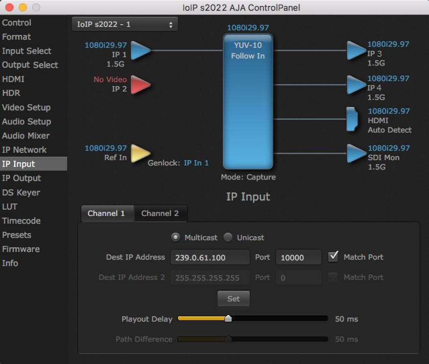
                        AJA NMOS is not installed by default ("complete") and should instead be selected
                        through the "custom" dialog if desired.
                        Once installed AJA NMOS can be set to launch upon reboot or power up. The
                        applications function is to make the Io IP discoverable and controllable by various
                        IP routing and control systems (e.g Imagine, LAWO, Sony). Discovery, registration
                        and network control are not part of SMPTE ST 2110 but are specified by JT-NM
                        NMOS or Network Media Open Specification. Two parts of this standard are IS-04
                        Discovery and Registration and IS-05 Connection Management.
                        When the tray icon is clicked (on the Mac or right click on Windows), the AJA
                        NMOS application offers a number of options:
                         • View Log - toggles opening or closing of the log window
                         • Stop/Start Service - allows the NMOS service to be stopped and restarted
                           without quitting the application
                         • Enable/Disable Debug Log - enables or disables the generation of debug
                           output to the AjaLogger and the log window
                         • Enable/Disable DNS Debug - enables or disables additional DNS debug
                           information (independent of Debug Log setting)
                         • Enable/Disable Verbose Debug - enables or disables additional debug
                           information if the Debug Log setting is enabled
                         • Select Interface - NMOS only uses one interface to access the registry. If there
                           is only one interface, then that is not a problem. If there is more than one, then
                           if auto is selected, it will automatically choose one based on whether it sees
                           any mDNS messages on one of the interfaces. Otherwise, the interface can be
                           selected.
                         • Set Registry IP - allows the registry ip address and port to be set manually.
                         • Quit - causes the NMOS application to exit

         AJA Software & Utilities
                        Io IP operates with AJA's Desktop software package, developed for powerful
                        integrated video/audio capture, editing, and production with a variety of 3rd-
                        party software. AJA software is distributed as a unified package which includes all
                        the software, firmware, plug-ins, and utility programs for the Io IP, as well as AJA’s
                        Io, KONA, and T-TAP products.
                        Two retail packages are available, one for Mac and one for Windows.

                 Mac and Windows Packages
                        These packages include:

                        Firmware
                        Firmware, otherwise referred to as a bit file or the Io IP's 'personality', refers to
                        very low level code that defines the capabilities of the hardware. It is important
                        to always update to the firmware recommended following install of new, or older
                        versions of software.

                        Drivers
                        AJA device drivers for the host system OS provide tightly integrated hardware/
                        software operation.

                        AJA Control Panel
                        The Control Panel provides:
                         • Source selection and control of your AJA hardware

Io IP Transport, Capture, Display v16.0r1                              7                                         www.aja.com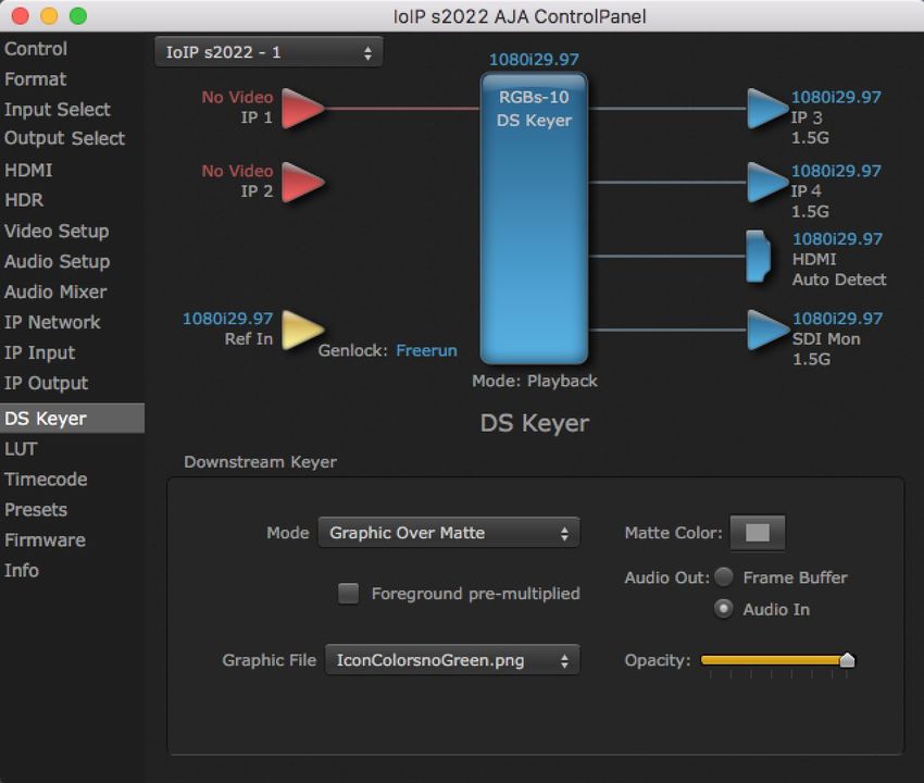
                          • A block diagram to show visually what routing and processing is being
                            performed

                        AJA Control Room
                        Control Room is a cross-platform software application for ingest, playback and
                        output with AJA products.

                        AJA System Test
                        AJA System Test provides accurate and detailed evaluations of drive and system
                        performance statistics, allowing you to measure the capabilities of your system
                        for recording and playing back various resolutions and codecs. The application
                        includes:
                         • System Disk Test
                         • AJA Device Test
                         • Disk + Device Test
                         • System Report
                        The application tests Read and Write, Capture and Playback speeds in both
                        Megabytes per second and Frames per second. The disk speed tests differ from
                        standard disk I/O performance applications in that they specifically test the
                        system under conditions typically encountered with video capture, playback, and
                        editing.
                     NOTE: Theoretically the best test (or simulation) is to fill your storage disk to 80% and
                           then test capture at the highest data rate you will use.

                        3rd-Party Plug-ins
                        Plug-ins for popular 3rd-party Professional Video Applications from Adobe, Avid,
                        Apple, Telestream, and others.

                        NMOS App
                        Available for automatic discovery of IP devices.

Network Requirements
                        For uncompressed workflows (SMPTE ST 2022-6 and SMPTE ST 2110) a 10GbE
                        switch is required.
                        For SMPTE ST 2110 specifically, a PTP clock source must also be deployed and the
                        switch must therefore also be PTP aware.
                        In all cases the switch used must be both managed (configurable) and IGMP
                        aware.
                        SFPs are not included with the purchase of Io IP. Recommended SFPs are listed in
                        "Specifications" on page 64.

System Requirements
                        AJA Video recommends that your system meet minimum hardware and software
                        requirements to achieve a satisfactory level of performance. Updates to system
                        requirements are subject to change.
                     NOTE: See Software Vendor system requirements for GPU recommendations and
                           additional hardware requirements and recommendations.

Io IP Transport, Capture, Display v16.0r1                                8                                       www.aja.com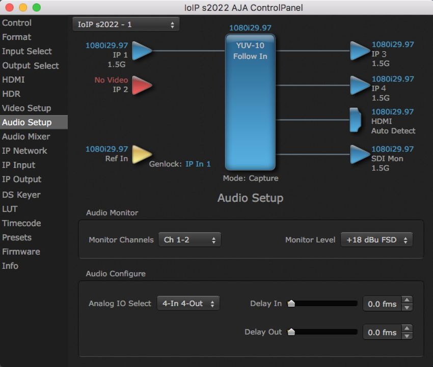
                        See the Io IP Release Notes, available on the AJA website and also installed with
                        the software package, for detailed system requirements including OS, CPU, RAM,
                        and GPU.
                        For IP installations specifically, AJA recommends:
                         • IP infrastructure with adequate bandwidth to sustain the capture and
                           playback of the material you expect to be working with across the number of
                           systems that are active at any given time
                         • For multi-seat installations, IP infrastructure that is comprised of fully
                           managed switches and is in turn supported by a team of qualified network
                           administrators
                         • For SMPTE ST 2022-7 implementations, two entirely independent network
                           infrastructures are required for true redundancy
                     NOTE: For large scale installations with shared storage, IP, or for very high performance
                           requirements, AJA recommends consultation with an experienced a system
                           integrator. A consultant will be able to assist with many important variables.

         Disk Storage Methods
                        To ensure performance and quality, the disk storage system used with
                        the workstation must be able to meet the demands of storing real-time
                        uncompressed media. At the very minimum, the disk storage system must be
                        able to provide and maintain a consistent transfer rate from the workstation to
                        disk (read/write). There are a variety of system configurations and peripherals that
                        can provide this level of performance.
                        For more on disk storage performance see "AJA System Test" on page 8.

Hardware Description
         Front Panel Controls and Indicators
                        Figure 1. Io IP Front Panel
                                                                     Audio Level          Power
                                                                      Meters (8)           LED

                          Monitor              Monitor Output
                        Gain Control         Connector 1/8 in. TRS

                        The Io IP front panel has the following controls and indicators:

                 Monitor Output and Gain Control
                        A 1/8 inch TRS connector is available for monitoring two channels of audio,
                        selectable in channel pairs using the Control Panel application. Typically used
                        with a pair of headphones.
                        The Monitor Gain knob on the left adjusts the monitor output level. Pushing in
                        the knob extends it (for adjustment) or recesses it (to prevent accidental changes).

Io IP Transport, Capture, Display v16.0r1                               9                                        www.aja.com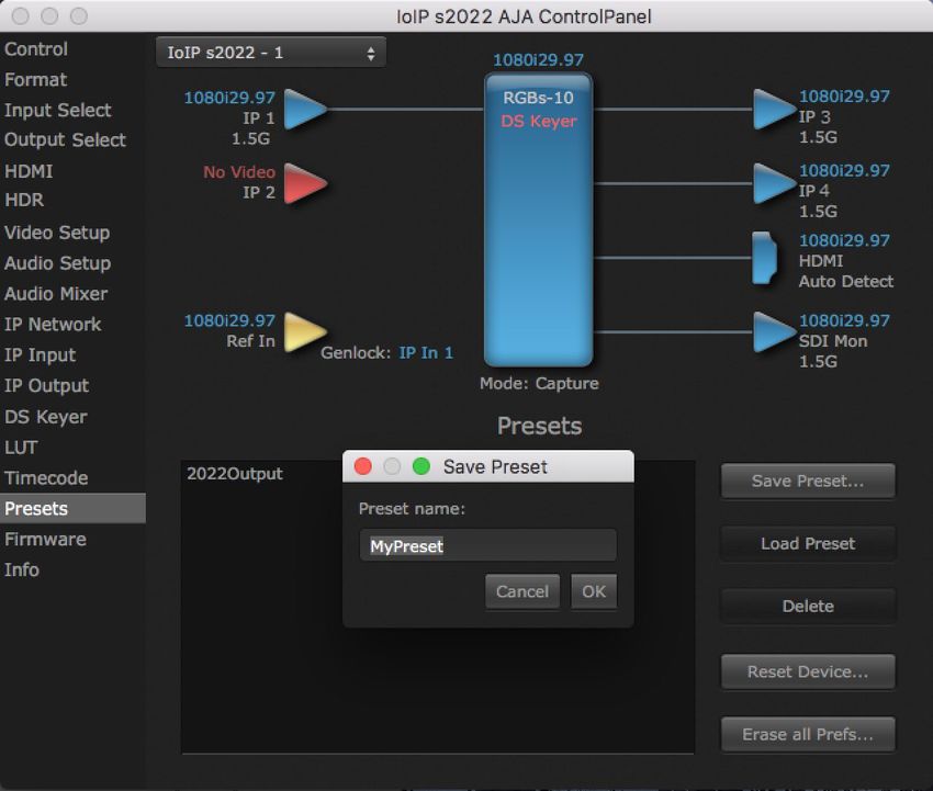
Audio Level Meters
The Audio Level Meters in the center of the front panel indicate:
• During Capture - The first 8 channels of the audio source selected (SDI, HDMI,
Analog)
• During Playback - The sum of whatever sources are being played out via
the AJA hardware; i.e. NLE timeline and mix of host system audio output (if
applicable)
The meter's LEDs are colored to indicate the amount below 0dBfs when averaged
over a one millisecond time interval:
dBfs LED Color and Location
-2 db Red LED 1 (top)
-12 db Yellow LED 2
-20 db Yellow LED 1
-30 db Green LED 4
-40 db Green LED 3
-50 db Green LED 2
-60 db Green LED 1 (bottom)
NOTE: These audio level meters are for guidance only. Third-party audio metering
should be employed when doing critical audio editing and mixing.
Power LED
The power LED lights up yellow when power is provided via the power supply.
Once a Thunderbolt 3 connection is made, and the host is in an active state, the
light turns green.
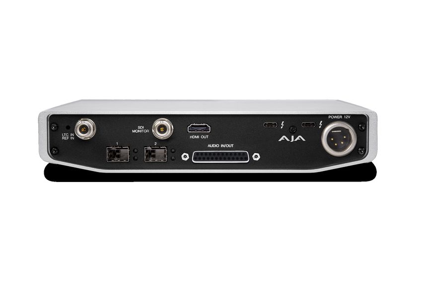
Rear Panel Connectors
Figure 2. Io IP Rear Panel
Reference or HD/SD-SDI HDMI Thunderbolt 3
LTC Input Monitor Out BNC Output Ports (2)
SFP Cage 1 SFP Cage 2 Balanced Audio In/Out 4-Pin XLR
DB-25F (8-Ch) DC Power Input
Thunderbolt 3
The Io IP provides the third-generation Thunderbolt 3 (USB-C) ports to support
increased bandwidth between host computer and I/O device. Two ports are
provided for daisy-chained network configurations.
Io IP Transport, Capture, Display v16.0r1 10 www.aja.com
                 SFP Cages and Modules
                        Two SFP+ cages are provided to connect two separate 10 Gigabit Ethernet Links.
                        Both links are bi-directional. Inputs and outputs for most uses will be set up over
                        the same link if bandwidth allows it.
                        For a list of SFP+ modules tested by AJA, see "Appendix A Specifications" on page
                        64.

                 Dedicated SDI HD/SD Output
                        One BNC connector is provided for full-time, real-time output of 2K/HD/SD video.
                        When running ST 2100 firmware, ANC data is included in the SDI monitor output.

                 HDMI Output
                        A full-size HDMI connector on the Io IP endplate provides HDMI 2.0 capability.
                        HDMI also supports multi-channel embedded audio (8 channels). HDCP is not
                        supported on the output. HDMI Output also supports HDR (HDR10 and HLG).

                 Reference Video
                        When in SMPTE 2022-6 mode, Io IP can lock to reference analog or tri-level input,
                        or the incoming SMPTE 2022-6 stream.
                        For analog reference, a single BNC on the Io IP endplate allows you to synchronize
                        Io IP outputs to your house analog or tri-level reference video signal (or black
                        burst). If you have a sync generator or central piece of video equipment to use
                        for synchronizing other video equipment in your studio, connect its output here.
                        When Io IP outputs video in SMPTE 2022-6 mode, it locks to this reference signal.
                        When connecting a reference video source, the locking signal should be the same
                        format as the Primary format selected in Io IP software. It is possible in some
                        circumstances to use an alternate format video signal if the basic frame rate is
                        compatible.
                        Io IP can also lock to an incoming SMPTE 2022-6 signal, or it can free run.

                 Balanced Analog Audio Input and Output
                        A 25-pin connector provides 8-channel balanced analog audio, 24-bit 48kHz
                        sample rate D/A and A/D, for use with an industry standard 8x XLR on DB‑25
                        breakout cable (cable not included). The eight analog audio channels can be
                        configured four different ways:
                         • Ch 1-8 Output
                         • Ch 1-4 Input and Ch 5-8 Output (default setting)
                         • Ch 1-4 Output and Ch 5-8 Input
                         • Ch 1-8 Input

                 12V Power Connector
                        A standard 4-pin XLR type connector is provided for either battery or line source
                        power using the supplied AC power adapter.

In This Manual
                        Chapter 1 - Introduces the product briefly, listing features and system
                        requirements.

Io IP Transport, Capture, Display v16.0r1                             11                                      www.aja.com
                        Chapter 2 - Provides complete instructions for installing and configuring the
                        product.
                        Chapter 3 - Discusses operational aspects and how to work with 3rd-party
                        software.
                        Appendix A - Presents a list of technical specifications for the product.
                        Appendix B - Provides important Safety and Compliance information.

Io IP Transport, Capture, Display v16.0r1                             12                                www.aja.com
Chapter 2 – Installation

Installation Overview
                        1. If not previously installed on your Thunderbolt equipped computer, ensure
                           that appropriate third party application software is installed as detailed in
                           its user documentation.
                        2. Download and install the latest Io IP software from:
                            https://www.aja.com/en/support/downloads
                        3. Connect your Io IP to your computer using an appropriate Thunderbolt 3
                           cable (and adapter if required). Information about Thunderbolt including
                           cable recommendations is available here:
                            https://www.aja.com/solutions/thunderbolt
                        4. Insert compatible SFP module(s) into the SFP cage(s) and connect to your
                           media network.
                        5. Connect the video and audio inputs and outputs to your Io IP .
                        6. Power up the unit (AC supply or battery). The Io IP will startup automatically.
                     IMPORTANT: You should wait at least two minutes after Io IP powers up before you open
                           AJA Control Panel.
                        7. When you run AJA Control Panel, the Io IP is auto-discovered as long as it is
                           properly cabled and powered up.
                        8. You will now be able to configure your Io IP for operation on your network.

Unpacking
         Shipping Box Contents
                        As you unpack your shipment, carefully examine the contents. Ensure you
                        received everything and that nothing was damaged during shipping. If you find
                        any damage, immediately notify the shipping service and supply them with a
                        complete description of the damage. AJA will repair or replace damaged items.
                        If you find shipping damage, contact your AJA dealer or distributor for details on
                        how to have your AJA device repaired or replaced.
                     NOTE: Save packing materials and the shipping box. If you ever require service or move
                           your system use the packaging materials and box for safe shipment.

Installing Io IP Software
                     NOTE: If your computer has previously had another video capture or multimedia device
                           installed, ensure you uninstall any related software before installing Io IP. This will
                           prevent any hardware or software conflicts.

Io IP Transport, Capture, Display v16.0r1                                13                                          www.aja.com
                        Before installing the AJA Desktop Software package, ensure that your capture/
                        editing application is installed as detailed in its user documentation. You cannot
                        use the AJA Desktop Software package with a third-party application until the
                        application has been installed and run at least once on your workstation. Next,
                        install the AJA Desktop Software package. If at a later date you add any Io IP
                        supported applications that require drivers, you must run the AJA install program
                        again to install them.
                     NOTE: Always uninstall the previous version of the AJA Desktop Software package
                           before updating your Io IP.

         NMOS Installation
                        Io IP supports NMOS (Networked Media Open Specifications), using a stand-
                        alone AJA NMOS application. The AJA Installer does not install the AJA NMOS
                        application by default. You must select NMOS using the "Custom" option during
                        installation, and to enable this feature you will also need to manually launch this
                        application and be connected to a network that has a running NMOS control
                        application.
                     NOTE: If you do not install AJA NMOS on your computer, NMOS control systems will not
                           be able to register or control Io IP.

         macOS Installations
                        macOS High Sierra (10.13), macOS Mojave (10.14), macOS Catalina (10.15) and
                        macOS Big Sur (11.x) all have security requirements that may present dialogs
                        during installation. Please refer to the Release Notes for guidance

         Io IP Firmware Installation
                     IMPORTANT: The firmware installed in your Io IP should match the version of the AJA
                           software package. If a mis-match is present, the Io IP may not work and a "Not
                           Valid, device needs firmware update" message will be displayed. Always update
                           the firmware of your Io IP when you install an AJA software package.

                 Types of Io IP Firmware
                        AJA Desktop Software can provide the Io IP with two different personalities, or
                        modes of operation.
                         • SMPTE ST 2022-6 operation (s2022) uses the IoIP s2022 firmware bitfile
                         • SMPTE ST 2110 operation (s2110) uses the IoIP s2110 firmware bitfile
                        Switching between these different Io IP operating modes requires loading the
                        appropriate firmware bitfile as listed above.
                        By default, newly purchased Io IP hardware will come pre loaded with ST 2022
                        firmware. Loading the s2110 bitfile will provide that functionality.

Cabling the System
                        See "Rear Panel Connectors" on page 10.

Io IP Transport, Capture, Display v16.0r1                             14                                      www.aja.com
         Io IP Cable Connections
                        For 2022-6 and 2022-7 operation, 10GbE infrastructure can be connected
                        with either a short (3 feet) Direct Attached cable, or optical fiber cable with
                        appropriate SFPs.
                        Figure 3. IP Configuration Example for 2022-6 Workflow
                                                                     10 Gb Ethernet Switch                                        HDMI

                                                                                                                                                HDMI Monitor
                                                                                                       HDMI
                                            Workstation A                                                     Workstation B
                                             with Io IP                                                        with Io IP

                                                               10 Gb                         10 Gb
                                                              Ethernet                                                                       Receive live video
                                                                                            Ethernet                                        from Workstation A,
                                                                                                                                            downstream key and
                                                                                                                                            live re-transmit to a
                                                                                                                                            different IP address.
                                                 Video Switcher or other
                                                   facility destination                          Workstation C
                                                                                                 with KONA IP
                              Broadcast                                           10 Gb
                               Monitor                                           Ethernet

                                                                                                                                Capture live video
                                                                                                                               from Workstation A
                                                                                                 and KONA 4                    with KONA IP, edit,
                                          SDI                SDI
                                                                                                                                 and subsequent
                                                                                                                              SDI playout to facility
                                                                               SDI                                            through KONA 4 card.

                                                KUMO 3232

                        Figure 4. IP Configuration Example for 2022-7 Workflow
                                                                   10 Gb Ethernet Switch

                                                                                                       Workstation B
                                                                                                       with KONA IP           Redundant video transmit
                                           Workstation A      10 Gb               10 Gb                                        to different network legs
                                            with Io IP       Ethernet            Ethernet                                           for redundancy.

                                                                        Redundant
                                                                   10 Gb Ethernet Switch

                 SFP Module Connections
                        For SMPTE 2022-6 / SMPTE 2022-7 operation (s2022), modules inserted into the
                        two SFP+ cages can be used to connect two separate 10 Gigabit Ethernet Links.
                        With AJA Desktop Drivers, the SFP 1 and 2 modules are configured using AJA
                        Control Panel software, using the Input, Output, and Network Settings tabs. In
                        most cases, only SFP 1 will be used, providing up to two total streams of SD or
                        HD video, each with 16 audio channels and metadata, for simultaneous input or
                        output, i.e. when using SMPTE 2022-6. Both links are bi-directional (one In, one
                        Out). When using SMPTE ST 2022-7, the Lower SFP carries a duplicate of the Upper
                        SFP data.
                        For a list of SFP+ modules tested by AJA, see "Appendix A Specifications" on page
                        64.

Io IP Transport, Capture, Display v16.0r1                                                   15                                                                www.aja.com
Unicast and Multicast Support
                        Io IP supports both unicast and multicast operation. Unicast operation is point to
                        point, from one sender to one receiver. Multicast operation is from one sender to
                        possibly multiple receivers. In both cases, the sender transmits information to a
                        location (IP address) on the network, and receivers access that information over
                        the network using that location IP address. Compatible IP addresses are required
                        for each type of operation. These network settings filter the IP addresses so the
                        information is sent successfully to the desired receiver(s).
                     IMPORTANT: Proper network configuration settings vary, depending on your particular
                           network environment. Because the process can be complicated, you should
                           always consult with your facility's IP or Networking Engineering department
                           before configuring Io IP network settings.
                        Listed below are example sets of compatible IP addresses that could be used in
                        an isolated network to test Io IP network operation.

                        Table 1. Example Compatible Unicast IP Addresses
                          Control Panel Screen     Parameter                Io IP 1 (send)           Io IP 2 (receiver)
                          IP Network               Local IP Address         192.168.10.31            192.168.10.32
                                                   Subnet Mask              255.255.255.0            255.255.255.0
                          IP Input                 Destination IP Address          ---               192.168.10.41
                                                   Destination Port                ---               2000
                          IP Output                Destination IP Address   192.168.10.41                   ---
                                                   Destination Port         2000                            ---

                        Table 2. Example Compatible Multicast IP Addresses
    Control Panel Screen        Parameter                Io IP 1 (send)       Io IP 2 (receiver 1)          Io IP 3 (receiver 2)
    IP Network                  Local IP Address         192.168.10.31        192.168.10.32                 192.168.10.33
                                Subnet Mask              255.255.255.0        255.255.255.0                 255.255.255.0
    IP Input                    Destination IP Address           ---          239.0.61.100                  239.0.61.100
                                Destination Port                 ---          10000                         10000
    IP Output                   Destination IP Address 239.0.61.100                   ---                           ---
                                Destination Port         10000                        ---                           ---

Io IP Transport, Capture, Display v16.0r1                              16                                                  www.aja.com
Chapter 3 – Io IP Operation

Using Io IP with Professional Video /Audio Software
                        After you install the AJA software package on your computer, you’re ready to
                        begin capturing and playing back video and audio using your choice of third-
                        party software. You can go here for AJA software and documentation:
                            https://www.aja.com/en/support/downloads
                        For further support information and downloads for third-party software, go to:
                            https://www.aja.com/compatibility/io
                        Frequently Asked Question documents for various AJA products are available at:
                            https://www.aja.com/products/kona-ip#support

         Capture Formats
                        When capturing, you can record data in the following file formats:
                         • DPX
                         • TGA
                         • BMP
                         • QuickTime
                         • MXF
                     NOTE: Support by Io IP of QuickTime for Windows has been discontinued. Instead, AJA
                           supports ProRes family capture and playback for macOS and Windows via AJA
                           Control Room.
                     NOTE: Other file types can be captured using third-party capture applications such as
                           Sienna, Softron, Tools on Air, Drastic Technologies, or Quadrus.

AJA Control Panel Overview
                        The AJA Control Panel is a software application that provides a simple visual
                        showing how the Io IP hardware is currently configured and allows you to make
                        changes. You can change signal input and output parameters and define the
                        video processing that will be performed.
                        The AJA software installer automatically installs the Control Panel application on
                        your computer.

Io IP Transport, Capture, Display v16.0r1                             17                                     www.aja.com
         AJA Control Panel Operating Modes
                        AJA Control Panel has two fundamental operating modes.
                        Playback Mode - Used for playing back video files from the computer, usually
                           with a non-linear editing application (NLE) or AJA Control Room, through the
                           Io IP’s video/audio outputs for viewing and/or external recording.
                        Capture Mode - Used for capturing video/audio signals that are coming into the
                          Io IP from an external source to create video files on the computer using AJA
                          Control Room or an NLE, or just for display on the Io IP outputs. This mode is
                          also used for stand-alone video display or conversion when Control Panel is
                          being used without an external controlling application.

         AJA Control Panel User Interface
                        The AJA Control Panel user interface includes a visual block diagram of the unit’s
                        current configuration. The current status, input and output settings, and many
                        other details are depicted in the color-coded block diagram. Below this block
                        diagram are various controls for changing operating parameters, which will vary
                        depending on which function screen has been selected.
                        The left side of the AJA Control Panel provides a navigation list of available
                        function screens. Clicking on a link (or alternatively, a related element in the block
                        diagram) displays a function screen corresponding to that topic.
                     NOTE: Although Io IP is sending and receiving video over IP, once that data is decoded
                           to memory it is governed by the same video menus used for SDI and HDMI based
                           AJA I/O solutions.

                        Figure 5. AJA Control Panel, Block Diagram and Controls
                                                                                                                 Framebuffer
        Currently                                                                                                   Format
        Selected                                                                                                   (Primary)
        Function
         Screen
        AJA Device
         Selection
                                                                                                                   Outputs
          Inputs

       Parameter
        Controls

Io IP Transport, Capture, Display v16.0r1                             18                                               www.aja.com
                 Block Diagram Area
                        The top block diagram area of the Control Panel screen is a visual representation
                        of the processing, if any, that’s currently occurring, including inputs/outputs,
                        reference source, and system status. Lines between inputs, the framebuffer, and
                        outputs, show a video path. Where there are no lines, there is no connection; this
                        can be because an input or output isn’t selected in the Input Select menu. The
                        lines will also show whether the outputs are video or video + key.
                        You can click any of the function screen selection links in the left column to view
                        its current settings or click on an icon to call up its related settings screen. You can
                        also right-click or Control-click to see context-sensitive information and choices.
                        Figure 6. Context Sensitive Menu

                 Color Meanings
                        All items in the AJA Control Panel block diagram are color-coded to show what is
                        happening in real time. This applies to both icons and text. These colors indicate:
                        Blue - Video is same format as the Primary Format (framebuffer)
                        Yellow - Reference video (black burst or other reference source)
                        Red - The selected operation cannot be performed

                 Input/Output Icons
                        The input and output icons are triangles that together with their color show all
                        the input and outputs and their status (selected, not selected, input present or
                        not, format, etc.). A complete video path is shown when inputs and outputs are
                        connected with lines going to/from the framebuffer.
                        Figure 7. Input/Output Icons

                 Framebuffer
                        The framebuffer is the “engine” where your third-party applications interface with
                        the AJA device. The framebuffer has a format (called the “Primary Format”) and
                        color space that it follows, as defined in the linked menu screens or via external
                        application software.

                 Device Format
                        The Device Format is the media format written to disk and used in your project.
                        This is the format that the framebuffer will use and is shown in the Control Panel
                        using the color blue. It is the format that the third-party application software will
                        either receive from the AJA hardware, or is sending to the hardware. All icons in
                        blue are the same as the Device Format used by the framebuffer. Also any text
                        descriptions in the block diagram that appear in blue indicate that something is
                        in the Device Format. For example:

Io IP Transport, Capture, Display v16.0r1                              19                                          www.aja.com
                          • If the input and output icons are blue, you know that the same format is used
                            throughout the video path. No format conversion is being performed.
                          • If the input or output icon colors differ (blue input and green output icons for
                            example), you know that a format conversion is being performed.

         Controlling Application
                        Figure 8. Control Panel In Use Message (in red)

                        In the top right corner, the Control Panel displays the name of the application
                        controlling the unit. In some cases, applications may not always properly “let go”
                        of the I/O interface as another takes over—you’ll be able to tell by looking at the
                        Control Panel.

         Presets
                        Setups can be named and saved as a snapshot (Preset) for recall at any time. You
                        can save various AJA device Control Panel configurations associated with your
                        frequent tasks. You don’t have to spend time resetting interface configurations,
                        just load the previously saved Preset for each task. See "Saving, Loading and
                        Deleting Presets" on page 50 for more information.
                        If you work on multiple systems and want to carry your saved setups to another
                        location, you can copy your saved Preset files on to movable storage and load
                        them into any computer running the AJA Control Panel application.

                        Mac OS Preset Files Storage Location
                          • From the Finder, hold down the Option key (to display the Library directory)
                            and click on Go/Library/Application Support/AJA//Presets/

                        Windows Preset Files Storage Location
                          • c:\Users\\AppData\Local\AJA\Control Panel\
                            Presets\
                     NOTE: When you visually browse to the above location, depending on Windows OS
                           setting you may not be able to visually see the folder referred to in the path.
                           Instead, you have to fill out the rest of the Windows path manually (i.e. type the
                           rest of the address in the navigation bar when you hit the "end" of the browsing
                           path).

         Default Preferences
                        When an AJA device starts up, a preference can determine what settings it will
                        have it when it begins to operate. The AJA Control Panel offers two default
                        preference settings:
                         • Local Preference - A preference stored from the last AJA device's Control Panel
                           settings to be used on next startup of AJA Control Panel. This occurs on next
                           restoration of the default state (triggered by start up of host CPU, startup of
                           the AJA device, or when a third-party application releases the AJA device).
                         • Global Preference - A preference saved for use as a global default start state
                           for an AJA device that can be shared by multiple users, applied on first startup,
                           or by pressing the Control Panel Reset Device... button.

Io IP Transport, Capture, Display v16.0r1                              20                                       www.aja.com
                 Local Preference
                        The Local Preference file (com.aja.devicesettings) exists to immediately and
                        automatically store all parameter changes made by a user on a particular AJA
                        device. When any control is changed in the Control Panel, that change is recorded
                        in the Local Preference file stored in a unique location on that computer that is
                        dedicated to that particular device, serial number, and logged-in user. Then, when
                        AJA Control Panel is restarted for any reason, the AJA device being controlled
                        restores the settings being used when Control Panel was last closed.
                        The Local Preference file can be accessed at the following locations.
                        On Mac:
                           • From the Finder, hold down the Option key (to display the Library directory)
                             and click on Go/Library/Preferences/com.aja.devicesettings.
                        On Windows:
                           • C:\Users\\AppData\Local\aja\com.aja.devicesettings
                     NOTE: Clicking on the AJA Control Panel "Erase All Prefs" button deletes the existing
                           Local Preference file from this location. This file will be recreated as soon as any
                           Control Panel setting is changed.
                     NOTE: Clicking on the AJA Control Panel "Reset Device..." button will delete the existing
                           Local Preference file. If a Global Preference file is found, these settings are
                           reloaded. If a Global Preference file is not found, “factory defaults” are loaded and
                           the device is set to that state

                 Global Preference
                        An administrator can establish a house standard for an AJA device by copying
                        a preference file to a shared computer location. Once placed at that location, it
                        becomes a Global Preference file where it will establish a standard default startup
                        state for all users of that AJA device using that computer system. These settings
                        preempt the initial AJA factory default settings, and are applied when an AJA
                        device is first powered up, or when the Control Panel Reset Device button is
                        pressed.
                        To establish a Global Preference, the administrator first configures the AJA device
                        (which automatically creates a "com.aja.devicesettings" Local Preference file in
                        the location identified above) and then copy or move or that file to the correct
                        computer locations (manually or by pushing it out across the network) on all the
                        computers that use the AJA device.
                     NOTE: If the user makes changes to an AJA Device's Control Panel settings, those
                           changes are saved to the Local Preference file, which will take priority over the
                           Global Preference file.
                        The shared computer locations for a Global Preference file are:
                        On Mac:
                         • From the Finder, click on Go/Computer//Users/Shared/AJA/
                           and copy or move the "com.aja.devicesettings file" described above to this
                           location.
                     NOTE: The "AJA" folder needs to be created manually at this location before moving the
                           preference file into it.
                        On Windows there are three possible shared locations depending on your system:
                         • C:\Users\Public\Aja\
                         • C:\Users\All Users\Aja\
                         • C:\ProgramData\Aja
                            Copy or move the "com.aja.devicesettings file" described above to one of
                            these locations.

Io IP Transport, Capture, Display v16.0r1                                21                                        www.aja.com
                     NOTE: The AJA Control Panel Info screen displays the path to the Global Preference file
                           on that computer.
                     NOTE: Clicking on the AJA Control Panel Erase All Prefs button does NOT delete an
                           existing Global Preference file from this location.

         Io IP Audio Monitoring
                        Io IP hardware can be used as your single audio monitoring solution whether
                        you are auditioning music in a web browser, playing a movie file on the desktop,
                        creating music, or playing a YouTube clip. As long as the output of your work
                        or application is normally output via the host system audio, your AJA hardware
                        can route this audio for monitoring. This cuts down on unnecessary cabling, and
                        means you can take advantage of a consistent audio monitoring environment
                        whatever you are currently doing with your host system.
                     NOTE: On first use, you will need to tell your operating system to use AJA hardware as
                           the default Input and Output hardware.
                        Io IP lets you listen to Host System audio concurrently with your NLE audio. This is
                        useful if you need to audition music tracks against playback of your NLE timeline,
                        or if you need to Skype with a remote producer during an edit session, or for a
                        myriad of other reasons.
                        You can also listen to Io IP Input concurrently with your NLE (with the exception of
                        Avid Media Composer). This is useful if you need to listen out for the readiness of
                        talent, or the presence of some other feed, whilst you continue to work.
                        Io IP audio monitoring is routed and mixed using the Control Panel application's
                        Audio Mixer screen. You can select sources to be monitored, and can adjust
                        their levels. If you are using the 1/4 inch monitor output connector, an additional
                        overall mix gain control is conveniently available on the Io IP's front panel.
                        The mixed audio monitor signal is routed to:
                         • Front Panel Monitor Output (headphone jack)
                         • SDI Embedded Audio Out
                         • HDMI Embedded Audio Out
                         • Analog Audio Out (via DB25 cable)
                     IMPORTANT: Even though you can hear changes in the signals and levels adjusted with
                           the Audio Mixer screen, these changes are NOT recorded to disk during NLE
                           Capture or Audio Punch In / Voice Over to Timeline. The Audio Mixer screen is
                           dedicated for monitoring only, not program mixing.

Io IP Transport, Capture, Display v16.0r1                              22                                      www.aja.com
                        Figure 9. Io IP Audio Monitoring Routing Diagram
                                               Audio Capture
                                             Punch In/Voice Over
                                                Record to File

                          Non Linear
                         Video Editor               NLE
                                                 Application                    NOTE: NLE audio
                                                                               output is disabled
                                                                               in Capture mode.

                                Control Panel                                               Control Panel                      AJA Hardware
                                                                                                                              Audio Monitoring
                                Input Select                                                 Audio Mixer
                                  Screen                                         NLE           Screen
                                                                                Audio                                         SFP Out with SDI
                                                                                                                              Embedded Audio
                                                                   AJA Hardware Audio
                                                                                                                              HDMI Embedded
                          AJA Hardware                                                                       Mixer             Audio Output
                           Audio Input                                                                      Controls
                                                                                                                                   Analog Audio
                           SFP In with SDI                                                                                           Output
                          Embedded Audio
                                                                                                                                   Front Panel
                          Analog Audio                                         Host                                               Monitor Output
                             Input                                           Computer
                                                                               Audio                                   Gain
                                                                                                                       Knob

                          Host Computer Audio Input
                           Audio File
                           Playback
                                                  Mac or PC
                            YouTube               Computer
                             Other                  Audio
                            Sources

                        To control which AJA hardware audio is used during recording, you use the
                        Control Panel application's Input Select Screen, Audio Input Select drop down to
                        select from:
                         • SDI embedded
                         • Analog (via DB25 cable)
                        Any level adjustments to Capture or Audio Punch In / Voice Over to Timeline
                        recording operations will either need to be made upstream of the AJA input, or
                        else via adjustments within the main NLE application (e.g. via a pass through mix
                        tool).

         Control Panel Function Screens
                        Table 3. Io IP Function Screens
                          Screen                   Functions
                          Control                  Configure some basic Io IP operation options and output timing.
                          Format                   Select the framebuffer Device format.
                          Input Select             View and edit input selections and audio mapping.
                          Output Select            Select output format.
                          HDMI                     Configure the HDMI Output
                          HDR                      Configure High Dynamic Range settings for HDMI output
                          Video Setup              Configure Video such as composite black level, progressive format and
                                                   ancillary data (Closed Caption) option.
                          Audio Setup              Configures Audio options such as analog audio monitor level.
                          Audio Mixer              Select and mix audio sources for playback and capture.
                          IP Config                (ST 2110 only) Configure network parameters.
                          IP Network               (ST 2022 only) Configure network parameters for the location of each Io IP
                                                   physical SFP cage.

Io IP Transport, Capture, Display v16.0r1                                                  23                                                      www.aja.com
                          Screen            Functions
                          IP Input          (ST 2022 only) Configure parameters for receiving inputs from the media
                                            network.
                          IP Output         (ST 2022 only) Configure parameters for sending outputs to the media
                                            network.
                          DS Keyer          Setup and control the insertion of keyed video from the frame buffer or
                                            graphics files with alpha channel.
                          LUT               Load a lookup table (LUT) file to adjust the calibration of color for any
                                            source.
                          Timecode          Monitors SMPTE 12M-2 timecode and configure timecode window burn
                                            output.
                          Presets           Add or delete saved preset configurations (handy for quick and easy recall
                                            of different Io IP settings for varied workflows).
                          Firmware          Install firmware from your currently installed AJA software package.
                          Info              Display status information and the firmware version number. This
                                            information is generally intended for troubleshooting/support.

About Io IP Modal Operation
                        Io IP supports modal operation. Functionality depends on what firmware has
                        been installed on that device. Different Control Panel screens are displayed,
                        depending on the operating mode.
                        For Io IP you can choose to install:
                         • Io IP s2022—For use only with ST 2022-6 full bandwidth video, and supports
                           use of two SFPs for up to four uncompressed HD streams.
                         • Io IP ST 2110—For use only with full bandwidth video, supports use of two
                           SFPs for up to two input and two output uncompressed HD streams, and
                           permits transport of individual video or audio streams, or a set of multiple
                           video and audio streams.
                        Most ST 2022 Mode functionality also resides in ST 2110 Mode, with some
                        exceptions.

Io IP Transport, Capture, Display v16.0r1                              24                                               www.aja.com
Control Panel Operation in ST 2022-6 Mode
         Control Screen

                        The Io IP can be controlled by various software applications running on a host
                        computer. The Control screen is where you select how the Io IP directs video and
                        is used by application software. This screen also provides control for configuring
                        output timing with regard to external reference video and horizontal/vertical
                        delay. The top of the Control Screen shows the currently selected AJA device if
                        more than one is available in your system.

                 Default Output
                        This is where you select what the Io IP will output as a default when no
                        application has control of the board, such as when the Mac Finder or Windows
                        Navigation Pane is active. Since Io IP can be controlled by software applications
                        as well as its own control panel, the output can change dynamically. When you
                        select many video applications, they will take control of the Io IP inputs and
                        outputs. However, when an application that doesn’t take control is active, these
                        settings determine what Io IP will output.

                        Input Passthrough
                        This selection directs Io IP to route video from its selected input through the
                        device for processing and output.

                        Test Pattern
                        This selection directs the Io IP to output a choice of preset pattern when no other
                        application is using the Io IP. You can choose from:
                         • Black, Color Bars (75% or 100%), Ramp, Multiburst, Line Sweep, Multi Pattern,
                           or Flat Field, Check Field, White, Border, Linear Ramp, Slant Ramp, Zone Plate,
                           and Color Quadrant

Io IP Transport, Capture, Display v16.0r1                            25                                       www.aja.com
                        In addition to the preset test pattern choices, a “Load File...” selection at the
                        bottom of the menu allows you to load any standard RGB graphics file (.tif,.psd,
                        etc.) into the frame buffer for display.
                        While in Test Pattern mode, you can select RGB or YUV output via a pulldown
                        menu.
                     NOTE: The graphic file will not be scaled to fit. If it’s smaller than the current frame
                           buffer format, Io IP will center it in the frame. If it’s larger than the current frame
                           buffer format, it will be cropped on the right and bottom. Also some graphics
                           formats and bit depths may not be supported. Once a graphic file is loaded into
                           the frame buffer it will be retained until it is overwritten by another graphic or test
                           pattern, or when power is turned off. Graphic file names are only “remembered”
                           in the menu until the AJA Control Panel application closed.

                        Hold Last App
                        This selection directs Io IP to hold and output the last frame of video from the last
                        application to control Io IP. This can be helpful when operating in an environment
                        where you’re switching back and forth between multiple application windows.

                        Fan Settings
                        Io IP offers a fan speed control. The High setting forces maximum fan cooling,
                        with some increased noise, but this setting could be appropriate if the unit is
                        located in, for example, a machine room rather than an editing suite.
                         • Auto - Fan speed controlled by temperature, increasing or decreasing
                            automatically.
                         • High - Fan always operates at its highest speed.

                 Playback Timing
                        Use these controls to set Genlock and Timing adjustment.

                        Genlock
                        Selects how Io IP will synchronize program video:
                         • Freerun - In this mode, Io IP generates sync without an external reference
                           source
                         • Ref In - Directs Io IP to use the Ref Video source for sync (usually an analog
                           black burst video signal)
                         • Video In - Directs Io IP to use whichever video input source has been selected
                           in the Inputs Screen for sync

                        Timing (Horiz and Vert):
                        These two pull-downs allow output timing adjustment with reference to the Ref
                        Video source selected:
                         • Horizontal selects a number of pixels (clocks) to offset
                         • Vertical specifies a number of lines to offset

Io IP Transport, Capture, Display v16.0r1                                26                                          www.aja.com
         Format Screen

                        The Format Screen shows the video format currently in use by the Io IP
                        framebuffer (called the Primary Format) and allows you to change it. All
                        throughout the Control Panel, choices are always presented based on what Io IP
                        can do with the signals available and the inputs/outputs selected.

                 AJA Device Format
                        Video Format
                        This pull-down menu shows the currently selected Device format. If you select
                        an alternate value using the pull-down, it will change the format used by Io IP’s
                        framebuffer.
                        When a change is made via the Video Format pull-down or by clicking an icon
                        and selecting a new format via a contextual menu, the block diagram will change
                        to reflect the new format.

                        Pixel Format
                        Use this pulldown menu to choose: YUV-10, YUV-8, RGB-10, or ARGB-8 or RGB-12.

                        RGB Range
                        The RGB Range pulldown menu allows you to select either Auto, Full-range (0-
                        1023) or SMPTE range (typically 64-940) for RGB color output.

                        Follow Input
                        Enabling the Follow Input checkbox allows the Control Panel Buffer to auto-
                        switch to whatever is the detected input format. This feature works only if the
                        controlling application supports input-based capture—AJA Control Room for
                        example.

Io IP Transport, Capture, Display v16.0r1                            27                                     www.aja.com
         Input Select Screen

                        On the Input Select Screen you can view the currently selected video and audio
                        input sources and map audio sources to the channels supported by your editing
                        application.

                 Video Input
                        Source
                        The pulldown menu allows you to change the currently selected video input.
                        Select from IP 1 or IP 2.

                        LTC/Ref
                        Use the LTC/Ref menu pulldown to identify the type of signal being received by
                        the LTC/Ref BNC:
                         • Reference - BNC is used as a video reference input
                         • LTC- BNC is used for linear time code (LTC) input

                        SDI Color Sp
                        Sets the color space. Select from Auto, YUV, or RGB.

                        SDI RGB Rng
                        Sets the RGB range. Select from Auto, SMPTE, or Full.

Io IP Transport, Capture, Display v16.0r1                            28                                  www.aja.com
                 Audio Input
                        Select the audio input. Choose from:
                         • Analog - Analog input (four or eight channels, depending on configuration).
                         • IP1 Ch 1-16 - IP1 embedded SDI or HDMI incoming audio (up to 16 mono
                           channels)
                         • IP2 Ch 1-16 - IP 2 embedded SDI or HDMI incoming audio (up to 16 mono
                           channels)

                        Ch Map
                        If only two channels were selected in the third-party application you are using,
                        you can select which two channels will be mapped to that application. Different
                        Audio Input selections can have different channel mapping capabilities. Select
                        from:
                          • 1-2 to 1-2
                          • 3-4 to 1-2
                          • 5-6 to 1-2
                          • 7-8 to 1-2
                          • 9-10 to 1-2
                          • 11-12 to 1-2
                          • 13-14 to 1-2
                          • 15-16 to 1-2
                     NOTE: This setting does not affect the embedded audio being sent to the Io IP's BNC or
                           HDMI output connectors.

         Output Select Screen

                        The IP Output Screen shows the current settings for both of the IP outputs. The
                        outputs can be configured independently.

Io IP Transport, Capture, Display v16.0r1                             29                                      www.aja.com
                 Output Options
                        Select
                          • Auto - Automatically selects the output format, based on the input or selected
                            format.
                          • Primary - Selects the framebuffer format for output.
                          • Video+Key - When selected, this indicates that the SDI 3 video is set to the
                            same format as the framebuffer. SDI 4 is set to a video key signal associated
                            with SDI 3 (the shape to be cut out from the video - this will appear as a black
                            and white image/matte). Using the second Io IP output as an Alpha Channel
                            key, with the video output, may be useful for feeding production switchers,
                            DVEs or other professional video equipment.

                        Color Space
                        Sets the color space. Select from Auto, YUV, or RGB.

                        RGB Range
                        Sets the RGB range. Select from Auto, SMPTE, or Full.

                        3G Transport
                        Sets the output transport. Select from:
                         • Auto - Automatically selects the transport, based on the input or selected
                           format.
                         • 2xHD-DL - Dual link HD output transport, using two BNCs.
                         • 3Gb
                         • 3Ga

         HDMI Screen

Io IP Transport, Capture, Display v16.0r1                             30                                       www.aja.com
                 HDMI Output
                        Select
                          • Primary - The HMDI Output of the Io IP is always the primary format. The
                            current format and frame rate are displayed on the right.
                          • Stereo 3D - A pulldown menu for 3D output allows you to select either Side-
                            by-Side or Top-Bottom (Stacked) output of left-eye and right-eye signals.
                     NOTE: This selection must agree with the format selection in the third-party CineForm
                           Codec pulldown menu (NOT included with AJA Desktop Software).

                        Audio Ch
                        An Audio Channel pulldown allows you to select the number of embedded audio
                        channels for the HDMI output.

                        Protocol
                        The Protocol pull down allows you to choose between two “Auto” modes, or to
                        explicitly force the output to a desired protocol.
                         • Auto Detect - (most reliable) AJA device attempt to reconfigure the HDMI
                           output to match the current protocol setting of the output monitor. This
                           option will be the most reliable in creating an output image. However, the
                           output may result in loss of audio.
                         • Auto Set - (best quality) The AJA device HDMI out will attempt to
                           automatically set the output monitor into the best protocol, usually HDMI.
                         • HDMI - Forces the use of the HDMI protocol regardless of the attached
                           device’s EDID. Connection may fail if output monitor does not support the
                           HDMI protocol.
                         • DVI: - Forces the use of the DVI protocol regardless of the attached device’s
                           EDID.

                        Color Space
                        The Color Space pulldown allows you to choose between two “Auto” modes, or
                        to explicitly force the output to a desired color space regardless of the attached
                        device’s EDID or user application needs.
                         • Auto Detect - (most reliable) AJA device attempt to reconfigure the HDMI
                            output to match the current color space setting of the output monitor EDID.
                            This option will be the most reliable in creating an output image. However, the
                            output may result in an inferior image due to color space conversion and loss
                            of bit depth.
                         • Auto Set - (best quality) The AJA device will attempt to automatically set the
                            output monitor into the best color space and bit depth that matches the user's
                            application needs regardless of EDID of the output monitor. This may result
                            in loss of image if the output monitor does not support a specific color space
                            mode.
                         • RGBA-8 - Forces the use of RGBA-8.
                         • RGB-10 - Forces the use of RGB-10.
                         • RGB-12 - Forces the use of RGB-12.
                         • YUV-8 - Forces the use of YUV-8.
                         • YUV-10vForces the use of YUV-10.

                        RGB Range
                        The RGB Range pulldown menu allows you to select the type of RGB color output.
                         • SMPTE - (typically 64-940)
                         • Full - (0-1023)

Io IP Transport, Capture, Display v16.0r1                             31                                      www.aja.com
You can also read