Sartorius WM Modules Operating instructions - Retain for later use. Original operating instruc-operating instructions.
←
→
Page content transcription
If your browser does not render page correctly, please read the page content below
Operating instructions
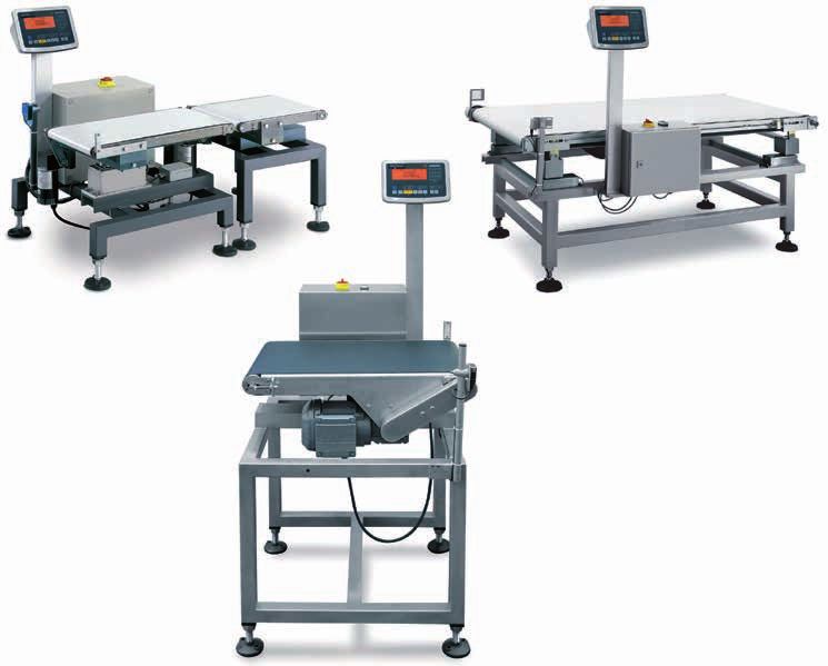
Sartorius WM Modules
Weighing in motion
Retain for later use.
Sartorius instruc-
Original operating
operating instructions.
tions
98648-009-48
98648-009-48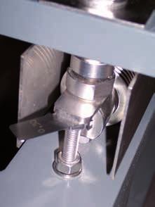
Manufacturer’s ID Label

                                           Manufacturer’s ID Label
                                           Make sure that the voltage and frequency of your power supply correspond to the
                                           ratings specified on the machine’s manufacturer’s ID label before connection and
                                           initial operation of the machine.

                                           The manufacturer’s ID label is located on the side of the control unit as well as
                                           inside the control cabinet on the left.

                                                                                           Sartorius Industrial Scales GmbH & Co. KG
                                                                                           Leinetal 2
                                                                                           37120 Bovenden, Germany

                                           Explanation of the Manufacturer’s ID Label

                                           Information                     Meaning
                                           WM                              Model
                                           aa                              Max. capacity in kg
                                           bbb.                            Transport belt dimensions and material
                                           cccccc                          Serial number
                                           ddd                             Order number
                                           eee                             Modification
                                           2xxx                            Year of manufacture

                                           To ensure correct processing, please have the following available when making
                                           telephone or written inquiries and/or placing orders:
                                           Type designation
                                           Order number and
                                           Serial number

                                           All information can be found on the manufacturer’s ID label.
                                           The manufacturer’s ID label is located on the side of the control unit as well as
                                           inside the control cabinet on the left.

2   Operating instructions Weighing in motion
Information for the User Contents
Contents 7.Operation . . . . . . . . . . . . . . . . . . . . . . . . . . . . . . . . . . . . . 42
7.1 Configuration . . . . . . . . . . . . . . . . . . . . . . . . . . . . . . 44
7.1.1 Display and Operating Terminal . . . . . . . . . . . 73
Manufacturer’s ID Label . . . . . . . . . . . . . . . . . . . . . . . . . . . . . . . 2 7.1.2 Checking the Classification Limits
Contents . . . . . . . . . . . . . . . . . . . . . . . . . . . . . . . . . . . . . . . . . . . 3 Entered in the Application Program . . . . . . . . 74
1. User Information . . . . . . . . . . . . . . . . . . . . . . . . . . . . . . . . . 4 7.1.3 Product Data Memory . . . . . . . . . . . . . . . . . . 74
1.1 About These Operating Instructions . . . . . . . . . . . . . . . . 4 7.1.4 Saving Product Data . . . . . . . . . . . . . . . . . . . . 74
1.2 Basic Information . . . . . . . . . . . . . . . . . . . . . . . . . . . . . 5 7.1.5 Loading Saved Product Data . . . . . . . . . . . . . . 74
1.3 Accompanying Documents . . . . . . . . . . . . . . . . . . . . . . 5 7.1.6 Interrupting the Saving Process or
1.4 Intended Use . . . . . . . . . . . . . . . . . . . . . . . . . . . . . . . . . 5 Deleting the Product Data . . . . . . . . . . . . . . . 74
1.5 User Group . . . . . . . . . . . . . . . . . . . . . . . . . . . . . . . . . . 6 7.1.7 Accessing Tolerance Limits and the
1.6 General Safety Instructions . . . . . . . . . . . . . . . . . . . . . . 7 Correction Factor . . . . . . . . . . . . . . . . . . . . . . 74
1.7 Basic Safety Instructions . . . . . . . . . . . . . . . . . . . . . . . . 8 7.2 Digital I/O YDO01M-IO Settings . . . . . . . . . . . . . . . . . 75
1.8 Safety Equipment . . . . . . . . . . . . . . . . . . . . . . . . . . . . 13 7.2.1 Inputs . . . . . . . . . . . . . . . . . . . . . . . . . . . . . . 75
1.9 Safety Labels on the Machine . . . . . . . . . . . . . . . . . . . 13 7.2.2 Outputs . . . . . . . . . . . . . . . . . . . . . . . . . . . . . 76
7.2.3 Correction Factor . . . . . . . . . . . . . . . . . . . . . . 76
2. Unpacking and Transport . . . . . . . . . . . . . . . . . . . . . . . . . . 14 7.2.4 Keypad . . . . . . . . . . . . . . . . . . . . . . . . . . . . . . 76
2.1 Equipment Supplied and Checking for Delivery Damage 14 7.2.5 COM 1 datProt Data Protocol Settings,
2.2 Transport Instructions . . . . . . . . . . . . . . . . . . . . . . . . . 14 – sbi SBI Standard Version . . . . . . . . . . . . . . . 76
2.3 Removing | Installing Weigh Cell Transport Lock . . . . . . 16 7.2.6 Serial Data Interface . . . . . . . . . . . . . . . . . . . . 76
3. Specifications . . . . . . . . . . . . . . . . . . . . . . . . . . . . . . . . . . . 17 8.Maintenance . . . . . . . . . . . . . . . . . . . . . . . . . . . . . . . . . . . . 78
3.1 Specifications, Performance Features WM6… . . . . . . . . 17 8.1 Cleaning . . . . . . . . . . . . . . . . . . . . . . . . . . . . . . . . . . 78
3.2 Specifications, Performance Features WM35… . . . . . . . 18 8.2 Servicing . . . . . . . . . . . . . . . . . . . . . . . . . . . . . . . . . . 80
3.3 Specifications, Performance Features WM60… . . . . . . . 19 8.2.1 Inspection After Every 500 Operating Hours . . 81
3.4 Specifications, Performance Features WM120… . . . . . . 21 8.2.2 Transport Medium . . . . . . . . . . . . . . . . . . . . . 81
Dimensional Drawings . . . . . . . . . . . . . . . . . . . . . . . . . . . . . . 23 8.2.3 Electrical Maintenance . . . . . . . . . . . . . . . . . . 82
8.2.4 Replacing the Conveyor Belt . . . . . . . . . . . . . . 83
4.Product Description . . . . . . . . . . . . . . . . . . . . . . . . . . . . . . . 29 8.2.5 Wearing or Contacting Parts . . . . . . . . . . . . . . 83
4.1 Application Range, Description . . . . . . . . . . . . . . . . . . 29 8.2.6 Replacement Parts . . . . . . . . . . . . . . . . . . . . . 83
4.1.1 Overview . . . . . . . . . . . . . . . . . . . . . . . . . . . . . . 29 8.2.7 WM35GEP + WM35IEP . . . . . . . . . . . . . . . . . 84
4.1.2 Machine Design . . . . . . . . . . . . . . . . . . . . . . . . 29
4.1.3 Functional Principle, Mode of Operation . . . . . . 30 9. Repairs . . . . . . . . . . . . . . . . . . . . . . . . . . . . . . . . . . . . . . . 87
9.1 Faults, Possible Causes and Remedies . . . . . . . . . . . . . 88
5.Installation, Assembly . . . . . . . . . . . . . . . . . . . . . . . . . . . . . 33
5.1 Operating Position|Operating Station . . . . . . . . . . . . . 33 10. Storage . . . . . . . . . . . . . . . . . . . . . . . . . . . . . . . . . . . . . . . 90
5.2 Tools and Testing Equipment . . . . . . . . . . . . . . . . . . . 33 10.1 Storage Conditions . . . . . . . . . . . . . . . . . . . . . . . . . . . 90
5.3 Mechanical Installation, Setup . . . . . . . . . . . . . . . . . . . 33
5.3.1 Prerequisites . . . . . . . . . . . . . . . . . . . . . . . . . . . 33 11. Decommissioning, Disassembly . . . . . . . . . . . . . . . . . . . . . . . . . 91
5.3.2 Areas to be Secured . . . . . . . . . . . . . . . . . . . . . 35 11.1 Disposal . . . . . . . . . . . . . . . . . . . . . . . . . . . . . . . . . . . 91
5.3.2 Setup Note . . . . . . . . . . . . . . . . . . . . . . . . . . . . 35
5.3.4 Handling the Weighing Platform . . . . . . . . . . . . 35 12. Appendix . . . . . . . . . . . . . . . . . . . . . . . . . . . . . . . . . . . . . . 92
5.3.5 Leveling the Checkweigher . . . . . . . . . . . . . . . . 35 12.1 Certificates . . . . . . . . . . . . . . . . . . . . . . . . . . . . . . . . . 92
5.4 Electrical Installation . . . . . . . . . . . . . . . . . . . . . . . . . . 36 12.1.1 Declaration of Incorporation . . . . . . . . . . . . . . 92
5.4.1 Power Connection . . . . . . . . . . . . . . . . . . . . . . 36 12.2 Glossary, List of Abbreviations . . . . . . . . . . . . . . . . . . 93
5.4.2 Installation . . . . . . . . . . . . . . . . . . . . . . . . . . . . 37 12.2.1 Customer Service, Hotline
5.4.3 Sorting Units . . . . . . . . . . . . . . . . . . . . . . . . . . 38 and Technical Support . . . . . . . . . . . . . . . . . . 97
5.4.4 Motor Cable . . . . . . . . . . . . . . . . . . . . . . . . . . . 38
6.Switching On, Initial Startup . . . . . . . . . . . . . . . . . . . . . . . . 39
The following symbols are used in these instructions:
6.1 Measures Prior to Commissioning . . . . . . . . . . . . . . . . 39
6.1.1 Inspections and Adjustments after § Indicates steps you must perform
Switching On for the First Time . . . . . . . . . . . . . 39 $ Indicates steps you must perform only under certain
6.1.2 Belt Speed . . . . . . . . . . . . . . . . . . . . . . . . . . . . 40 conditions
6.1.3 Product Recognition . . . . . . . . . . . . . . . . . . . . . 40 > Describes what happens after you have performed a
6.3.2 Weight Value Determination particular step
(Checking, Adjustment) . . . . . . . . . . . . . . . . . . . 40 – Indicates an item in a list
6.3.3 Static Weight Check . . . . . . . . . . . . . . . . . . . . . 41
6.3.4 Dynamic Weight Check . . . . . . . . . . . . . . . . . . . 41
! Indicates a hazard
Operating instructions Weighing in motion 3User Information
1. User Information Typographical Conventions
The following icons and typographical conventions make
using this document easier and provide easier navigation:
1.1 About These Operating Instructions
– The individual steps of multi-step instructions are
Purpose
sequentially numbered, e.g. 1.), 2.), 3.).
These operating instructions offer users a solid base of
They instruct you to carry out an action.
knowledge for successful use of the machine.
The operating instructions provide clear and detailed
– Courier New Characters that can be entered in input
information on the safe and correct use, maintenance and
fields using the keyboard are emphasized in this font.
care of the machine. They also include details on the
operation and configuration settings of the machine as well
– "XXXX" Main menu
as its operating options and numerous areas of application.
These operating instructions describe, among other things,
– "XXXX" Sub menu, dialog, option
all of the machine’s standard equipment functions that are
available during operation. The actual functions available
– t Options for correcting problems, faults, errors, etc.
depend on the order-specific version as each machine is
designed and planned according to its intended, future
application.
The figures and photos in this operating manual are
h User tips, useful information and notes
representative of all versions (standard and special versions)
Naturally, we are available at any time for any questions.
of the equipment.
We would also enjoy hearing any comments, criticisms or
The same applies to all actions, notes and explanations in
suggestions that you may have regarding the content of
this manual.
these operating instructions. We would also like to hear
about your experiences with using the equipment.
Target Audience
Please contact us should you encounter any problems when
This operating manual is designed for all user groups who
operating the machine or any general operational questions
handle the equipment throughout the entire lifecycle.
that are not answered by this operating manual.
It addresses all of the subjects and areas that are relevant
to these different user groups.
The content of this operating manual has been put together
with the greatest care and corresponds to our current level of
Organization
information. These operating instructions are published by
The chapter structure is chronological to the individual
Sartorius with no guarantee of any kind. We reserve the right
lifecycles and phases of the equipment. This makes it possible
to make corrections as well as technical and contextual
to selectively read individual topics and find quick answers to
changes to this operating manual at any time without
specific questions.
notification to correct typographical errors and editorial
In addition to the chapter on general safety instructions, the
inaccuracies as well as for reasons due to machine and | or
corresponding safety and warning information can also be
program upgrades.
found at the beginning of every chapter and, where
These kinds of changes will be continually incorporated into
necessary, at the beginning of each step/action concerned.
the operating manual.
The first two chapters contain general and basic specifica
tions as well as important safety instructions. Please read
these chapters carefully.
Chapters 3, 4 and 5 contain a detailed product description
including technical performance features.
Specific instructions for implementing the required steps for
machine operation are included in the following chapters.
The appendix contains important addresses, a glossary with
explanations of important abbreviations and basic terms as
well as other information.
4 Operating instructions Weighing in motionUser Information
1.2 Basic Information 1.4 Intended Use
In principle, all provisions of the General Terms and Intended Use
Conditions for Deliveries and Services of Sartorius, in their Application limits:
current version, apply. – If you use the machine in ways contrary to the order
confirmation or the technical specifications, this could
The points lead to a result that is less than optimal.
– Warranty – The machine may only be used while in full working
order, according its to intended use and while taking
– Liability into account the safety and hazard information in the
operating instructions.
– Software
– The machine | system is intended exclusively for weighing.
– Assembly It serves for weighing and classifying as well as
transporting away conveyed goods with the dimensions
of the General Terms and Conditions apply in particular to and weights stated in the specifications. Weighed products
the operation of the machine in all life phases, and we would (e.g. molded parts) are checked for compliance with a
like to take this opportunity to once again explicitly state weight tolerance. The programmed weigher classifies the
that these agreements/instructions must be observed while weighed products based on preconfigured tolerances < = >
working with the machine. and generates a potential-free signal (correct filling |
incorrect filling). The weigher will determine and output
one weight value for each weighed item.
1.3 Accompanying Documents Any other use beyond this is considered improper use.
Other documents are also valid in connection with this – The scale is a measurement instrument and must be
operating manual. treated as such. No objects may be stored atop the
weighing table. Impacts and mechanical forces on and
– Depending on the order-specific version: against the weighing platform must be absolutely avoided.
Operating instructions for the options
– The machine was designed for industrial use only.
– Spare parts information Foodstuffs | Edibles may only be weighed while packaged.
– Non-solid products can only be weighed while packaged.
– Electronics documents – The evaluation of the weighing results is the responsibility
of the machine operator.
– Mechanics documents – Location limitations:
The machine is designed to be used exclusively in closed
– Test reports rooms.
– Time-related limitations:
– Certificates Anticipated service life of the machine: No limitations.
– Intended use also includes following the operating
Safety Instructions instructions as well as all other applicable documents,
This chapter contains important information. Please read including the maintenance recommendations | instructions.
before using the equipment.
Operating instructions Weighing in motion 5User Information
Improper Use | Foreseeable Misuse 1.5 User Group
– The machine was tested at the factory and shipped in a
safe and proper condition. It is a state-of-the-art machine – Personnel who work on and operate the machine must be
and is built in accordance with recognized safety reliable, trained and aware of all safety information.
standards. Nevertheless, its use may pose bodily or physical
harm to users or third-parties as well as potentially cause – All work on electrical equipment of the machine must only
impairments to the machine itself or other material be performed by an electrician or by qualified personnel
damage. under the direction and supervision of an electrician
Any use that deviates from the use described in these according to electrical engineering regulations.
operating instructions is considered improper use in terms
of foreseeable misuse, in particular, use of the machine – Qualified personnel are those involved in the setup,
to transport people or other beings. Sartorius is not installation, commissioning and operation of the machine
responsible for any damages resulting from this. who have the appropriate qualifications to carry out these
tasks.
– Only the product(s) stipulated in the contract may be used
in the machine because this is the only way to ensure – A qualified electrician is a person who has training,
optimal and problem-free function of the machine. knowledge and experience regarding the latest standards/
Product changes or product condition changes not agreed regulations for electronics and electrical engineering and
to by us can limit the performance of the machine because who can evaluate the assigned work and recognize
it has been customized to optimally meet your possible dangers.
requirements.
– Personnel in training must be supervised.
– The machine is not suitable for use in potentially explosive
environments. – The buyer is responsible for training personnel in the use
of the machine. He must ensure that operating personnel
are familiar with the safety regulations and the correct
handling procedures.
– Safety training must be repeated at regular intervals.
– Technicians must have access to the required documents
and instructions and be trained accordingly.
– The responsibilities for the different tasks on the machine
must be clearly defined and observed. as uncertainty
concerning the same could endanger user safety. If the
machine is used by several persons, draw up a detailed
workstation allocation plan.
– All claims under the manufacturer’s warranty are forfeited
in event of misuse or operation by unauthorized persons.
– The buyer is responsible for any injuries or damage to
the machine that result from improper handling of the
machine or failure to follow the safety rules.
6 Operating instructions Weighing in motionUser Information
1.6 General Safety Precautions Operator Responsibilities
– The operator is responsible to ensure and implement all
General safety instructions are not associated with any measures to prevent accidents, occupational illness, work-
specific activities and make reference to basic safety-related related health hazards and measures for user-friendly
information only. This basic information must be taken into design of work activities.
account throughout all life phases of the machine. For this
reason, it is summarized at the beginning of these operating – The operator is obligated to instruct the personnel
instructions. regarding special operational aspects and requirements.
During the development, construction and design of the – The operator also has to ensure that the electrical
machine, special attention was given to ensuring safe machinery and operating equipment are operated
operation, problem-free maintenance and easy cleaning. according to electrical engineering regulations.
Despite these measures, the following safety instructions
must be observed to avoid injuries or death. – If a fault is detected in electrical machinery or electrical
Failure to comply with the safety instructions will forfeit operating equipment, i.e. if it does not correspond or
any claims to compensation for damages. no longer corresponds to the electrical engineering
regulations, the operator must ensure that the fault is
– The machine may only be used while in full working corrected immediately. If this causes an immediate hazard,
order, according its to intended use and while taking he must ensure that the electrical machinery or electrical
into account the safety and hazard information in the equipment is not used while in a defective state.
operating instructions.
– The operator also has to ensure that the electrical
– Mandatory intervals and/or intervals listed in the machinery and operating equipment are tested according
operating instructions for recurring tests| inspections to electrical engineering regulations. Disruptions,
and maintenance work must be observed. especially those that could adversely affect safety, must
be corrected immediately.
Accident Prevention Regulations, Company | Regional |
National Requirements Technical Documents
– Any existing national rules and regulations regarding – Please keep these operating instructions and all associated
accident prevention and any internal company documents where they can be accessed immediately if
occupational, operational and safety regulations must required. This is the only way to ensure that any problems
be observed. that occur can be corrected immediately.
– The accident prevention regulations for electrical – Should these operating instructions be lost, please order
equipment from the employers’ liability insurance replacement documents from us.
association “Electrical Machinery and Operating
Equipment according to BGV A2" (previously VBG 4) – If the machine is sold or transferred, the operating
is binding in Germany. In all other countries, the instructions and all associated documents must be passed
corresponding national regulations, laws and requirements on to the subsequent owner.
must be followed.
– Personnel must have read and understood the operating
– All currently applicable workplace health and safety instructions before commencing work on or operating this
regulations as well as all relevant safety guidelines must machine. Sartorius is not liable for any damages due to
be strictly adhered to when working on the machine. non-compliance with this manual.
– If work instructions, the sequence of work instructions,
safety instructions or safety labels are not observed, the
safe operation of the machine cannot be guaranteed and
all claims for damages will become void.
Operating instructions Weighing in motion 7User Information
Safety of Personnel 1.7 Basic Safety Instructions
– If required, personal protective equipment should be Basic safety instructions are the most important safety
worn (PPE). The operator is responsible for selecting and information divided by subject, valid for several different
providing suitable protective clothing (temperature) and activities, which must be taken into account in all life phases
personal protective equipment. of the machine. The purpose of these instructions is to
fundamentally prepare you for safe operation of the machine
– The machine contains mandatory signs regarding the and subsequently not having to repeat these instructions
use of PPE if required. throughout the document.
The machine should only be operated with sufficient
illumination.
Signal Words, Pictograms and Symbols Used
Signal Words
All safety-related instructions are marked with one of the signal words listed in the table below.
Signal words indicate the severity of the danger involved when measures for preventing hazards are not followed.
Signal word field 1. Criterion: 2. Criterion: Meaning
Consequences Probability
Death|Severe injury Imminent Danger indicates that death or severe, irreversible personal
DANGER
(irreversible) injury will occur if appropriate safety measures are not
observed.
Death|Severe injury Possible Warning indicates that death or severe, irreversible injury
WARNING
(irreversible) may occur if appropriate safety measures are not observed.
Mild injury (reversible) Possible Caution indicates that minor, reversible injury or damage to
CAUTION
property may occur if appropriate safety measures are not
observed.
ATTENTION Property damage Possible Attention indicates that damage to property may occur if
appropriate safety measures are not observed.
8 Operating instructions Weighing in motionUser Information
Danger Symbols, Prohibition and Mandatory Signs
Contrary to the signal word, danger symbols, prohibition and mandatory signs
indicate the type but not the severity of the hazard.
Danger symbols, prohibition and requirement signs warn against possible injuries.
Follow all measures that are so marked in order to avoid injuries or death.
All danger symbols are always used in conjunction with a signal word.
Symbol Meaning
Warning against a hazard area
Warning against hand injuries
Warning against dangerous electrical voltage
Warning against a slip hazard
Warning against an entanglement hazard
Prohibition for people with pacemakers
Design and Contents
Danger symbol Type and source of danger, danger type,
name of danger
Consequence(s) of non-compliance | when danger occurs
Danger sign with Measure(s) to guard against danger,
SIGNAL WORD possible actions to be taken
Operating instructions Weighing in motion 9User Information
Electrical Hazards
Electrical hazard during all work on the machine:
– Assembly and installation
– Commissioning
– Cleaning and maintenance
WARNING
 – Service and repairs
– Disassembly
The voltages at the machine can lead to serious
injuries that can be deadly under some circumstances and | or damage the machine.
Before any work is performed on the machine, the machine itself as well as any
upstream or downstream components must be disconnected from power in
accordance with VDE guidelines.
Interrupt the compressed air supply (optional).
Take all steps necessary to secure the equipment against unauthorized power-up.
Electrical hazard when opening the machine.
The voltages at the machine can lead to serious
injuries that can be deadly under some circumstances and | or damage the machine.
WARNING

The main switch must be set to “OFF” before opening the control cabinet.
The control cabinet must be securely locked after completion of the work.
The control cabinet must be securely locked during normal operation.
The machine may only be opened, installed and connected by trained and qualified
personnel.
Electrical hazard to personnel touching parts that are energized due to faults.
Electrical hazard from the application of external high voltage (incorrect operation).
The voltages at the machine can lead to serious injuries that can be deadly under
WARNING some circumstances and | or damage the machine.

External high voltage can cause electrical shocks which can lead to burns, injuries
and death in some circumstances.
All metallic parts that can be touched by the operator are integrated into the
grounding conductor system.
The grounding conductor system must always be properly connected by the
operator.
The grounding conductor system of the entire machine must be inspected on
a regular basis at intervals to be specified by the operator.
Electrical hazard due to electrostatic events, i. e. sparks or disruptive discharges
resulting from a high potential difference in an electrically insulated material that
cause a very brief high electrical current pulse.
CAUTION Injuries due to electrical discharges and | or damage to electronic components.
Use only transport media approved by Sartorius.
Work on electrical components may only be performed by a qualified electrician.
10 Operating instructions Weighing in motionUser Information
Mechanical Dangers
Danger from an unexpected startup or functional process due to:
– Intended machine functions
– Control errors and|or operating errors.
CAUTION Injuries from shearing action.
Injury from being caught and entangled, e. g. by the transport medium.
Injuries from being crushed and hit.
Any rejection device present must be secured through physical measures in such
a way that it is not possible to reach into the rejection area.
If it is not possible to secure the rejection area, it must be ensured that only
personnel with appropriate safety training is permitted to operate the machine.
The operators must have read and understood the technical documents.
Danger from electromagnetic fields due to a lack of electromagnetic
compatibility (EMC).
Unexpected or faulty function sequences.
CAUTION Disruptions in the surrounding machines.
EMC-compliant design of the machine.
EMC testing of the machine.
Danger from connection and transition points between the machine and customer-
supplied equipment.
Injuries from hands being crushed.
CAUTION Hazard areas must be secured by the operator.
Transition points must be designed safely: It must not be possible to reach into
such areas, and if this cannot be prevented through physical measures, it must be
prevented by means of safety equipment.
Danger from pieces of clothing getting caught on or entangled
in moving parts or machine transport media.
Injuries from clothing being entangled.
CAUTION Closely fitting clothing reduces the risk of clothing being caught or wound up.
For all work: Wear safety shoes and closely fitting clothing.
Hair and jewelry must be worn such that they cannot be entangled by moving
parts.
If required, personal protective equipment should be worn (PPE).
Slipping, falling and tripping hazards due to untidy work areas, objects left lying
around, dirty or wet floors, etc.
Injuries from slipping, falling, tripping.
CAUTION Ensure appropriate workplace instructions and monitoring to ensure that the work
area is always clean and tidy.
Operating instructions Weighing in motion 11User Information
ATTENTION
Damage from modifications and changes to the machine.
Damage and | or functional impairments to the machine.
Modifications and changes to the machine and the associated safety equipment,
programmable control systems and any hardware or software are solely the
responsibility of the operator.
Sartorius accepts no liability for personal injuries or material damages.
Our products may only be used with original accessories | original spare parts and/or
accessories and spare parts approved by Sartorius because they have been tested for
reliability, safety and suitability with our machines.
Thermal Dangers
Danger from hot surfaces or products.
Skin burns.
Do not reach into the product flow.
CAUTION Observe warning signs.
Biological or Microbiological Dangers
Hygienic danger from contamination due to product deposits and the collection of
residue with microbial contaminations.
Health risks from product contamination due to product deposits and the collection
CAUTION of residue with microbial contaminations.
Health risk from biological or microbiological substances.
Health risk from the consumption of contaminated products.
Functional impairments to the machine.
Follow the cleaning instructions, in particular the specified cleaning intervals.
Careful inspection of the cleaning results.
Regular inspection of the machine by qualified personnel.
Hygienic danger from product contamination due to contact with operating
materials (e.g. fats, oils).
Health risk due to contamination of the product.
CAUTION Injuries from slipping, falling, tripping.
Regular maintenance and inspection of the machine for leaking lubricants.
Regular inspection of the condition of bearings. Because the functioning of the
weigher depends heavily on the condition of the bearings, malfunctions should be
evident to the operator even in the case of faulty maintenance.
12 Operating instructions Weighing in motionUser Information
1.8 Safety Equipment
Possible dangers must be prevented as much as possible through the use of safety
equipment.
Danger from unsafe, faulty or missing safety equipment in all life phases of the
machine.
Serious or fatal injuries and|or damage to the machine.
WARNING Never start the machine if safety equipment is missing or defective.
The safety equipment must be regularly inspected for secure fastening, function
and completeness.
Repair or correct defective safety equipment and install missing safety equipment.
Safety equipment must not be changed, circumvented or turned off.
All protective panels and covers removed for cleaning, maintenance, or repair work
must be re-attached/re-installed before the machine is returned to operation.
The operator is responsible for the proper functioning of safety equipment.
Check the safety equipment:
– At the start of every work shift (in case of interrupted operation)
– Once weekly (during continuous operation)
– After all maintenance, inspection or repair work
Check for:
– Proper condition
– Required position/orientation
– Secure attachment
– Required function
1.9 Safety Labels on the Machine
– The instructions found on safety labels on the machine must be complied with
under all circumstances.
– Safety instructions in|on the machine must always be kept legible and complete
through the entire time the machine is in operation. If a safety label begins to
fade or is damaged during the service life of the machine, a new label must be
ordered immediately. Whenever labels are no longer easily legible at first glance,
the machine must be taken out of service until new labels can be attached.
Do not lift
Do not exert any force on the weighing belt by lifting, pushing or pulling it. This
can lead to permanent damage to the weigh cell and/or reduced accuracy of the
weighing equipment.
The warning label (20 mm diameter) is fastened to the plate in front of the weigh
cell, behind the front cover.
Operating instructions Weighing in motion 13Unpacking and Transport
2. Unpacking and Transport
2.1 Equipment Supplied and Checking for Delivery Damage
The equipment supplied should be inspected for transport damage and for
completeness to ensure proper functioning of the machine.
The following documents|accessories are included by default in the machine
delivery package:
– Depending on the order-specific version: Operating instructions for the options
– Electronics documents
– Certificates
If you also ordered accessories, consumables, etc., check that they are present and
complete.
If something is missing, please contact Sartorius, Goettingen.
The check for delivery damage includes:
– Visible damage to the machine
– Visible damage to peripheral devices
– Visible damage to cables, etc.
– The condition of the signage on the machine
Any transport damage should be immediately reported to the shipping agent.
2.2 Transport Instructions
Danger from loads or machine parts that may tilt, tip over or fall during movement
or lifting of the machine.
Danger of the machine tipping during transport due to elevated center of gravity.
WARNING Serious injuries and | or damage to the machine.
Transport should only be carried out by qualified personnel.
Personal protective equipment must be worn during transport.
The machine must always be secured against falling during transport.
Always take note of the center of gravity when transporting the machine.
The machine may only be transported in an upright, standing position.
Never stand under a suspended load.
The machine may only be transported by appropriately authorized persons and
using a forklift or hand lift.
Unfasten the machine from the pallet or the box floor, lift it with a forklift and
then transport it to the installation site using a forklift or hand lift.
Proper protection should be used to avoid contact between the lift forks and the
weigher frame.
Only place the machine on level surfaces.
14 Operating instructions Weighing in motionUnpacking and Transport
ATTENTION
Damage from improper movement|transport of the machine.
Damage to the machine|weigh cell.
Impacts and mechanical forces on and against the transport platform must be
absolutely avoided.
When transporting the machine, ensure that the checkweigher is only carried using
the brackets of the lower base.
No forces may be exerted on the transport platform.
Do not lift or push on the transport platform or lift the machine by the transport
system.
ATTENTION
Damage from movement|transport due to plug connections that have not been
disconnected.
Damage to cables and connections.
Before transporting, disconnect all electrical plug connections between the machine
and any upstream/downstream machinery.
Disconnect the machine from the power supply prior to transport.
Transport Lock
The transport lock for the weigh cell was attached at the factory for the transport
of the machine.
ATTENTION
Damage from movement | transport due to vibrations
with an unattached weigh cell transport lock.
Damage to the weigher frame and the weigh cell.
The transport lock overload protection (screws) must be installed every time the
machine is transported.
ATTENTION
Damage due to incorrect sequence and positioning of
screws when attaching the transport lock.
Damage to the machine.
The screw positions and the sequence of their installation must be observed,
and the installation must be carried out as illustrated in the corresponding
figures in the chapter “Installing the Weigh Cell Transport Lock.”
Operating instructions Weighing in motion 15Unpacking and Transport
2.3 Removing|Installing the Weigh Cell Transport Lock
Load receptors for devices WM6..., WM35GEP... and WM35IEP.. are secured using
1 overload protection.
0,3 mm Load receptors for devices WM60..., WM120... and module WM35LFP... are secured
using 4 overload protection units.
The overload protection units are removed after the machine has been set up and
before commissioning.
Loosen and remove the covers (SW 13 and/or 19).
Using the supplied metal strip
WM35GEP…, WM35IEP… (thickness: 0.3 mm) spacing (0.3 mm)
WM35LFP… (thickness: 0.3 mm) spacing (0.3 mm)
WM60… (thickness: 0.3 mm) spacing (0.3 mm)
WM120… (thickness: 0.3 mm) spacing (0.3 mm)
set the spacing between the screw and the load receptors. Secure the setting using
the locknut.
In normal operation, the air gap set by the metal strip is used as an overload
protection.
Note:
The metal strip is located in a PE pouch in the control cabinet.
Replace covers and re-secure the screws.
Before transporting the machine, make sure that the load receptors are secured
using the overload protection (screws).
Transport to the Installation Site
Never lift the machine at the transport belt!
ATTENTION Only use the sling points (see image) for transport.
When you operate the machine for the first time, after internal transport or after
a long idle time, you must carry out test runs in all available machine operating
modes.
Test the basic function of the machine and the function of all machine options
using products.
16 Operating instructions Weighing in motionSpecifications 3. Specifications 3.1 WM6… Specifications, Performance Features The results that can be achieved in practice, e.g. for the standard deviation attributable to measurement error or the throughput depend on the respective application and therefore should not be thought of as absolute values. The precise design of the delivered machine is defined in the order confirmation. Characteristic Information WM module WM6DCP.. WM6ECP.. WM6EDP.. WM6FCP.. WM6FDP.. Weighing capacity (max. cap.) [g] 25 g – 6,000 25 g – 6,000 25 g – 6,000 25 g – 6,000 25 g – 6,000 Max. product weight [g] 6,000 6,000 6,000 6,000 6,000 Dynamic accuracy ± [g]
Specifications

3.2 WM35… Specifications, Performance Features

The results that can be achieved in practice, e.g. for the standard deviation attributable to measurement error or the throughput
depend on the respective application and therefore should not be thought of as absolute values.
The precise design of the delivered machine is defined in the order confirmation.

Characteristic                                   Information
WM module                                        WM35GEP…                     WM35IEP…                     WM35LFP…
Weighing capacity (max. cap.) [g]                25 – 35,000                  25 – 35,000                  25 – 35,000
Max. product weight [g]                          35,000                       35,000                       35,000
Dynamic accuracy ± [g]                           < 25                         < 25                         < 25
                                                 Depends on product, throughput and ambient conditions
Throughput [items/min.]                          55                           42                           31
                                                 Depends on product, permissible zone of indecision and ambient conditions
Speed ranges [m/min]                             18 – 38
Center-to-center distance [mm]                   600                          800                          1000
Conveyor belt width [mm]                         400                          400                          500
Roller diameter [mm]                             60                           60                           60
Transport medium                                 Belt                         Belt                         Belt
Drives                                           Maintenance-free 230 V-AC Spiroplan drive motor, motor control via frequency
                                                 converter
Connected voltage                                230 VAC (+10 %| –15 %); 50|60 Hz (L1, N, PE)
Power consumption                                Approx. 600 VA
Conveyor direction                               Right to left or left to right
                                                 (please indicate when ordering)
Operating height [mm]                            450... 1,100 (adjustable in 50 mm frame), adjustment range of feet: ± 25 mm.
Floor clearance [mm]                             100 (± 25)
Temperature range [°C]                           –10 to +40
Permissible operating temperature                +2 to +40 (MID +5 to +40)
range [°C]
Product temperature [°C]                         –10 to +60 (belt)
Protection class                                 IP 65
Equipment safety                                 Design meets the requirements of EC Directive 2006|42|EC (Machines)
Dimensions                                       See dimensional drawings
Weigher frame material                           Powder-coated steel RAL 7043, optional stainless steel 1.4301
Weight                                           Approx. 90 kg
Airborne noise emission                          The A-weighted equivalent sound pressure level emitted in the working area of this
                                                 machine is less than 80 db(A).
Interfaces                                       RS-232, optional RS-422, RS-485, Ethernet, Profibus
Outputs                                          1 output for belt start/stop (potential-free two-way contact)

18        Operating instructions Weighing in motion
Specifications
3.3 WM60… Specifications, Performance Features
The results that can be achieved in practice, e.g. for the standard deviation attributable to measurement error or the throughput
depend on the respective application and therefore should not be thought of as absolute values.
The precise design of the delivered machine is defined in the order confirmation.
Characteristic Information
WM module WM60MHE… WM60OHE… WM60RHE…
Weighing capacity (max. cap.) [g] 25 – 60,000 25 – 60,000 25 – 60,000
Max. product weight [g] 60,000 60,000 60,000
Dynamic accuracy ± [g] < 50 < 50 < 50
Depends on product, throughput and ambient conditions
Throughput [items/min.] 31 26 23
Depends on product, permissible zone of indecision and ambient conditions
Speed ranges [m/min] 18 – 38
Conveyor belt length [mm] 1,100 1,300 1,500
Conveyor belt width [mm] 700 700 700
Roller diameter [mm] 70 70 70
Transport medium Belt Belt Belt
Drives Maintenance-free 230 V-AC Spiroplan drive motor, motor control via
frequency converter
Connected voltage 230 VAC (+10 %| –15 %); 50|60 Hz (L1, N, PE)
Power consumption Approx. 900 VA
Conveyor direction From right to left or left to right (please indicate when ordering)
Operating height [mm] 450... 1,100 (adjustable in 50 mm frame), adjustment range of feet: ± 25 mm.
Floor clearance [mm] 100 (± 25)
Temperature range [°C] –10 to +40
Permissible operating temperature +2 to +40 (MID +5 to +40)
range [°C]
Product temperature [°C] -10 to +60 (belt)
Protection class IP 65
Equipment safety Design meets the requirements of EC Directive 2006|42|EC (Machines)
Dimensions See dimensional drawings
Weigher frame material Powder-coated steel RAL 7043, optional stainless steel 1.4301
Weight Approx. 180 kg
Airborne noise emission The A-weighted equivalent sound pressure level emitted in the working area of this
machine is less than 80 db(A).
Interfaces RS-232, optional RS-422, RS-485, Ethernet, Profibus
Outputs 1 output for belt start/stop (potential-free two-way contact)
Operating instructions Weighing in motion 19Specifications
Characteristic Information
WM module WM60RKE.. WM60TKE.. WM60WKE.. WM60YKE..
Weighing capacity (max. cap.) [g] 25 – 60,000 25 – 60,000 25 – 60,000 25 – 60,000
Max. product weight [g] 60,000 60,000 60,000 60,000
Dynamic accuracy ± [g] < 50 < 50 < 50 < 50
Depends on product, throughput and ambient conditions
Throughput [items/min.] Max. 23 Max. 20 Max. 18 Max.17
Depends on product, permissible zone of indecision and ambient conditions
Speed ranges [m/min] 18 – 38
Conveyor belt length [mm] 1,500 1,700 1,900 2,100
Conveyor belt width [mm] 900 900 900 900
Roller diameter [mm] 70 70 70 70
Transport medium Belt Belt Belt Belt
Drives Maintenance-free 230 V-AC Spiroplan drive motor, motor control via
frequency converter
Connected voltage 230 VAC (+10 %| –15 %); 50|60 Hz (L1, N, PE)
Power consumption Approx. 900 VA
Conveyor direction From right to left or left to right (please indicate when ordering)
Operating height [mm] 450... 1,100 (adjustable in 50 mm frame), adjustment range of feet: ± 25 mm.
Floor clearance [mm] 100 (± 25)
Temperature range [°C] –10 to +40
Permissible operating temperature +2 to +40 (MID +5 to +40)
range [°C]
Product temperature [°C] –10 to +60 (belt)
Protection class IP 65
Equipment safety Design meets the requirements of EC Directive 2006|42|EC (Machines)
Dimensions See dimensional drawings
Weigher frame material Powder-coated steel RAL 7043, optional stainless steel 1.4301
Weight Approx. 180 kg
Airborne noise emission The A-weighted equivalent sound pressure level emitted in the working area of this
machine is less than 80 db(A).
Interfaces RS-232, optional RS-422, RS-485, Ethernet, Profibus
Outputs 1 output for belt start/stop (potential-free two-way contact)
20 Operating instructions Weighing in motionSpecifications
3.4 WM120… Specifications, Performance Features
The results that can be achieved in practice, e.g. for the standard deviation attributable to measurement error or the throughput
depend on the respective application and therefore should not be thought of as absolute values.
The precise design of the delivered machine is defined in the order confirmation.
Characteristic Information
WM module WM120MHE… WM120OHE… WM120RHE…
Weighing capacity (max. cap.) [g] 25 – 120,000 25 – 120,000 25 – 120,000
Max. product weight [g] 120,000 120,000 120,000
Dynamic accuracy ± [g] < 50 < 50 < 50
Depends on product, throughput and ambient conditions
Throughput [items/min.] Max. 31 Max. 26 Max. 23
Depends on product, permissible zone of indecision and ambient conditions
Speed ranges [m/min] 18 – 38
Conveyor belt length [mm] 1,100 1,300 1,500
Conveyor belt width [mm] 700 700 700
Roller diameter [mm] 70 70 70
Transport medium Belt Belt Belt
Drives Maintenance-free 230 V-AC Spiroplan drive motor, motor control via frequency
converter
Connected voltage 230 VAC (+ 10 %| –15 %); 50|60 Hz (L1, N, PE)
Power consumption Approx. 900 VA
Conveyor direction From right to left or left to right (please indicate when ordering)
Operating height [mm] 450... 1,100 (adjustable in 50mm frame), adjustment range of feet: ± 25 mm.
Floor clearance [mm] 100 (± 25)
Temperature range [°C] –10 to +40
Permissible operating temperature +2 to +40 (MID +5 to +40)
range [°C]
Product temperature [°C] –10 to +60 (belt)
Protection class IP 65
Equipment safety Design meets the requirements of EC Directive 2006|42|EC (Machines)
Dimensions See dimensional drawings
Weigher frame material Powder-coated steel RAL 7043, optional stainless steel 1.4301
Weight Approx. 180 kg
Airborne noise emission The A-weighted equivalent sound pressure level emitted in the working area of this
machine is less than 80 db(A).
Interfaces RS-232, optional RS-422, RS-485, Ethernet, Profibus
Outputs 1 output for belt start/stop (potential-free two-way contact)
Operating instructions Weighing in motion 21Specifications
Characteristic Information
WM module WM120RKE.. WM120TKE.. WM120WKE.. WM120YKE..
Weighing capacity (max. cap.) [g] 25 – 120,000 25 – 120,000 25 – 120,000 25 – 120,000
Max. product weight [g] 120,000 120,000 120,000 120,000
Dynamic accuracy ± [g] < 50 < 50 < 50 < 50
Depends on product, throughput and ambient conditions
Throughput [items/min.] Max. 23 Max. 20 Max. 18 Max.17
Depends on product, permissible zone of indecision and ambient conditions
Speed ranges [m/min] 18 - 38
Conveyor belt length [mm] 1,500 1,700 1,900 2,100
Conveyor belt width [mm] 900 900 900 900
Roller diameter [mm] 70 70 70 70
Transport medium Belt Belt Belt Belt
Drives Maintenance-free 230 V-AC Spiroplan drive motor, motor control via
frequency converter
Connected voltage 230 VAC (+10 %|–15 %); 50|60 Hz (L1, N, PE)
Power consumption Approx. 900 VA
Conveyor direction From right to left or left to right (please indicate when ordering)
Operating height [mm] 450... 1,100 (adjustable in 50mm frame), adjustment range of feet: ±25 mm.
Floor clearance [mm] 100 (± 25)
Temperature range [°C] –10 to +40
Permissible operating temperature +2 to +40 (MID +5 to +40)
range [°C]
Product temperature [°C] –10 to +60 (belt)
Protection class IP 65
Equipment safety Design meets the requirements of EC Directive 2006|42|EC (Machines)
Dimensions See dimensional drawings
Weigher frame material Powder-coated steel RAL 7043, optional stainless steel 1.4301
Weight Approx. 180 kg
Airborne noise emission The A-weighted equivalent sound pressure level emitted in the working area of this
machine is less than 80 db(A).
Interfaces RS-232, optional RS-422, RS-485, Ethernet, Profibus
Outputs 1 output for belt start/stop (potential-free two-way contact)
22 Operating instructions Weighing in motionDimensional Drawings
Dimensional Drawings
WM6L
Space requirement
for opening door of
control cabinet
Operating instructions Weighing in motion 23Dimensional Drawings
WM6R
Space requirement
for opening door of
control cabinet
24 Operating instructions Weighing in motionDimensional Drawings
Transport belt length TL [mm] Center-to-center distance Belt width BB [mm]
AA-WB [mm]
WM6DCP-I000Q 330 Approx. 300 200
WM6ECP-I000Q 430 Approx. 400 200
WM6EDP-I000Q 430 Approx. 400 300
WM6FCP-I000Q 530 Approx. 500 200
WM6FDP-I000Q 530 Approx. 500 300
WM35GEP|IEP
Space requirement
for opening door of
control cabinet
Conveyor belt width BB Transport belt length TL [mm] Center-to-center
[mm] distance AA [mm]
WM35GEP-I000Q 400 660 600
WM35IEP-I000Q 400 860 800
Operating instructions Weighing in motion 25Dimension Drawings
WM35LFP
Space requirement
for opening door
of control cabinet
Conveyor belt width BB [mm] Transport belt length TL [mm] Center-to-center distance AA [mm]
WM35LFP-I000Q 500 1,060 1,000
26 Operating instructions Weighing in motion
WM60|120
Space require-
ment for opening
door of control
cabi net
Conveyor belt width BB [mm] Transport belt length TL [mm] Center-to-center distance AA [mm]
WM60MHE-I000Q 700 1,100 1,030
WM60OHE-I000Q 700 1,300 1,230
WM60RHE-I000Q 700 1,500 1,430
WM60RKE-I000Q 900 1,500 1,430
WM60TKE-I000Q 900 1,700 1,630
WM60WKE-I000Q 900 1,900 1,830
WM60YKE-I000Q 900 2,100 2,030
Operating instructions Weighing in motion 27Dimension Drawings
Conveyor belt width BB [mm] Transport belt length TL [mm] Center-to-center distance AA [mm]
WM120MHE-I000Q 700 1,100 1,030
WM120OHE-I000Q 700 1,300 1,230
WM120RHE-I000Q 700 1,500 1,430
WM120RKE-I000Q 900 1,500 1,430
WM120TKE-I000Q 900 1,700 1,630
WM120WKE-I000Q 900 1,900 1,830
WM120YKE-I000Q 900 2,100 2,030
28 Operating instructions Weighing in motionProduct Description
4. Product Description
4.1 Application Range, Description
4.1.1 Overview
The WM modules WM6 | 35 | 60 | 120, when used in conjunction with the WM 22
evaluation electronics, combine to form a checkweigher for determining the weight
or completeness of products.
All WM modules offer a variety of interfaces. This enables smooth, centralized
integration of WM modules into existing or new quality assurance systems, for
100% traceability in production monitoring.
4.1.2 Machine Design
A WM module consists of the following design elements:
§ Weigher frame with control unit
§ Weigh cell
§ Indicator
§ Control electronics
Optional structural components include, for example:
§ Touch guard (optional)
§ Reject or sorting mechanism (optional)
Products are transported via a conveyor belt and weighed while passing over the
weighing belt. The weighing belt and the customer infeed and outfeed belts must
all have the same belt speed so that the parts to be checked are transferred
smoothly to the weighing belt and then moved away again.
The individual components are described in more detail below:
Weigher frame with control unit
Solid tower housing of steel, powder-coated, protection class IP 65.
The weigher frame is available in different heights so that you can implement
different transport heights. The desired working height can be adjusted in
increments of 50 mm, from 450 to 1100 mm (special heights available upon
request). Threaded leveling feet are provided for fine adjustment of the height.
The display and operating terminal is built into the control unit.
Weigh cell
Strain gauge weigh cells from Sartorius, characterized by the following features:
– Maximum precision and extremely short stabilization time
– Maximum stability, robustness and overload protection
– State-of-the-art electronics with digital signal processing for particularly effective
filtering
Operating instructions Weighing in motion 29Product Description
Transport System
The products are transported by the weighing belt.
A conveyor belt serves here as the transport medium.
The weighing belt is driven by a frequency inverter controlled, maintenance-free
230 V AC drive motor. The force transmission is implemented by drive belts.
Control Electronics
The control unit is integrated into a powder-coated control cabinet that is accessible
from the back or front depending on customer requirements.
The terminals for the power supply, small control system, mains adapter and
frequency inverter are also installed in the control unit.
The main switch and the display and operating terminal are installed in easily
accessible locations.
The WM and X4 (optional) evaluation electronics are available for selection.
The Start|Stop key for the transport medium is located on the top of the control
cabinet.
4.1.3 Functional Principle, Mode of Operation
Weighing takes place automatically in a dynamic state (throughput operation) or
static state (start-stop operation) without intervention by the operating personnel.
The products to be weighed are transported to the weighing belt by a customer
infeed belt. The weight value is determined as follows when the product crosses the
weighing belt.
The product nears the weighing section of the weighing belt. The product is picked
up by the transport belt. The internally determined weight value changes from “0"
increasing to a weight value “G."
The product lies completely on the weighing belt. The value determined by the
weighing platform is higher at this moment than the actual weight value of the
product.
This behavior is called overswing.
The product is now transported by the transport belt over the weighing section. The
continuously determined weight values are increasingly identical. This determined
weight value corresponds to the actual weight value of the product.
The product breaks the light barrier. The weight value determined at this moment is
shown on the display of the WM indicator and output via the interface. At the same
time, the classification outputs for lighter, heavier and equal are queried by the PLC
and a potential-free contact is opened corresponding to the determined
classification.
This can then be processed further, e.g. for sorting control.
30 Operating instructions Weighing in motionProduct Description
Product distance
The next product nears the transport belt.
Important!
h
Two products may not be conveyed at the same time over the transport belt and
thus over the weighing section.
In addition, a safety factor of 10% of the length of the weighing section should be
added.
This is how you determine the product center-to-center distance:
The product center-to-center distance corresponds to the distance between the
product front edge to the product front edge or the weighing belt length + 10% of
the weighing belt length.
The product leaves the transport belt, the last determined weight value remains on
the display until the next weight value is determined and displayed.
The measurement process for determining the weight makes use of a load sensor
with a strain gauge.
The introduction of force takes place directly via the conveyor belt to the weigh
cell.
The weight force to be measured deforms the strain gauge. The resulting resistance
change is converted into an equivalent weight value together with a mass unit by
the evaluation unit of the WM indicator and shown on the display.
Equipment
The basic equipment and options are listed in the following:
Operating instructions Weighing in motion 31Product Description
Feature, Function Versions Available, Explanation, Description
Checkweigher type WM6 | 35 | 60 | 120
Weighing system 6 kg | 35 kg | 60 kg | 120 kg. Weighing systems are equipped with 1 or 4 DMS systems.
Indicator WM indicator
X4 (optional)
Dialog language indicator 5 standard languages (de, en, fr, it, es), additional languages
Weight display Gross weight
Operational display Weight display
Conveyor direction Left → right, right ← left
Transport height [mm] 450 – 1100 – Special heights upon request
Speed range [m/min] 18 – 38
Protection class (IP) IP 65
Rejection system Optional only
Blower devices (equipment), pushers (equipment), version depending on the
application, controlled via customer rejection systems
Dust cover Optional only
Light barrier Reflex light barrier,
Classification 3 Classification limits
Classification display Optional only
Signal lamp 3-way
Signal lamp 3-way and horn
Interfaces RS-232
Optional only
Ethernet
Profibus
RS-422
Interface for individual weight value output for external evaluation and connection to
SQC systems
All interfaces listed here are non-reactive and do not require a fuse.
Data transmission
Individual weight Serial interface RS-232, RS-422 (optional),
Field bus Profibus DP (optional)
Control functions
Completeness checks
Measuring accuracy check
Documentation
Format Paper (1-fold)
Operating instructions 5 standard languages (de, en, fr, it, es), additional languages
Rejection and Sorting Equipment
Optional rejection equipment (blower devices, pushers, rejection arms and ejection switches) and sorting equipment (sorting
gates and line separators) can be controlled on the outfeed belt.
The selection of rejection|sorting equipment depends on the product, the throughput and application.
32 Operating instructions Weighing in motionYou can also read