How to build a new eco-friendly supermarket - Report 3 - R744.com
←
→
Page content transcription
If your browser does not render page correctly, please read the page content below
How to build a
new eco-friendly
supermarket

Report 3
Public report

for the project:

SuperSmart - Expertise hub for a market
uptake of energy-efficient supermarkets
by awareness raising, knowledge transfer
and pre-preparation of an EU Ecolabel

Lead authors:

Hanne Kauko, SINTEF
Karoline Husevåg Kvalsvik, SINTEF
Armin Hafner, NTNU

Publishing & Communication:

Nina Masson, shecco

More information:

www.supersmart-supermarket.org
info@supersmart-supermarket.org

October 2016

SuperSmart is funded by the European Union, under the Horizon 2020
Innovation Framework Programme, project number 696076.
Page 3 of 54

                                                                  Table of Contents
                                                                                                                                                                        Page

EXECUTIVE SUMMARY ....................................................................................................................................... 5
1      INTRODUCTION ......................................................................................................................................... 7
       1.1        Introduction to How to build a new eco-friendly supermarket ..................................................7
2      BUILDING DESIGN...................................................................................................................................... 9
       2.1        Size, shape and outer design ............................................................................................................ 9
       2.2        The building envelope........................................................................................................................ 9
                  2.2.1   Floor, walls and roof ............................................................................................................. 9
                  2.2.2   Windows and doors............................................................................................................. 10
       2.3        Floor plan and interior design ........................................................................................................... 11
       2.4        Lighting and electrical equipment .................................................................................................. 12
       2.5        Local power generation .................................................................................................................... 12
3      REFRIGERATION AND HVAC ................................................................................................................... 13
       3.1        Central refrigeration system ............................................................................................................ 13
                  3.1.1   1st generation: The booster system ................................................................................... 13
                  3.1.2   2nd generation: Booster system with parallel compression ......................................... 15
                  3.1.3   3rd generation: The ejector system ................................................................................... 15
       3.2        Condensing units ............................................................................................................................... 17
       3.3        Plug-in units ........................................................................................................................................ 18
       3.4        Refrigeration components: design and operation ....................................................................... 18
                  3.4.1   Compressors ......................................................................................................................... 18
                  3.4.2   Expansion device ................................................................................................................. 18
                  3.4.3   Evaporators/condensers .................................................................................................... 19
                  3.4.4   Cabinet design ..................................................................................................................... 19
       3.5        Air-handling unit ................................................................................................................................ 21
       3.6        Thermal storage ................................................................................................................................ 22
                  3.6.1   Geothermal storage: energy wells ................................................................................... 22
                  3.6.2   Water tanks .......................................................................................................................... 23
                  3.6.3   Phase change materials..................................................................................................... 23
       3.7        Heat and cold distribution ............................................................................................................... 23
       3.8        Heat recovery .................................................................................................................................... 24
       3.9        Control and monitoring ................................................................................................................... 26
4      NON-TECHNICAL BARRIERS .................................................................................................................. 28
5      BEST PRACTICES AND CASE EXAMPLES .............................................................................................. 30
       5.1        Germany ............................................................................................................................................. 30
       5.2        Great Britain ........................................................................................................................................ 31
       5.3        Norway ............................................................................................................................................... 32
       5.4        Romania.............................................................................................................................................. 33
       5.5        Spain.................................................................................................................................................... 33
       5.6        Italy ...................................................................................................................................................... 35
6      GOLDEN RULES AND CHECKLISTS ........................................................................................................ 36
7      CONCLUSIONS ......................................................................................................................................... 38
8      REFERENCES............................................................................................................................................ 39

                                          The research leading to these results has received funding from the
                                     European Union/EASME H2020 Programme under Grant Agreement No 696076.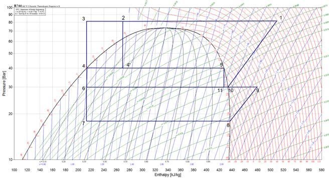
Page 4 of 54
A Appendix A Financing .....................................................................................................................................43
A.1 EU and partner countries .....................................................................................................43
A.2 Germany ..................................................................................................................................44
A.2.1 Call for project grants and financial support ......................................................44
A.2.2 Soft loans ..................................................................................................................45
A.3 Norway ....................................................................................................................................47
A.3.1 Call for project grants and financial support ......................................................47
A.3.2 Tax incentives .......................................................................................................... 48
A.4 Spain ....................................................................................................................................... 49
A.4.1 Call for project grants and financial support ..................................................... 49
A.4.2 Soft loans ................................................................................................................. 50
A.4.3 Tax incentives ........................................................................................................... 51
A.4.4 Financing by means of energy service companies ........................................... 52
A.5 Macedonia ..............................................................................................................................53
A.5.1 Call for project grants and financial support ......................................................53
A.5.2 Soft loans ..................................................................................................................53
Table of Figures
Page
Figure 1 Air curtain principle. ........................................................................................................................... 11
Figure 2 Example of how different climatic zones can be achieved within a grocery store. ............... 11
Figure 3 (a) 1st, (b) 2nd and (c) 3rd generation central CO2 refrigeration systems for supermarkets. .... 14
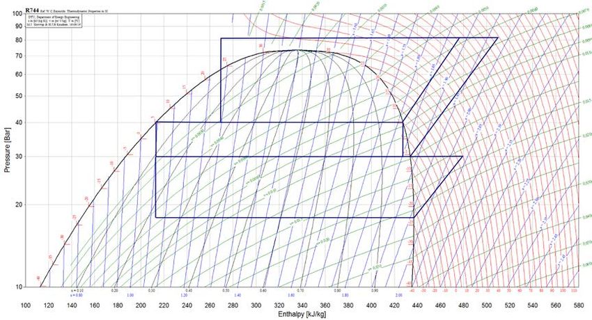
Figure 4 (a) CO2 booster system with mechanical subcooling and (b) log(p)-h diagram for CO2
booster system with (3-4) or without (2-4') mechanical subcooling. ....................................... 14
Figure 5 Log(p)-h diagram for 2nd generation CO2 system; booster system with parallel
compression. ...................................................................................................................................... 15
Figure 6 (a) Principle scheme for supermarket refrigeration system with ejector and (b) the
corresponding log(p)-h diagram. .................................................................................................... 17
Figure 7 Approximate cooling load for an open refrigerated multi-deck cabinet (Kauffeld 2015). ... 20
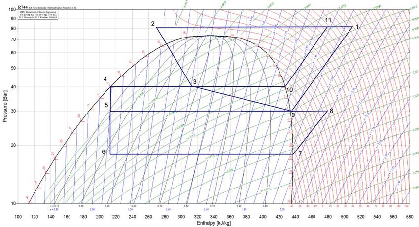
Figure 8 Supermarket AHU unit by Systemair, employed in REMA 1000 Kroppanmarka in
Trondheim. Here the venting (free air cooling mode) is shown (Hafner 2013)........................ 21
Figure 9 Local direct CO2 heating/cooling unit by Enex (Girotto 2016). ................................................ 24
Figure 10 Integrated refrigeration and HVAC solution for REMA 1000 Kroppanmarka
supermarket, Trondheim, with CO2 as the refrigerant (Hafner 2013). ..................................... 25
Figure 11 CO2 gas cooler heat recovery in a cold climate (with high external heating demand),
shown in a temperature-entropy (T-s) diagram.......................................................................... 26
Figure 12 CO2 gas cooler heat recovery in a hot climate, shown in a temperature-entropy (T-s)
diagram............................................................................................................................................... 26
Figure 13 Energy saving in percentage of aggregated energy consumption of the refrigeration
system through different measures (redrawn from (Kauffeld 2015)). ..................................... 36
Table of Tables
Page
Table 2.1 Exemplar values for normative heat transfer coefficients for walls, roof and floor
according to the building regulations in different parts of Europe. .......................................... 9
Table 2.2 Exemplar values for normative heat transfer coefficients for windows and doors. .............. 10
Table 3.1 Temperature levels for refrigeration and AC in a supermarket. ................................................ 13
Table 3.2 Summary of different thermal storage options suitable for supermarkets. .......................... 22
The research leading to these results has received funding from the
European Union/EASME H2020 Programme under Grant Agreement No 696076.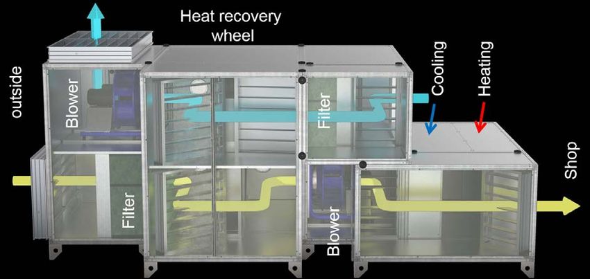
Page 5 of 54

EXECUTIVE SUMMARY
This report serves as a starting point material for training supermarket stakeholders in building new, eco-
friendly supermarkets. The report covers building design, refrigeration, heating, ventilation and air
conditioning (HVAC), as well as lighting, with the main focus being on the refrigeration and HVAC system.
New, innovative and promising technologies and solutions are introduced, accompanied with case
examples from different parts of Europe.

For the refrigeration system, the focus is on CO2-only systems, as this is regarded as the most energy
efficient and eco-friendly approach. State of the art CO2 system layouts using ejectors for expansion work
recovery, suitable for both warm and cold climates, are presented. An integrated system solution covering
both the refrigeration and HVAC, allowing optimal heat recovery, is highly recommended, and a possible
system layout for such an integrated approach is presented.

A prerequisite for energy efficient refrigeration are good components, including compressors, evaporators,
condensers, and expansion devices, as well as a good cabinet design. Flooded direct expansion
evaporators, enabled through the use of ejectors, are highly recommended. Such evaporators allow
increased evaporation temperatures due to the improved heat transfer, and consequently also reduced
demand for defrosting cycles, leading to a significantly higher overall system COP. Regarding cabinet
design, having glass doors and lids is a crucial first step, allowing energy savings of 40 % or more. A detailed
list of the design aspects leading to optimal cabinet energy efficiency is provided in the report.

Thermal energy storage is an important part of an energy efficient supermarket refrigeration system,
allowing reduction in the peak cooling demand and thereby in the installed refrigeration capacity. Different
thermal storage options suitable for supermarkets include energy wells as a seasonal storage, and hot
water storage tanks and phase change materials (PCM) as a short-term thermal storage. The report
presents an overview of these technologies, and how they can be or have been applied in supermarkets.

For lighting in supermarkets, LED lights both in- and outside the store, as well as inside the cabinets, should
be used owing to the low electricity demand and low heat production. LEDs have the additional advantage
that they consume less energy the cooler they are kept, opposite to fluorescent tubes. LED lights together
with adapted utilization of daylight and intelligent control with respect to traffic and amount of daylight
available can thus enable significant energy savings.

The most crucial measures for improving the supermarket energy efficiency are summarized as golden
rules at the end of the report.

Apart from the technical aspects, the report discusses the non-technical barriers for the uptake of new
eco-friendly supermarkets, as well as possible solutions to overcome these barriers. Increased investment
costs are often regarded as the biggest non-technical barrier, and financing opportunities to overcome this
barrier are therefore included for different European countries.

                              The research leading to these results has received funding from the
                         European Union/EASME H2020 Programme under Grant Agreement No 696076.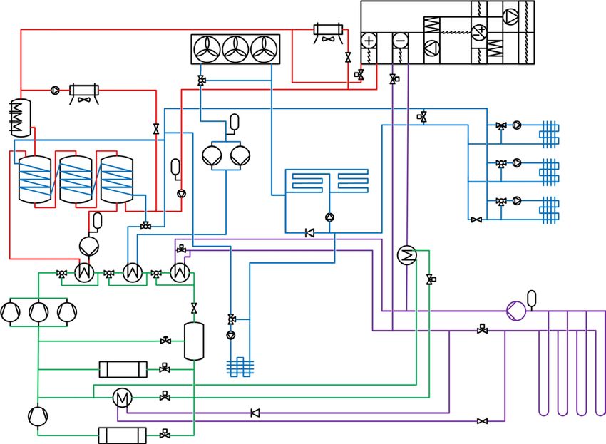
Page 7 of 54

1        INTRODUCTION
Efficient solutions for supermarket heating, cooling and refrigeration - such as integrated systems or the
use of natural refrigerant-based equipment - are already available in the European market. However, their
use is not yet widespread due to remaining non-technological barriers, including lack of knowledge and
awareness, social, organizational and political barriers.

The European project SuperSmart aims at removing these barriers and additionally supports the
introduction of the EU Ecolabel for food retail stores. The EU Ecolabel can encourage supermarket
stakeholders to implement environmentally friendly and energy efficient technologies and thus reduce the
environmental impact of food retail stores.

Within the project several activities are carried out to remove the barriers: campaigns to raise the general
awareness and spread the information about energy efficient and eco-friendly supermarkets, as well as
training activities within the following specific topics:
    1. Eco-friendly supermarkets – an overview
    2. How to build a new eco-friendly supermarket
    3. How to refurbish a supermarket
    4. Computational tools for supermarket planning
    5. Eco friendly operation and maintenance of supermarkets
    6. EU Ecolabel for food retail stores

For each of the topics a set of training material is developed, which will be used in the training activities.
The different kinds of training activities are:
    1. Conference related activities
    2. Dedicated training sessions
    3. Self-learning online activities

Dedicated training sessions are free-of-charge for the different stakeholders in the supermarket sector.
This means that highly-qualified experts from the project consortium will carry out a training session on a
specific topic at the premises of the stakeholder. If you are interested in receiving such a training regarding
any of the above mentioned topics, please contact the project partner via the project website:
www.supersmart-supermarket.info.

The present report forms a part of the training material for topic How to build a new eco-friendly
supermarket. It can be used for self-studying and is freely available. There will be conferences, where this
topic is included as a training activity. Information on conferences where members of the SuperSmart-
team will be present as well as the planned training activities can be found on the project website.

1.1      Introduction to How to build a new eco-friendly supermarket
New supermarkets are being built all the time. In the UK alone, supermarket chains are planning to open
enough new stores in the years ahead to cover 500 football pitches (Neate 2011). At the same time,
supermarkets consume huge amounts of energy. The annual energy use in supermarkets in for instance
Germany is estimated to be 16 TWh, in Spain 6.8 TWh, in Italy 8.2 TWh, and in Norway about 1.5 TWh (Grocery
Universe 2013). Moreover, supermarkets contribute to climate gas emissions both directly through leakage
from the refrigeration system, as well as indirectly due to the energy consumption. Overall the cold chain
is believed to be responsible for approximately 2.4 % of global greenhouse gas emissions (Foster and Evans
2015). The highest proportion – or all when natural refrigerants are used – of the climate gas emissions
comes from emissions related to energy consumption (Kauffeld 2015). It is hence of utmost importance
that new supermarkets should be built to be energy efficient, and based on utilization of natural
refrigerants, primarily CO2, i.e. refrigerant R744.

Nevertheless, many new energy efficient technologies for retail refrigeration based on CO2 are not yet fully
mature, and supermarket stakeholders are sceptical towards the commissioning of these technologies, in
particular in warmer climates. In order to increase the confidence and thereby accelerate the uptake of
new eco-friendly solutions, training campaigns dedicated to the supermarket stakeholders are urgently
needed.

                              The research leading to these results has received funding from the
                         European Union/EASME H2020 Programme under Grant Agreement No 696076.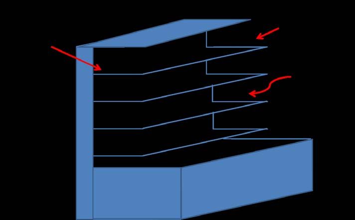
Page 8 of 54

The choice of the refrigeration and HVAC system to be installed in a new supermarket lies primarily in the
hands of the supermarket chain and the shop owners, as well as in the hands of consultants and engineers
designing the system. Hence these stakeholders need to be addressed, to raise their knowledge on existing
eco-friendly technologies and their potential for reducing operational costs and total cost of ownership, as
well as to inform about the different financing opportunities to cope with the increased initial costs.
Furthermore, knowledge on CO2 systems is required from the installers and technicians, in particular the
refrigeration engineers and plumbers. To ensure correct dimensioning and successful, energy efficient
operation of the refrigeration system, it is crucial to reach these stakeholders.

The objectives of this report are:
    •  To discuss optimal building design for supermarkets
    •  To present the state of the art and promising future technology for energy efficient and eco-
       friendly supermarket refrigeration and HVAC, including heat recovery and thermal storage and
       considering different climatic conditions
    •  To discuss the non-technological barriers and possible solutions for building new energy efficient
       supermarkets
    •  To present case examples of supermarkets with outstanding energy solutions from different parts
       of Europe

In addition, financing options for building new, energy efficient supermarket are given in appendix A for
different European countries, including EU and partner countries, and more specifically Germany, Norway,
Spain and Macedonia.

A supermarket is a complex energy system, having to satisfy chilling and freezing of valuable food at
different temperature levels, and at the same time maintaining customer comfort in the sales area. The
measures that can be taken to reduce the energy use are various, starting from an optimal building design,
to correct dimensioning and operation of the refrigeration system and all its components. This chapter
discusses the technical framework for building a new, energy efficient supermarket, starting with the
building design and requirements in different parts of Europe, subsequently discussing the refrigeration
and HVAC system, focusing on solutions based on CO2 as the cooling medium, which is considered as the
most eco-friendly and energy efficient solution. Other trends using natural refrigerants are discussed given
in the SuperSmart project report D2.2, Eco-friendly supermarkets – an overview (Karampour, Sawalha et al.
2016). Finally, lighting and electrical equipment, as well as possibilities for local power generation in a
supermarket will be discussed.

                             The research leading to these results has received funding from the
                        European Union/EASME H2020 Programme under Grant Agreement No 696076.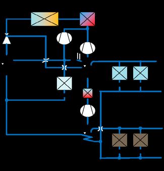
Page 9 of 54

2           BUILDING DESIGN

2.1         Size, shape and outer design
The size and shape of a supermarket is critical for highest possible energy efficiency, and regarding the
customer experience. To minimize the heat losses or gains, the building should be as compact as practically
possible. Regarding the size; a too high ceiling increases both the construction costs as well as the
operation costs due to increased heating and cooling demand, while a too low ceiling creates a
claustrophobic effect. The height should hence be designed for the minimum practical limit. The same
applies for floor space, which should be designed based on the amount of traffic corresponding to 90 % of
the busiest day (EPA 2010). Aisle widths should be varied based on traffic density.

Generally, the sunlight is a big heat load for the stores. In some countries this is a rare problem, but still
creates high peak loads a few days a year. For a stand-alone store, sun shading is a simple but important
measure to reduce this load. Reflecting walls (white or mirror) could also reduce the load. For supermarkets
that are a part of a building complex, the placement of the store should be below or on the ground level,
preventing the sun from reaching down to it. This is usually the case, and such stores have generally lower
cooling loads than stand-alone stores. Having the supermarket as a part of a building complex is
advantageous also in the sense that the condenser heat can be utilized to cover the heating demand in the
other parts of the complex.

2.2         The building envelope
The building envelope – including walls, floor, roof, windows and doors – defines the heating and cooling
demand of the building with respect to the ambient climate. It should be designed such that the heat load
in the hot periods is minimized, and that a pleasant indoor climate is maintained in the colder periods. This
section discusses suitable building materials for supermarkets and the prevailing requirements for the
building envelope in the different parts of Europe. Novel ideas for increased energy efficiency for instance
regarding fenestration and doors are included.

2.2.1       Floor, walls and roof

Proper insulation is crucial to reduce heat losses from the supermarkets in cold climates in the winter time,
as well as to reduce overheating of the building in the summertime. A trade-off between space costs and
investment costs for insulation of walls must be made, as the more space efficient insulation is, the more
expensive it is as well. Exemplar values for normative heat transfer coefficients according to the newest
building standards in the different parts of Europe are given in Table 2.1. It has to be pointed out that many
of the values are aimed for commercial buildings in general, not particularly for supermarkets.
Table 2.1      Exemplar values for normative heat transfer coefficients for walls, roof and floor according to
               the building regulations in different parts of Europe.

                                                                  Heat transfer coefficient [W/m²K]
                                                        Walls                    Roof                     Floor
 Norway       (passive  house/low-energy                                  0.08-0.09/0.10-
                                                 0.10-0.12/0.15-0.16                                 0.08/0.10-0.12
 building) (Standard Norge 2012)                                               0.12
 Sweden (for buildings with electric
 heating/heating method other than                    0.10/0.18               0.08/0.13                 0.10/0.15
 electric heating) (Boverket 2015)
 Germany (for building projects from 2016
 (EnEV 2014) / passive house criteria,
                                                  0.28 / 0.09-0.50        0.28 / 0.09-0.50           0.28 / 0.09-0.50
 depending     on     the    climatic zone
 (Passivhaus Institut 2015))
                                                                                                 0.55-1.35/0.35-1.2 (in
 Spain (the value depends on the climatic
                                                      0.55-1.35               0.35-1.20              contact with
 zone) (BOE 2013)
                                                                                                     ground/air)
 Macedonia                                               0.35                     0.2                      0.4

                               The research leading to these results has received funding from the
                          European Union/EASME H2020 Programme under Grant Agreement No 696076.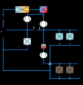
Page 10 of 54
For the construction, materials with low CO2 emissions throughout the life cycle should be chosen as far as
possible, depending on the level of the environmental ambitions. As an example, a new, highly eco-friendly
Kiwi-supermarket in Elverum, Norway, used near-produced wood as the main building material (KIWI 2016).
Apart from the low environmental impact, it was pointed out that wooden wall constructions contribute to
a good indoor climate and a reduced demand for ventilation.
2.2.2 Windows and doors
To reduce the cooling demand during warm periods, the thermal load from the sun through windows
should be minimized. Therefore the window area in supermarket is generally low. The most energy efficient
approach would be to have no windows at all, however a supermarket without any windows is not a very
pleasant one. At the same time utilization of natural light should be maximized in order to reduce the
electricity demand for lighting.
At REMA 1000 Kroppanmarka in Trondheim, Norway, this was accomplished such that parts of the north
and west-facing walls as well as a small part of the roof were covered with translucent daylight panels, so-
called Nordic Daylight Panels (Aerogel Norge 2016). These panels are filled with highly insulating porous
silica aerogel (heat transfer coefficient 0.59 W/m²K), and spread the light diffusively into the room,
preventing the creation of hot spots. The panels have a light transmission of 45 %. Daylight panels are
employed also in a Kiwi-supermarket in Auli, Norway (KIWI 2015).
Table 2.2 Exemplar values for normative heat transfer coefficients for windows and doors.
Heat transfer coefficient [W/m²K]
Norway (passive house/low-energy building) (Standard Norge 2012) ≤0.80 / ≤1.2
Sweden (for buildings with electric heating/heating method other than
1.1/1.3
electric heating) (Boverket 2015)
Germany (for building projects from 2016 (EnEV 2014) / passive house criteria,
1.5 / 0.45-1.40
depending on the climatic zone (Passivhaus Institut 2015))
Spain (BOE 2013) 2.5-5.7
Macedonia 1.7
Infiltration through doors can be reduced by using double doors, i.e. having a vestibule (an entrance area)
between the outer and the interior door. Adding a vestibule can provide energy savings of up to 6 % in
warm climates (NREL 2012). The infiltration can be further reduced by operational changes (when and how
long the doors are open) and changes in the effective door area. These measures may be applied to
customer doors, or to shipping and receiving doors used by retailers and their product distributors.
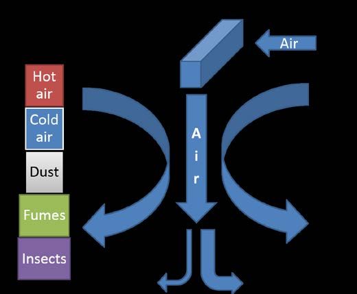
Another energy efficiency measure for entrance doors is using an air curtain, i.e., a controlled stream of air
across the opening (Figure 1). An air curtain provides energy savings by limiting the transfer of air between
indoors and outdoors, and limits also the flow of insects, dust and humidity to the supermarket (Berner
International 2014). It is however important that the air curtain is a part of the integrated refrigeration and
HVAC system, hence utilizing excess heat from the refrigeration system. An air curtain utilizing electric
heaters during winter time will have a negative impact on the total energy efficiency of the supermarket.
The research leading to these results has received funding from the
European Union/EASME H2020 Programme under Grant Agreement No 696076.Page 11 of 54
Figure 1 Air curtain principle.
2.3 Floor plan and interior design
To minimize thermal losses, the distribution of hot and cold zones within a store matters. Generally,
products that are sold hot should be placed far away from the refrigerated products. Products that can be
stored at normal room temperatures, but still not too high temperatures (fruit and vegetables) could be
placed close to the cold room, so that the cold leakage is utilized. In this way, a temperature gradient,
beneficial for the products and energy use is achieved.
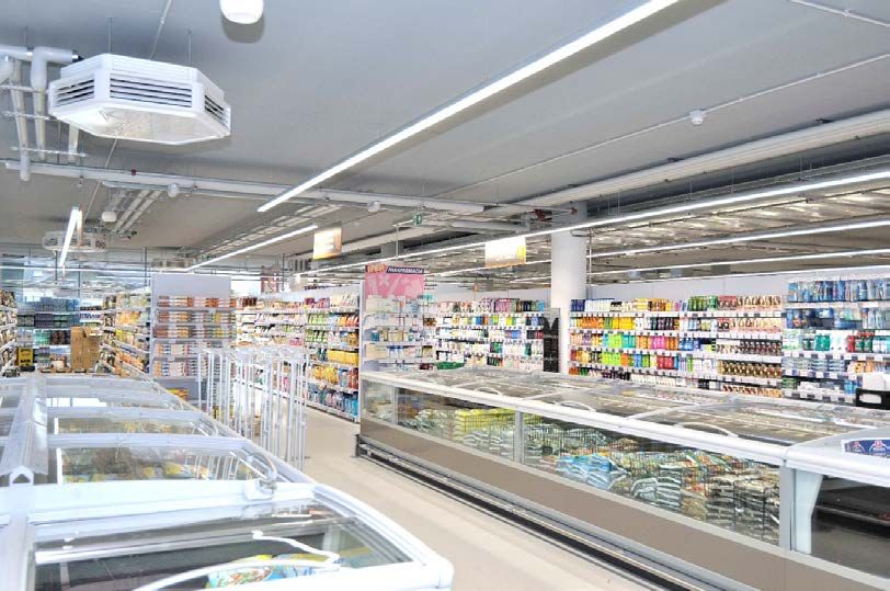
An example of how climatic zones for lower heat losses can be arranged in a shop is shown in Figure 2. In
this figure, the orange zone contains heated products and holds a generally high temperature all year,
whereas there is an own room for chilled products displayed in cold cabinets in the light blue room. It is a
good practice to have a cold storage room and space for inserting more products into the cold shelves from
the backside of the cabinets for products with highest turnover rate, such as dairy products. Fruit and
vegetables are placed in front of the cold disks, hence being cooled down by the cold air leaking from the
disks. The shelves between the hot and cold zones will have an intermediate temperature. The entrance
and payment area will be influenced, but not controlled, by the outdoor temperature.
Figure 2 Example of how different climatic zones can be achieved within a grocery store.
The research leading to these results has received funding from the
European Union/EASME H2020 Programme under Grant Agreement No 696076.Page 12 of 54
2.4 Lighting and electrical equipment
Lighting corresponds to approximately 20 % of the supermarket energy demand, hence an energy efficient
lighting is crucial for an eco-friendly supermarket. At the same time, optimal lighting is important
considering the sales: correct lighting for the different products will bring out the best of the products, and
correct ambience will make the customers feel at ease (Philips Electronics 2012). LED-lights are the
preferred type of lighting owing to the low electricity demand and low heat production, and the colour of
LED lights can be optimized with respect to the different sales areas (Philips Electronics 2012).
Lighting energy consumption can be further reduced by using clever lighting control. This may include
using less lights when enough daylight is available and using presence detection features to balance light
levels according to the volume of store traffic. An automatic lighting control system which switches off the
ceiling lights when sufficient daylight is available is employed for instance at the REMA 1000 supermarket
at Kroppanmarka in Trondheim (Hafner and Tønseth 2014) and at KIWI Fjeldset in Elverum, Norway (KIWI
2016). Furthermore, room surfaces painted with matt colours with high reflectance should be used. Energy
efficiency in lighting is further discussed in report D2.4. How to refurbish a supermarket CIRCE, 2016).
2.5 Local power generation
Supermarkets have a high specific power demand, which peaks in the summertime when the cooling load
is the highest, and additionally usually a large roof area. This renders supermarkets suitable for local power
production with solar PV, and this is already practiced in several supermarkets in Europe and Asia (Grovew
2014, Richardson 2015), including Northern countries such as Norway (KIWI 2015). Local power generation
with renewable energy systems is discussed in more detail in the report D2.4, How to refurbish a
supermarket (Mainar Toledo and García Peraire 2016).
Sun, or wind, are however not the only options for local power generation. Sainsbury’s Cannock store in the
UK will be powered using electricity generated using food waste from Sainsbury’s stores across the UK (J
Sainsbury 2014). The principle is to send zero operational waste to landfill. Any food waste that is unsuitable
for charitable donations or animal feed is sent to anaerobic digestion and turned into bio-methane gas,
which is then used to generate electricity. Sainsbury’s is already the UK’s largest retail user of anaerobic
digestion, generating enough energy to power 2 500 homes each year.
The research leading to these results has received funding from the
European Union/EASME H2020 Programme under Grant Agreement No 696076.Page 13 of 54
3 REFRIGERATION AND HVAC
There are two principal temperature levels in supermarkets: medium temperature (MT) for preservation of
chilled food and low temperature (LT) for frozen products. In an integrated solution, the refrigeration
system is also responsible for air conditioning (AC) of the store. The desired temperature levels for MT, LT
and AC, as well as typical and ideal evaporation temperatures are given in Table 3.1. The measures for
achieving higher evaporation temperatures for LT and MT are discussed in section 3.4.3. For AC, a typical
evaporation temperature is +3 °C to provide chilled water at +7 °C. This is still a very low temperature to
maintain an indoor temperature of 20 °C, owing to indirect system solutions used. In long-term one should
aim for direct systems, allowing higher AC evaporation temperatures (see section 3.7).
Table 3.1 Temperature levels for refrigeration and AC in a supermarket.
Desired temperature level [°C] Typical evaporation Ideal/achievable evaporation
temperature [°C] temperature [°C]
Chilled food 1 to 14 –10 to -5 -2
Frozen food -12 to -18 or lower –35 to -30 -25
AC ~20 ~3 12
Three main types of refrigeration systems are used in stores: stand-alone equipment, condensing units and
centralised systems (UNEP 2002). A detailed explanation of these systems is given in the SuperSmart
project report D2.2, Eco-friendly supermarkets – an overview (Karampour, Sawalha et al. 2016). For
centralised system, there are two main types: direct (direct expansion, DX) and indirect system, also
explained in the project report D2.2.
Indirect systems permit a lower refrigerant charge, and enables the use of flammable or toxic refrigerants
when the refrigeration unit is located in a machinery room separated from the sales area. Indirect systems
were hence previously recommended, in particular for hypermarkets where the distances are long.
However, CO2 has excellent transport properties – very low friction losses and low temperature drop per
pressure drop – rendering direct systems with CO2 feasible also for large supermarkets (R744.com 2015a).
Direct systems offer better energy efficiency and more stable temperature levels in the refrigerated
cabinets, and are additionally less complex to operate than indirect systems.
Ideally, most or all of the refrigeration demand should be covered by an integrated, central refrigeration
system taking care of chilling and freezing the food stuff as well as AC, condenser heat being recovered for
different heating purposes. The primary focus in this chapter is hence on the central refrigeration system,
and direct systems, with CO2 as the refrigerant of choice, covered in section 3.1. Refrigeration components,
optimal cabinet design, air-handling unit, thermal storage and distribution of heat and cold in the
supermarkets are discussed in sections 3.4-3.7. An example of an integrated system layout and strategies
for optimal heat recovery are presented in section 3.8.
3.1 Central refrigeration system
For the central refrigeration system, a direct system based on CO2 as the working fluid has become the
preferred solution for European retailers. The first installation was made in 2004 by Linde, and by 2013 there
were nearly 3000 installations in Europe (Shecco 2013). Figure 3 presents simplified system layouts for 1st,
2nd and 3rd generation CO2 refrigeration systems. The pros and cons of these systems, and their suitability
to different climates, is discussed in more detail below.
All figures in this section are highly simplified to clarify the principles. In reality, a number of compressors
might be placed in parallel to match the varying capacity requirements, and in the same way one could
include several evaporators and heaters. Missing in the figures is also the internal heat exchanger (IHX)
between the point after the gas cooler and just before the LT compressor, which both ensures dry
compression and provides subcooling, hence improving the process efficiency.
3.1.1 1st generation: The booster system
The 1st generation, i.e. the booster system (Figure 3 (a)), is the most widely applied solution. The system fits
best to cold climates, where the demand for AC is low. In this system, the LT cabinets/evaporators are
served by a separate, smaller booster compressor – hence the name booster system – which lifts the
The research leading to these results has received funding from the
European Union/EASME H2020 Programme under Grant Agreement No 696076.Page 14 of 54
pressure to the medium temperature level. The discharge gas from the booster is then merged with the
gas coming from MT evaporators. As the outlet temperature from the LT compressor is generally high, up
to 90 °C, de-superheating recommended before mixing of the fluids. Heat from the de-superheater may
also be utilized to different purposes, such as production of domestic hot water (DHW).
(a) (b) (c)
Figure 3 (a) 1st, (b) 2nd and (c) 3rd generation central CO2 refrigeration systems for supermarkets.
After the gas cooler, CO2 is throttled by the high-pressure control valve to the intermediate pressure
receiver (separator). Liquid from this receiver is throttled further to either to LT or MT level, whereas flash
gas is taken to the MT compressor through a flash gas by-pass valve (FGBV). The FGBV is crucial in
controlling the pressure level in the separator, which enables a safe supply of liquid refrigerant to all
evaporators.
The general booster system will have a slightly reduced energy efficiency in warm climates, where the gas
cooler output temperature is high, due to higher expansion losses and increased heat rejection losses. A
possible solution to this problem is using a mechanical subcooler, which cools down the CO2 leaving the
gas cooler, leading to reduction in the vapour fraction at the liquid receiver inlet, and consequently to a
performance improvement (Hafner, Hemmingsen et al. 2014). Figure 4 shows the system layout with
mechanical subcooling, as well as the log(p)-h diagram for the cycles with and without mechanical
subcooling. A subcooling system will however increase the investments costs, and these systems have had
reliability issues related to the subcooler heat exchanger as well. Alternatives for a subcooling unit are for
instance an additional gas cooler with evaporative/wet cooling, or heat rejection to an energy well,
providing a temperature level below ambient temperature during the warm season.
Figure 4 (a) CO2 booster system with mechanical subcooling and (b) log(p)-h diagram for CO2 booster
system with (3-4) or without (2-4') mechanical subcooling.
On the other hand, too low gas cooler outlet temperatures are a challenge in cold climates during winter
time. If the temperature at the inlet of the high-pressure control valve reduces below 5 °C, the pressure
level in the separator drops below the level which is required to deliver liquid refrigerant to all the
The research leading to these results has received funding from the
European Union/EASME H2020 Programme under Grant Agreement No 696076.Page 15 of 54
evaporators. This problem can be prevented with bypassing, or letting only a small portion of the working
fluid through the external gas coolers and using only heat recovery (see Figure 6 (a)). Alternatively, a
separate, significantly smaller gas cooler, dimensioned for winter conditions, may be used.
3.1.2 2nd generation: Booster system with parallel compression
The amount of vapour downstream of the high-pressure control valve increases as the external
temperature rises. The reduced specific cooling capacity leads to an increment in the amount of refrigerant
which has to be compressed from medium to high pressure, implying a growth in the energy consumption
associated with the MT compressors, especially during summertime (Gullo, Elmegaard et al. 2016). A
solution to this challenge is to adopt an auxiliary, parallel compressor on the purpose of sucking either a
part or the entire amount of vapour from the separator and compress is directly to the gas cooler pressure.
Such a system solution is called booster system with parallel compression, shown in Figure 3 (b). The
corresponding log(p)-h diagram is shown in Figure 5.
Having an auxiliary compressor reduces the losses due to flashing. The auxiliary compressor is only
operative if there is a sufficiently large amount of flash gas (otherwise the compressor would have a too
poor operation). If the amount of flash gas is low, e.g. during winter time, it is throttled via the flash gas by-
pass valve as in a standard booster system.
Furthermore, energy efficient integration of AC is possible with parallel compression. The AC evaporator
outlet enters directly the separator (see the following section). In this case the AC cooling capacity is
provided by the auxiliary compressor, determining the pressure level of the separator.
Figure 5 Log(p)-h diagram for 2nd generation CO2 system; booster system with parallel compression.
3.1.3 3rd generation: The ejector system
The state of the art technology is to replace the high-pressure control valve with ejectors enabling for
expansion work recovery, as illustrated in Figure 3 (c) and in more detail in Figure 6 (a). This is particularly
important for CO2 systems to be operated in warm climates, in which case the expansion losses are high,
however, this ejector configuration can also be applied in cold climate locations. What an ejector does is
that it entrains partly the low-pressure fluid downstream of the MT evaporators by means of high—pressure
fluid coming from the gas cooler, accelerated in the motive nozzle of the ejector (Hafner, Försterling et al.
2014). Kinetic energy is converted into static energy, i.e. the pressure level between the suction nozzle and
ejector discharge is equal to the pressure difference between the MT evaporators and the separator. The
amount of vapour pre-compressed by the ejectors and discharged into the separator is determined by the
available expansion work. The ejectors extend the operation time of the parallel compressors, by increasing
the amount of vapour to be compressed. Ejectors hence shift a part of the MT compressor load to the
The research leading to these results has received funding from the
European Union/EASME H2020 Programme under Grant Agreement No 696076.Page 16 of 54
parallel compressor which has to overcome a significantly lower pressure lift, hence reducing the total
power demand.
When ejectors are used, some of the liquid from the low-pressure receiver is fed to liquid ejectors and
vapour to vapour ejectors. The operation principle is as described above for both ejectors, but the
dimensions of the internal flow channels are different. For active control of the discharge pressure at
varying ambient (heat reclaim) conditions, a multi-ejector solution is necessary, where a number of ejectors
are connected in parallel. To maintain a certain high side pressure, the requested effective flow area of the
ejector rack is then varied through on-off operation of the individual ejectors. Other vendors have
developed large variable capacity ejectors, in which case only one ejector is used to control the high side
pressure by varying the effective flow area through flow restriction in the nozzle (R744.com 2016).
Moreover, using ejectors enables to operate the evaporators without any superheat, i.e. in flooded mode.
In standard DX evaporators, part of the evaporator has to provide superheating of the refrigerant, reducing
the heat transfer rate. In flooded direct expansion evaporators, the vapour fraction of the refrigerant
downstream of the MT evaporators can be continuously kept at around 100 %. This leads to increased heat
transfer rate and better utilization of heat exchanger area, allowing significantly higher evaporation
temperatures (around -2 °C with optimal design of the display cabinets) and hence increased overall energy
efficiency for the system.
Figure 6 (a) presents also an innovative approach for integrating AC capacity in the circuit, without a
separate AC compressor. The AC loop is cooled down by evaporating CO2 in natural circulation from the
separator, and is activated with an on/off valve. The evaporated CO2 is returned to the upper part of the
separator, from where also the parallel compressors get their suction flow. With this approach, control and
regulation becomes easier as there are only two evaporation pressure levels. The pressure level in the
receiver (around 40 bar, corresponding to an evaporations temperature of ca. 5 °C) is low enough to allow
sufficient cooling for the AC loop. The system costs are lower as no extra compressor, condenser, control,
etc. is required for AC.
Depending on the design of the HVAC unit, direct expansion of CO2 in the ventilation air stream could be
applied to further reduce the total installation cost, avoiding the entire chilled water loop. This would
additionally enable a further raise in the separator pressure level, since the required evaporation
temperature for direct air cooling is in the range of +10 °C (corresponds to ~45 bar separator pressure).
The research leading to these results has received funding from the
European Union/EASME H2020 Programme under Grant Agreement No 696076.Page 17 of 54
(a)
(b)
Figure 6 (a) Principle scheme for supermarket refrigeration system with ejector and (b) the
corresponding log(p)-h diagram.
3.2 Condensing units
The typical refrigeration capacity of a condensing unit is in the range of 1 to 20 kW. Several display cabinets
and/or indoor AC units can be connected to these units, which explains their global popularity for small
shops and convenience stores. Currently H(C)FC refrigerants are dominating this market segment,
supported by Asian manufacturers. There are however no technical barriers which would prevent CO2
refrigeration units from becoming an alternative working fluid for condensing units. In Japan, more than
The research leading to these results has received funding from the
European Union/EASME H2020 Programme under Grant Agreement No 696076.Page 18 of 54
1000 small supermarkets have been successfully converted from HFCs to CO2 during the past years, as
described by Uto (2016). Energy savings up to 27 % are reported by the end-users.
A successful transfer of this technology from Japan to Indonesia has also taken place (Santoso 2016, Uto
2016). 12 pilot stores in Indonesia are equipped with the same CO2 technology as in Japan. Despite being
located close to the equator, energy savings of around 20 % as compared to conventional HFC systems
used previously and additionally a 15 % higher turnover due to increased customer comfort have been
reported for the stores in Indonesia (Santoso 2016).
All these new Asian CO2 units are integrated systems, i.e. the AC unit (and space/hot water heating where
needed) is a part of the refrigeration unit. The systems are operated without ejector technology, hence
their energy efficiency could still be improved. Nevertheless, in the South East Asian countries the
investment costs for the new CO2 units are still relatively high as compared to traditional H(C)FC units,
which hinders large-scale commissioning of the technology.
3.3 Plug-in units
Plug-in units have the advantage of having a relatively small refrigerant charge and very leak tight circuits,
since the refrigeration system is finished when the product leaves the factory. They are a tempting option,
as the specific investment costs are extremely low as compared to a central refrigeration system, and they
are also cheap and easy to replace upon failure. The main disadvantage is that the condenser heat is
released directly to the sales area, creating an additional heat load to the supermarket and hence increasing
the energy costs (AC requirement). Moreover, still non-natural refrigerants are often utilized, even if more
energy efficient options with natural working fluids are available. In general, in larger stores, having a
centralised refrigeration unit, plug-in units should be avoided as far as possible. If still some plug-in units
have to be installed, those utilizing natural refrigerants (hydrocarbons), available from most suppliers,
should be chosen.
Plug-ins utilizing CO2 are also available from ISA (ISA 2016) and SANDEN/Hauser (R744.com 2015b). In tests
by ISA comparing plug-in units utilizing R404A, propane and CO2, 14 % lower energy consumption was
obtained with the propane unit and 16 % reduced energy usage was measured with the CO2 unit as
compared to the R404A unit (Menghini 2016). The initial system cost was however 8 % higher for both the
propane and CO2 unit as compared to the R404A unit, owing to the double compressor in the case of the
propane unit and heat exchanger costs in the case of the CO2 unit. SANDEN reports 21 % reduced energy
use and 15 % higher initial costs when comparing CO2 plug-in unit with an HFC unit (Gillaux 2016).
3.4 Refrigeration components: design and operation
3.4.1 Compressors
Frequency control/variable speed drive compressors enable to adjust the cooling performance of the
refrigeration system to the demand. This has earlier been done by on/off control of individual compressors
owing to high costs of frequency converters; however the prices are lower now. Frequency control may
allow energy savings of up to 25 %, improved performance at part load and increased working life
(Bouchareb, Gibson et al. 2003), as well as a reduction in the total number of installed compressors.
For CO2 compressors, many different suppliers, and all capacity ranges (from small stores to hypermarket
scale) are nowadays available. Reciprocating compressors are the dominating technology, due to the
strongly varying heat rejection conditions (condensing pressure). A reciprocating compressor is able to
adapt to the varying conditions better, with less variation in efficiency, than other compressor designs. For
LT, the pressure ratio is however more constant (between LT and MT) and other compressor types may be
applied as well.
3.4.2 Expansion device
Use of electronic expansion valves instead of thermostatic expansion valves allows an adaptive adjustment
of the control characteristics during operation. Electronic expansion valves are also able to operate with a
lower pressure difference, allowing a more radical decrease in condensation temperature. In a large Italian
supermarket, energy savings of between 20 % (summer) and 35 % (winter) were achieved by using
The research leading to these results has received funding from the
European Union/EASME H2020 Programme under Grant Agreement No 696076.Page 19 of 54
electronic expansion valves for the MT and LT evaporators, as compared with a similar supermarket using
thermostatic expansion valves (Bobbo, Camporese et al. 2005). For future CO2 refrigeration systems, the
individual local expansion valves of the cooling and freezing equipment attached to the centralised unit
should also be able to handle flooded operation.
3.4.3 Evaporators/condensers
An evaporation temperature increase by 3 K reduces the energy use by approximately 3 %. Lowered
evaporation temperature can be achieved by increased evaporator area, and by using an IHX installed after
the evaporator. An IHX allows transferring superheat, only required to safeguard the compressors, into the
refrigerant leaving the evaporator from the refrigerant leaving the gas cooler, which is then simultaneously
subcooled. This increases the overall energy efficiency.
Increased evaporation temperature is also facilitated by using flooded direct expansion evaporators,
enabled through the use of ejectors, as was discussed in section 3.1.3. For flooded evaporators, the
evaporation temperature should ideally be -2 °C for MT chillers and -25 °C for LT freezers. These
temperature levels are the highest that can be achieved today in pilot supermarkets.
As the energy use of the compressor is dependent on the lowest evaporation temperature, it is of utmost
importance that all cabinets connected to the same compressor are designed for the same evaporation
temperature.
Evaporators are often defrosted by means of a time shift, even if defrosting is often not necessary at the
time pre-set by the timer. In new CO2 refrigeration systems using flooded evaporators with elevated
evaporation temperatures, defrosting once a week is sufficient! Alternatively, defrost on demand can be
performed by observing the evaporation temperature (the evaporator temperature drops upon defrosting)
(Kauffeld 2015). Furthermore, adequate defrosting flaps or socks, controlled by motors, can be used to
interrupt the air exchange with the refrigeration room during defrosting.
For condensers, condensation temperature/high-side pressure should be lowered as far as possible. In CO2
systems, gas cooler outlet temperatures can be lowered by using evaporative condenser/gas cooler
cooling. Serial arrangement of gas coolers should be applied with respect to heat recovery and rejection to
different heat sinks (see section 3.8).
Air-cooled heat exchangers, in particular condensers in the plug-in units, are prone to contamination.
Periodical cleaning of any heat exchanger surface improves the heat exchange and hence reduces the
energy consumption.
3.4.4 Cabinet design
Figure 7 illustrates the cooling load for an open multi-deck refrigeration cabinet. There are several ways to
reduce the cooling load through improved cabinet design, the single most important of them being the use
of glass doors or lids. As shown in Figure 7, approximately 75 % of the cooling load is due to air infiltration.
With cabinets covered by a glass door or lid, the refrigeration capacity of the supermarkets can be reduced
by up to 40 % (Kauffeld, Harnisch et al. 2008). In a laboratory study, 60 % reduction in daytime energy use
was obtained, while the interior storage temperature of the goods was reduced by up to 4 K in the daytime
and 5 K in the night time (Lindberg, Axell et al. 2010). Measurements at a cash-and-carry market in Austria,
comparing the cooling load of open refrigerated multi-decks with those retrofitted with sliding glass doors,
resulted in energy savings of 86 % (KWN Engineering 2004).
Besides the reduced cooling load, the energy consumption for defrosting will be reduced as less ambient
air and hence less humidity will enter the cabinet. Single, double or triple glazing of low emissivity may be
used. If possible, the glass doors/lids should be coated with a thin metal layer to reflect heat (infra-red)
radiation, further reducing the energy consumption.
Many retailers are concerned that introduction of glass doors will result in reduction in sales. There are no
studies on the influence of glass doors on the supermarket turnover, however based on observations from
retailers, no losses in sales were documented after retrofitting of individual supermarkets (Kauffeld 2015).
Furthermore, with glass doors, the air temperature in the aisle in front of the cabinets will be higher. The
customers hence tend to spend a longer time in front of the cabinets, increasing the sales.
The research leading to these results has received funding from the
European Union/EASME H2020 Programme under Grant Agreement No 696076.You can also read