AIR CURTAIN - 1200 SERIES INSTALLATION MANUAL - patioSchwank
←
→
Page content transcription
If your browser does not render page correctly, please read the page content below
AIR CURTAIN – 1200 SERIES
               INSTALLATION MANUAL

                            AC-1036-12-BK
                            AC-1048-12-BK
                            AC-1060-12-BK

Schwank:
USA                    Canada
2 Schwank Way          5285 Bradco Blvd.
Waynesboro, GA 30830   Mississauga, ON L4W 2A6

Tel: 1-877-446-3727                                           IM010919
Fax: 1-866-361-0523                              1200 Series User Manual
www.schwankair.com                                    September 1, 2019
csr@schwankgroup.com                                             RL: 1A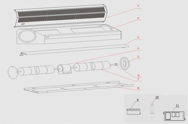
READ ALL INSTRUCTIONS CAREFULLY BEFORE INSTALLING OR USING THIS AIR
CURTAIN.
1. PRODUCT INTRODUCTION
Schwankair's newest top of class high efficiency air curtain provides excellent control of heat/cool
loss in conditioned spaces allowing for lower energy costs. This new series also prevents flying insect
protection. Common uses are retail doors such as restaurants, hotels, shopping malls, storage facilities.
These products are easy to install and comes with a 120V plug, 2 speeds, a remote control and door
switch, coverage for doors 3', 4' & 5' or double up for wider applications.
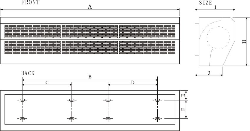
2. IDENTIFICATION & INSTALLATION DIMENSIONS SIDE
A B C D E F H I J
MODEL inches inches inches inches inches inches inches inches inches
[mm] [mm] [mm] [mm] [mm] [mm] [mm] [mm] [mm]
37.20
AC-1036-12-BK --- ---
[945] 17.33
49.21 [440] 2.05 5.71 10.24 8.66 5.12
AC-1048-12-BK --- ---
[1250] [52] [145] [260] [220] [130]
61.18 33.07 --- ---
AC-1060-12-BK
[1554] [840]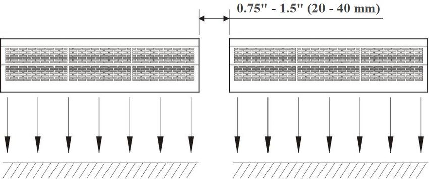
3. INSTALLATION CAUTION

Must follow the following steps to install the 1200 series air curtain:

3.1 Install the unit to a rigid and sturdy structure to   3.2 Units for indoor use only.
avoid shaking. Improper installation location may
cause excessive vibration and noise.

3.3 Do Not install the unit too low, no less than 90      3.4 When the entrance is wider than the unit, it is
inches (2.3 meters) from the ground.                      recommended to install two or more units.
                                                          Provide a gap of 0.75"–1.5" (20–40 mm) between
                                                          units.

3.5 Do Not leave gaps between the unit and the            3.6 Do Not install where unit may be splashed by
wall. When hanging the unit from the ceiling, use         liquid, exposed to excessive steam, or explosive /
the enclosed ceiling brackets.                            corrosive gas.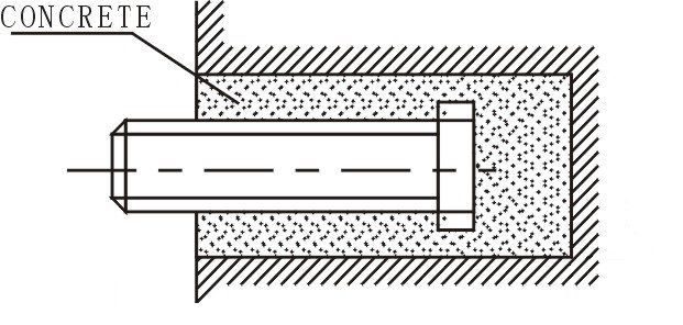
4. INSTALLATION

A.   Installing on a concrete wall:

4.1.1 Remove the mounting plate from the back of      4.1.2 Drill anchor points in the wall and fix the
the air curtain by removing the mounting screws at    bolts in the proper position. Use the mounting
the bottom flange. Retain the mounting screws         plate as a template to mark the fastener locations.

4.1.3 After anchoring the mounting bolts, fit the     4.1.4 Install the main body.
mounting plate (use the washer and nut according      Put the main body on the upper end of the
to the Figure below).                                 mounting plate and clamp it as shown.

B.   Installing on a wood wall:

4.2.1 Fix the mounting plate in the proper position   4.2.2 Same as step 4 of A
with tapping screw.
C.   Hanging from the ceiling:

4.3.1 Remove the mounting plate from the main         4.3.2 Fix ceiling brackets as Figure below
body (Same as step 4.1.1)

4.3.3 Set the mounting plate on the ceiling 4.3.4 Do the same as step A to install the main
brackets and ensure safe installation (use the bolts body.
attached to the ceiling brackets as Figure below).
Use the ceiling brackets to hang from the ceiling;
the position of the mounting plate can be adjusted
within the limit of 4 inches (100 mm).

D.   For above ceiling:

4.4.1 Fix the air curtain same as the procedure for
installing on the concrete wall.                           A IR D U C T

4.4.2 The air duct must be connected to the air
curtain.
5. TECHNICAL PARAMETER

                                                      Max input           Max air
                                                                                          Air volume     Noise
                                 Volt.     Freq        power              speed                                   Net weight
            MODEL                                                                            (cfm)        (dB)
                                 (V~)      (Hz)         (W)                (m/s)
                                                          H      L        H       L        H      L     H    L     lb.    kg

        AC-1036-12-BK                                380        300                       1177   942    67   65   29.8   13.5

        AC-1048-12-BK             120       60       530        450      13       10      1648   1295   69   67   37.5   17

        AC-1060-12-BK                                690        610                       2119   1648   71   69   46.3   21

6. WIRING DIAGRAM

                                         BLUE(BROWN/RED)
                                                                                  BLUE

                                                 (YELLOW)     RECEIVER   RECEIVER BROWN
                                                  ORANGE        I/C         I/O   WHITE
                                                                                  GREY            N
                                                      C                                           L
                                                     YELLOW
                                                    BLACK
                                                    WHITE

                                                  YELLOW-GREEN
                       THERMAL CUT-OUT

                        2 DOUBLE
                          SPEED INFRARED    REMOTE
                                 SPEED INFRARED     CONTROL
                                                REMOTE        WIRING
                                                       CONTROLLED      DIAGRAM
                                                                  WIRING DIAGRAM

7.    OPERATION

7.1 Turn on the power switch
7.2 Select the desired speed:High[H]、Low[L]
7.3 Adjust the directional vane for optimal effect.

8.    CAUTIONS

a) Use the unit at the rated voltage and frequency indicated on the nameplate.
b) Always disconnect the main electrical supply before installing, maintaining, or repairing this equipment.
c) Routine maintenance must be done every year.
d) Never use petrol, benzene, thinner or any other such chemical for clearing the unit.
e) Do Not install the unit within proximity of water or excessive amount of moisture.
f) All electrical wiring and connections MUST be performed by qualified personnel in accordance with the
     National Electrical Code ANSI/NFPA No. 70 or the Canadian Electrical Code CSA Standard C22.1, and
     local codes and regulations.
9. REPLACEMENT PARTS LIST
Items Item Description Parts Number For Model Number
1 Face plate N/A N/A
2 Casing N/A N/A
3 Air guide grill N/A N/A
Motor (36”) JC-0163-36 AC-1036-12-BK
4 Motor (48”) JC-0163-48 AC-1048-12-BK
Motor (60”) JC-0163-60 AC-1060-12-BK
5 Bearing block JC-0141-XX ALL MODELS
6 Bearing JC-0143-XX ALL MODELS
Left wind wheel (36”) JC-0166-36 AC-1036-12-BK
Right wind wheel (36”) JC-0165-36 AC-1036-12-BK
Left wind wheel (48”) JC-0166-48 AC-1048-12-BK
7
Right wind wheel (48”) JC-0165-48 AC-1048-12-BK
Left wind wheel (60”) JC-0166-60 AC-1060-12-BK
Right wind wheel (60”) JC-0165-60 AC-1060-12-BK
8 Installation plate N/A N/A
Remote
9 JC-0122-XX ALL MODELS
controller-Receiver
10 Remote controller-Sender JC-0120-XX ALL MODELS
11 Control Board – PCB JC-0110-XX ALL MODELS10. WARRANTY The Manufacturer warrants that this product is free from defects in material or workmanship under normal use and service subject to the terms of this document. ONE YEAR WARRANTY Subject to the conditions and limitations stated herein, during the term of this limited warranty, we will supply any component part (at our option a new or repaired component part) of the heater as defined below, which the Manufacturer’s examination determines to be defective in workmanship or material for a period of one (1) years from the date of installation, unless otherwise specified below. This warranty applies to the heater’s original owner, and subsequent transferees and only if the unit is installed, operated, and maintained in accordance with the printed instructions accompanying the unit and in compliance with all applicable installation codes and good trade practices. WHAT IS NOT COVERED The Manufacturer shall not be responsible for any expenses, including service, labor, diagnosis, analysis, material or transportation charges incurred during removal or reinstallation of this product, or any of its components or parts. All labor or service charges shall be paid by the owner. This warranty does not cover products improperly installed, misused, exposed to or damaged by negligence, accident, corrosive or contaminating atmosphere, water, excessive thermal shock, impact, abrasion, normal wear due to use, alteration or operation contrary to the owner’s manual or if the serial number has been altered, defaced or removed. This warranty shall not apply if the electrical input to the product varies by more than ±10% of the rated input on the rating plate. The Manufacturer shall not be liable for any default or delay in performance by its warranty caused by any contingency beyond its control, including war, government restrictions, or restraints, strikes, fire, flood, acts of God, or short or reduced supply of raw materials or products. LIMITATIONS AND EXCLUSIONS This document contains all warranties made by the Manufacturer and may not be varied, altered or extended by any person. There are no promises, or agreements extending from the Manufacture other than the statements contained herein. THIS WARRANTY IS IN LIEU OF ALL WARRANTIES EXPRESSED OR IMPLIED, TO THE EXTENT AUTHORIZED BY THE LAWS OF THE JURISDICTION, INCLUDING SPECIFICALLY THE WARRANTIES OR MERCHANTIBILITY OF FITNESS FOR A PARTICULAR PURPOSE. It is understood and agreed that the Manufacturer’s obligation hereunder is limited to repairing or replacing parts determined to be defective as stated above. In no event shall the Manufacturer be responsible for any alleged personal injuries or other special, incidental or consequential damages. As to property damages, contract, tort or other claim the Manufacturer’s responsibility shall not exceed the purchase price paid for the product. All replacement parts will be warranted for the unused portion of the warranty coverage period remaining on the applicable unit. Some Authorities do not allow certain warranty exclusions or limitations on duration of warranty or the exclusions or limitations of incidental or consequential damages. In such cases, the above limitations or exclusions may not apply to you and are not intended to do so where prohibited by law. This warranty gives you specific legal rights. You may also have other rights which vary by jurisdiction.
You can also read