Beyond the Digital Conversion - The Integration of Information Technology and Professional Media 31 March 2014
←
→
Page content transcription
If your browser does not render page correctly, please read the page content below
Beyond the Digital Conversion
 The Integration of Information Technology and Professional Media
 31 March 2014
 The Convergence of 2 Industries - The Adoption of Information Technology by the Professional
 Media Industry
 Report of the SMPTE Study Group on Media Production System Network Architecture

Copyright © 2014 by the Society of Motion Picture and Television Engineers ®, Inc. (SMPTE ®).
All rights reserved.
No part of this publication may be reproduced, stored in a retrieval system, or transmitted
in any form or by any means, with the express written permission of the publisher.
Society of Motion Picture and Television Engineers®
 3 Barker Avenue
 White Plains, NY 10601 USA
 www.smpte.org

 Beyond the Digital Conversion
The Integration of Information Technology and Professional Media
 The Convergence of 2 Industries - The Adoption of Information Technology by the Professional Media Industry

 Report of the SMPTE Study Group on
 Media Production System Network Architecture

 Report of the SMPTE® Study Group on Media Production System Network Architecture, 31 March 2014 Page 1
 © 2014 by the Society of Motion Picture and Television Engineers® (SMPTE®) – All Rights Reserved.
Society of Motion Picture and Television Engineers®
 3 Barker Avenue
 White Plains, NY 10601 USA
 www.smpte.org

 27 March 2014

Table of Contents
1. Introduction ...........................................................................................................................................................7

2. Scope .....................................................................................................................................................................8

3. Introduction to the Professional Media Production Systems ................................................................................8

 3.1. Introduction to the Broadcast Plant (for Information Technology Professionals) ........................................9

 3.1.1. The Typical Broadcast Plant Today ........................................................................................................9

 3.1.2. Today’s Digital Audio and Video Standards .........................................................................................10

 3.1.3. Uncompressed Video over IP Standards..............................................................................................11

 3.2. Typical Use Cases .........................................................................................................................................11

 3.2.1. Television Production Control Room User Requirements and Expectations .......................................11

 3.2.2. Remote Production Truck (OB Van) .....................................................................................................13

 3.2.3. Television Master Control Rooms, User Requirements and Expectations ..........................................13

 3.2.4. Time and Synchronization with IP .......................................................................................................18

 3.2.5. Digital Audio Distribution Over IP ........................................................................................................18

 3.2.6. Edit Rooms ...........................................................................................................................................19

 3.2.7. Remote Feeds from a Live Event .........................................................................................................22

 3.3. Successful Implementations ........................................................................................................................22

 3.3.1. Use of JPEG 2000 over IP at Big Ten Network .....................................................................................22

 3.3.2. Additional Uses of JPEG 2000 over IP ..................................................................................................23

 3.3.3. Electronic News Gathering over Packet Switched Networks...............................................................23

 © 2014 by the Society of Motion Picture and Television Engineers® (SMPTE®) – All Rights Reserved.
Society of Motion Picture and Television Engineers®
 3 Barker Avenue
 White Plains, NY 10601 USA
 www.smpte.org

 3.4. The Requirements of Professional Media Networks ...................................................................................24

 3.4.1. Real-time media delivery vs. file-based workflows .............................................................................25

 3.4.2. Essence vs. control ...............................................................................................................................25

 3.5. Characteristics of Professional Media Systems ...........................................................................................26

4. Managed Networks .............................................................................................................................................27

 4.1. Managed Networks Basics ...........................................................................................................................27

 4.2. Main Features of Managed Networks .........................................................................................................28

 4.3. Administration Aspects ................................................................................................................................29

5. The Convergence of Two Industries ....................................................................................................................30

 5.1. Differences between Professional Media and Information Technology .....................................................30

 5.2. Common Ground .........................................................................................................................................31

6. Information Technology Solutions for Engineered Networks .............................................................................33

 6.1. Network Models and Stacks ........................................................................................................................33

 6.1.1. OSI Model ............................................................................................................................................33

 6.1.2. Internet Protocol (IP) Stack ..................................................................................................................34

 6.1.3. Network Stacks (Conclusion) ...............................................................................................................34

 6.2. IP Addressing ...............................................................................................................................................34

 6.2.1. Subnetting............................................................................................................................................35

 6.2.2. IPv4 and IPv6........................................................................................................................................35

 6.2.3. Address Management ..........................................................................................................................35

 6.2.4. In-band and Out of band management ...............................................................................................36

 6.3. Layer 2 – Data Link Layer .............................................................................................................................36

 6.3.1. Ethernet ...............................................................................................................................................36

 6.3.2. IEEE 802.1 Audio Video Bridging (AVB) ................................................................................................36

 6.3.2.1. IEEE Standard for Layer 2 Transport Protocol for Time Sensitive Applications in a Bridged LAN 39

 © 2014 by the Society of Motion Picture and Television Engineers® (SMPTE®) – All Rights Reserved.
Society of Motion Picture and Television Engineers®
 3 Barker Avenue
 White Plains, NY 10601 USA
 www.smpte.org

 6.3.3. Data Center Bridging ............................................................................................................................39

6.4. Name Resolution .........................................................................................................................................40

 6.4.1. Static Name Assignment ......................................................................................................................40

 6.4.2. Domain Name Services ........................................................................................................................40

 6.4.3. Dynamic Addressing ............................................................................................................................41

 6.4.4. The Handle System ..............................................................................................................................41

6.5. Switching......................................................................................................................................................42

6.6. Routing.........................................................................................................................................................42

 6.6.1. Static Routing .......................................................................................................................................42

 6.6.2. Dynamic Routing ..................................................................................................................................42

6.7. Multicast ......................................................................................................................................................44

6.8. Anycast ........................................................................................................................................................46

6.9. Quality of Service (QoS) ...............................................................................................................................46

 6.9.1. Explicit Congestion Notification (ECN) .................................................................................................46

 6.9.2. Data Center TCP ...................................................................................................................................47

 6.9.3. Congestion Exposure ...........................................................................................................................47

 6.9.4. Priority Queuing ...................................................................................................................................47

6.10. Issues for the Carriage of SDI over IP using SMPTE ST 2022-6 ................................................................48

6.11. Managing Oversubscription .....................................................................................................................49

 6.11.1. Network Oversubscription ...................................................................................................................50

 6.11.2. Hardware Oversubscription .................................................................................................................50

6.12. Network Architecture ..............................................................................................................................50

 6.12.1. Network Elements ...............................................................................................................................50

 6.12.2. Virtual LANs (VLAN) .............................................................................................................................51

 6.12.3. Software Defined Networking (SDN) ...................................................................................................51

 © 2014 by the Society of Motion Picture and Television Engineers® (SMPTE®) – All Rights Reserved.
Society of Motion Picture and Television Engineers®
 3 Barker Avenue
 White Plains, NY 10601 USA
 www.smpte.org

 6.12.4. High Availability ...................................................................................................................................51

 6.13. My Network, Your Network, and Everything in Between (The Cloud) ....................................................52

 6.13.1. What does the Cloud mean for the Media industry? ..........................................................................53

 6.14. Time and Sync Distribution ......................................................................................................................54

 6.14.1. IEEE 1588-2008 Precision Time Protocol .............................................................................................54

 6.14.2. IEEE 802.1AS – Generalized Precision Timing Protocol (gPTP) ............................................................54

 6.14.2.1. SMPTE ST 2059 Family of Standards for Timing Reference .........................................................55

 6.14.2.2. AES67 ...........................................................................................................................................55

 6.15. IP Studio Framework – “Flows and Grains” .............................................................................................55

7. Conclusion and Further SMPTE Action ................................................................................................................57

8. Terms and Acronyms ...........................................................................................................................................59

9. References ...........................................................................................................................................................64

 © 2014 by the Society of Motion Picture and Television Engineers® (SMPTE®) – All Rights Reserved.
Society of Motion Picture and Television Engineers®
 3 Barker Avenue
 White Plains, NY 10601 USA
 www.smpte.org

 ACKNOWLEDGMENTS
 Theodore H. Szypulski, Committee Chair
 Senior Director Technology Research & Standards
 ESPN, Inc.

It has been my privilege to chair this study group, which performed its work admirably between November 2012
and March 2014. I wish to thank all of the participants for their dedication of time and talent to this effort. While
the roster for this group includes over 75 names, there are particular individuals, folks supported by their
employers in many cases, who deserve mention. Their names, and their employers, are listed below. This work
could not have been completed without the dedication of all the participants.

Special thanks to my fellow officers in this committee, Secretary Thomas Kernen of Cisco Systems, and my
colleague at ESPN, and our Document Editor, Steve Posick. Steve has worked untold hours crafting numerous
drafts of this report.

I place myself into the category of the traditional broadcast engineer, and one who has worked for over four
decades on understanding and deploying new professional media systems with ever increasing proportions of IT
based technologies and techniques. It had become clear to me that there existed a dichotomy between my own
cadre (broadcast engineers) and my colleagues in the IT industry. I could see there was a lack of full
understanding, in both camps, of the performance requirements of professional media systems, and the new
technologies being employed therein.

My hope is that folks in both of these groups will develop an appreciation for the knowledge and talents of all
participants in this evolution. I also hope that this report will allow the readers to identify areas where they can
begin to fill in gaps in their own expertise, improving the future for all of us.

Finally, it is clear to me that SMPTE should investigate what its own role is in this future, taking the steps we
recommend in this report to ensure it remains the preeminent leader in worldwide standardization of technologies
used in the Motion Picture and Television industries.

I thank the following for their especially untiring effort in the creation of this report:

 David Baril ESPN, Inc.
 Paul Briscoe Unaffiliated
 Bob Edge Bob Edge TV Consulting
 Thomas Edwards Fox
 Friedrich Gierlinger Institut fuer Rundfunktechnik
 Brad Gilmer Gilmer & Associates, Inc.
 Thomas Kernen Cisco
 Al Kovalik Media Systems Consulting
 Steve Posick ESPN, Inc.
 Felix Poulin European Broadcast Union
 Edward Reuss GoPro
 Stephen Scott Skotel Corporation
 J. Patrick Waddell Harmonic Inc.
 Marc S. Walker Grass Valley US LLC
 Leigh Whitcomb Harris Broadcast

Page 6 of 64 © 2014 by the Society of Motion Picture and Television Engineers® (SMPTE®) – All Rights Reserved.
Society of Motion Picture and Television Engineers®
 3 Barker Avenue
 White Plains, NY 10601 USA
 www.smpte.org

1. Introduction
The design and architecture of Professional Media Networks (PMN) is becoming increasingly important with the
ever-increasing use of shared packet switched networks (PSN). These PMNs are used for applications such as live
contribution and production, post-production, and presentation. Typically these are built upon Internet Protocol
networks and used for the production of media, including the carriage of media essence (audio & video),
metadata, synchronization and control traffic. Where media traffic coexists with other sorts of communication
and business traffic (multi-service networks), it is particularly important to balance the requirements of media
production network traffic with other types of network traffic. This other traffic may or may not be related to the
Professional Media Network workflows.

Although there exist industry accepted best practices for traditional Information Technology (IT) networks, these
best practices were developed from the requirements of IT applications and may not account for the requirements
and the characteristics of Professional Media Networks. At the time of this report, no such best practices
documentation exists for media production networks.

This report is directed to engineering professionals in both the Information Technology and Television/Motion
Picture industries. These two groups have been interacting for the past decades in what has often been referred
to as the "convergence" of IT and Broadcast Engineering.

The report begins with an introduction to the broadcast plant followed by several typical broadcasting use cases.
IT professionals may find these sections useful in order to understand how Broadcasting/Motion Picture
professionals have been designing and building systems with legacy technologies. It is important to understand
the system characteristics and user expectations with these legacy systems. Following the use case section there is
a section on recent successful implementations using IT connectivity and technologies. The next section
consolidates the expected characteristics of legacy systems. A discussion of Managed Networks follows. The
balance of the report then vets myriad IT technologies and practices and describes how these might be configured
to deliver the expected performance and characteristics.

The report concludes with recommended next steps by SMPTE.

A final note to consider before reading this report -- all kinds of technology advance at breakneck speed, and IT is
no exception. The reader is reminded that this report was written in 2013 and 2014, and therefore reflects the
state of the technology at that time. No doubt, as this report ages it will become less useful for understanding
which technologies to consider in designing professional media production networks, and more interesting as a
“time capsule” that captured the current state of things. The reader is reminded that it is vitally important to take
from this report the knowledge and guidance offered today, and to continually stay abreast of the evolution of IT
in the future.

This report includes trade names to illustrate real-world requirements and implementations. These trade names
are used solely as examples, and their mention does not imply any degree of endorsement or recommendation.

© 2014 by the Society of Motion Picture and Television Engineers ® (SMPTE®) – All Rights Reserved. Page 7 of 64
Society of Motion Picture and Television Engineers®
 3 Barker Avenue
 White Plains, NY 10601 USA
 www.smpte.org

2. Scope
This report identifies, documents, and describes the requirements and characteristics of well-designed
Professional Media Networks and makes recommendations pertaining to the identified requirements. Media-
related quality of service may include characteristics such as isochronous streaming, managed latency, and desired
faster and slower than real time performance.

This report also makes recommendations to the Society regarding the further study of and the creation of
engineering documents pertaining to architectural, design and operational requirements identified for media
production systems and their associated networks.

This report does not provide a number of specific cookbook recipes to meet user requirements, but instead
enumerates user requirements in specific use cases, and then outlines characteristics of various technologies.

This report also outlines a number of technology challenges that network architects should be aware of in design
of PMNs but does not attempt to provide specific solutions. Readers should study the use cases and technologies
in order to facilitate their understanding of how to meet expectations of the new system in Professional Media
Networks using packet switched network technologies.

3. Introduction to the Professional Media Production Systems
The Professional Media (PM) industry transformation started decades ago with the adoption of the serial digital
interface (SDI), and is currently in its digital adolescence. The primary focus of digital to IP conversion projects is
the replication of analog behaviors and requirements within the digital domain.

However, the change to all-digital infrastructures offers many opportunities and is changing the way we perceive
and organize media. With the encapsulation of signals into streams and files, these signals can now be duplicated
without limit or loss and many signals can traverse the same physical network fabric simultaneously. The very way
by which media can be controlled has also changed, instead of telling a device to play the media contained within
itself, systems are now being designed to instruct the media to play on any device, essentially changing the
landscape from controlling devices to controlling media. These changes are improving the efficiency of media
systems by allowing for faster than or slower than real-time operations.

The changes are so big that it has taken decades for the PM industry to address reliability, scalability, and
interoperability issues. While there has been an influx of professionals from other technology disciplines into the
PM industry, bringing additional knowledge, there is still a need to improve the mutual understanding of PM-
specific nuances.

Page 8 of 64 © 2014 by the Society of Motion Picture and Television Engineers® (SMPTE®) – All Rights Reserved.
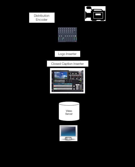
Society of Motion Picture and Television Engineers®
 3 Barker Avenue
 White Plains, NY 10601 USA
 www.smpte.org

3.1. Introduction to the Broadcast Plant (for Information Technology Professionals)
3.1.1. The Typical Broadcast Plant Today
Figure 1 shows a highly simplified block diagram of a typically television broadcast master control. The connection
lines with arrows represent coaxial cables carrying HD-SDI video or AES audio streams.

 Figure 1: Simplified Schematic of Typical Broadcast Master Control

The large cross-point video router is represented as a “U” symbol in this block diagram, but physically it is a
monolithic box with hundreds or thousands of coaxial cable BNC connections for audio and video. The video
router allows video and/or audio from any input to be routed to any output. Router control panels are found
throughout the production plant to control the connections between audio and video sources and destinations.
Facilities may have hundreds or even thousands of devices connected to the video router.

Readers should note the collision of terminology with “router” having a very different meaning than within IT.
There are numerous overloaded terms used by both industries.

The video server is a device for recording and playing back video and audio streams to/from a storage system
(typically spinning hard drives). Servers tend to store video using high visual quality compression.

A video switcher (also known as a vision mixer in Europe) is a device used to select between several
different video sources and to composite/mix them together with effects. Some effects include “fade to black”,
“crossfade” between two video streams, “picture-in-picture”, and 3D video warping.

A Closed Caption Inserter allows for the insertion of live or recorded Closed Caption data into the video stream.

A Logo Inserter is a simple video compositor that adds graphics onto a single video stream.

© 2014 by the Society of Motion Picture and Television Engineers ® (SMPTE®) – All Rights Reserved. Page 9 of 64
Society of Motion Picture and Television Engineers®
 3 Barker Avenue
 White Plains, NY 10601 USA
 www.smpte.org

An Audio Mixer performs the mixing, panning and filtering of multiple audio sources, and generally results in a
final audio mix that is 5.1 channel and/or stereo. Audio/Video devices may also perform some audio mixing during
their video effects (such as a crossfade).

A Distribution Encoder compresses the video into a low-bit rate stream for distribution to television stations
and/or directly to the viewer. The codec used for distribution is typically MPEG-2 or H.264 and is not designed for
a large number of decode/recode cycles. HD video distribution bit rates are typically 15-30 Mbps for MPEG-2.

Not shown in this diagram is the Automation System, which has multiple time-driven event lists used to control a
large number of devices within the plant, especially video servers, for record and playback, and video switchers.
Automation lists can also be manually controlled, for example, in response to a button press that indicates a break
in the action of a sporting event, so that an advertising spot can be run. Automation systems previously used RS-
422 serial communications to control devices, but the industry has been moving toward IP-based control
protocols, with such advancements as the Framework for Interoperable Media Services (FIMS) and the SMPTE ST
2071 standard for Media & Device Control over IP Networks (MDC).

Monitoring includes the displaying of video channels, devices that automatically sense video presence and audio
quiet, devices that monitor audio loudness, and Multi-Viewers that display multiple video sources on a single video
monitor by combing and scaling the video.

3.1.2. Today’s Digital Audio and Video Standards
Although frame rates differ by country high-definition video tends to be found in two primary formats for
television viewing, 1080i and 720p. 1080i consists of 1920x1080 pixel interlaced frames, while 720p consists of
1280x720 pixel progressive frames. Each frame contains a single image, but interlaced frames, indicated by the “i”,
are painted as two fields, each field containing either the odd or the even lines of pixels, while progressive frames,
indicated by the “p”, are painted as a contiguous set of lines of pixels. In 60 Hz power countries that have used the
NTSC standard, 1080i has a frame rate of 30000/1001 fps and 720p has a frame rate of 60/1.001 fps. In 50 Hz
power countries, 1080i has a frame rate of 25 fps and 720p has a frame rate of 50 fps. Other formats are
commonly used in production and consumer media, such as 1080p at 60/1.001 fps and 60 fps, and 1080p at
24/1.001 fps and 24 fps; however, the 24/1.001 fps and 24 fps variants are rarely used in broadcast plants.

HD video signals used within production plants are standardized as SMPTE ST 292-1 (“HD-SDI”), a bit-serial data
structure with a data rate of about 1.5 Gbps. HD-SDI is usually carried over 75Ω coaxial cable, although there is an
optical fiber version (SMPTE ST 297) used mainly for long-distance connections. Uncompressed 4:2:2 chroma
subsampled HDTV signals are transmitted on HD-SDI with 10-bit resolution of each component. Extra, ancillary,
data space outside the active video area within the HD-SDI signal can carry Ancillary data packets (ANC packets).
These Ancillary data packets can include embedded digital audio signals and Closed Captioning data. The HD-SDI
channel coding scheme is scrambled NRZI and there is a CRC value calculated for every active line of video.

SMPTE ST 299-2009 defines the embedding of AES3 24-bit PCM digital audio channels, typically sampled at 48 kHz,
in the horizontal ancillary data space (HANC) of HD-SDI signal. Embedded audio is particularly convenient as it
helps to prevent audio/video lip sync problems that may occur due to timing differences between the audio and
video signal paths.

AES3 audio can also be found in the broadcast plant by itself on audio channel pairs using 75Ω coaxial cable
(AES3id). Broadcast video routers often have dedicated audio inputs and outputs and some also use AES10
Multichannel Audio Digital Interface (MADI) that can carry up to 64 channels of digital audio on a 100 Mbps

 Page 10 of 64 © 2014 by the Society of Motion Picture and Television Engineers® (SMPTE®) – All Rights
 Reserved.
Society of Motion Picture and Television Engineers®
 3 Barker Avenue
 White Plains, NY 10601 USA
 www.smpte.org

network interface. Video routers can have internal audio (de)mux capabilities in order to extract audio channels
from or insert audio channels into the video streams.

3.1.3. Uncompressed Video over IP Standards
SMPTE ST 2022-6 defines the transport of HD-SDI over IP using the Real-Time Transfer Protocol (RTP)[RFC 3550].
SMPTE ST 2022-5 defines a Forward Error Correction (FEC) stream that can provide varying levels of protection
against RTP packet loss for SMPTE ST 2022-6 streams.

There have been some previous RFCs on HD-SDI carriage over IP (such as RFC 3497), but it is believed that SMPTE
ST 2022-6 is an early candidate for the distribution of media essence (audio & video) over IP networks.

3.2. Typical Use Cases
Before a detailed discussion of using packet switched network technologies in Professional Media Systems, it is
wise to offer some examples by way of these use cases. While it is impossible to cover every type of use case,
understanding some of the more common use cases will be helpful to readers who are not already familiar with
Professional Media Systems.

3.2.1. Television Production Control Room User Requirements and Expectations
One example of a facility used extensively in live Television program production is a facility commonly referred to
as a “Production Control Room,” or “PCR.” This use case describes a typical Production Control Room at ESPN’s
worldwide headquarters in Bristol, CT, U.S.A.

The primary purpose of a PCR is to assemble, in real time, all of the elements needed to broadcast a live program.
The control room is typically associated with a Studio or Stage. Often, but not the case at ESPN, an audience is
included in the live Studio.

Video elements consist of live camera signals, prerecorded material from video tape recorders and/or media
servers. Additional video elements include graphics, remote feeds, images from a still storage device, and the
outputs of devices commonly referred to as digital video effects units. Audio elements include live studio
microphones; prerecorded jingles, bridges, etc. from audio servers or audio recording devices; audio from the
video recorders, remote sites, outputs of audio effects equipment, telephone interfaces and others.

The control room of the PCR suite consists of many (typically ten or more) work positions where people
performing the duties of Director, Producer, Technical Director, Graphics Control, Media Playback Control, and
various assistant duties. Usually there is a separate, sound proofed room adjacent to the main control room for
the control of audio. One to three persons reside in the Audio Control Room (ACR) and perform functions of
mixing audio, coordinating with the studio and assistant duties.

Many (typically over 100) video monitors are placed at the front of the control rooms and in consoles in front of
the various work positions to allow workers to view current and upcoming video signals. Some positions employ
various types of “waveform” monitors to view the technical parameters of the video signals. Some positions also
include audio monitors, often used with headphones, which allow the workers to listen to the audio signals. The
audio control room includes high quality audio monitoring, in 5.1 channel surround sound, to ensure the outgoing
signal is correctly mixed. Supplementary audio cuing and monitoring devices are also available.

All signals that are available in the room and that might be made available to the outputs of the room must be
synchronized so that when combined with other signals, or when switched to and from one another, there is no
disruption in the cadence of the signal stream. The output stream MUST be a continuous stream at a constant

 © 2014 by the Society of Motion Picture and Television Engineers ® (SMPTE®) – All Rights Reserved. Page 11 of
 64
Society of Motion Picture and Television Engineers® 3 Barker Avenue White Plains, NY 10601 USA www.smpte.org rate. The audio and video shall be synchronized not only with respect to electrical signal rate, but also by always showing the same moment in time in the audio and video signal. Signals on the various video monitors must always be in “moment of time” synchronization with the audio in the room, within an acceptable margin of error. Many facilities now utilize a composite video monitoring system that combines several images onto one large screen. These systems often introduce a video frame of delay, time needed to process and combine the various images. ESPN has found that the advantages of these systems can be successfully balance with the need for “lip sync” when user expectations are set from the beginning and when the offset is constant and limited to one frame of video. Often during live productions, interviews between persons take place where one person is remotely located. The industry has dealt with latency issues for years due to satellite delays, causing difficulty for people while in a conversation. It is very undesirable to have this situation at all and therefore the addition of more latency, especially varying latency is to be avoided. Summary of user requirements for a PCR: All video and audio signals bound for air must be synchronized with one another. Video to video timing must be within the input buffer window of the video production devices that combine these signals (typically less than the duration of one line of video). Similarly for audio, the signals must be within the input buffer window of the audio mixing device (this is a digital audio requirement). Audio to video “moment in time” match must be less than one frame of video, with the audio never preceding the video. Note: this is often referred to as “lip sync”. Output signals shall be isochronously streamed with a very low latency from the live event, no more than a total of two frames delayed after passing through the entire PCR, ideally less than one frame delayed. Video shall never freeze nor shall audio ever go silent, unless it is a desired effect. There shall be no visible or audible distortions to, or discontinuities of the media streams due to bandwidth restrictions. All signals paths shall have a very high reliability factor. No connection path to the control room, or within the control room, shall be disrupted more than once per year and for a duration of no more than one frame of video. Ideally, no path should ever be disrupted. This restriction applies only to times that the room is being used for production. Media signals meant for monitoring shall be, as much as possible, equal in performance to on-air signals. As monitoring signals are often used for quality evaluation and for confidence and continuity purposes, any changes to them, separate from the on-air signals they represent, might be misinterpreted. When absolutely necessary, audio shall be no more than one frame of video later than the video signal it is associated with. Audio shall never precede the video signal. Signals that send commands to devices shall be delivered without delay, in a deterministic fashion and with latency in the ballpark of a few lines of video, at most. Reaction to the command is expected by the beginning of the next frame of video. When communications amongst workers is delivered via packet switched networks, there shall be no dropped syllables, or any other kinds of distortion that would detract from clear and immediate communications. There shall be no “busy” signals. Signal pathways often incorporate physical “patch bays” or “jackfields” so that the room configuration can be changed from its norm for operational, or for emergency bypass purposes. It is required that packet switched networks also accommodate this physical patching. While traditional connectivity could never offer it, faster-than-real-time delivery of media in and out of servers is a valuable benefit in live control rooms. Being able to load a recently published element very Page 12 of 64 © 2014 by the Society of Motion Picture and Television Engineers® (SMPTE®) – All Rights Reserved.
Society of Motion Picture and Television Engineers®
 3 Barker Avenue
 White Plains, NY 10601 USA
 www.smpte.org

 quickly, providing time for evaluation and cuing, adds immediacy to the workflow, increasing the value of
 the finished media production.

3.2.2. Remote Production Truck (OB Van)
A Remote Production Truck is essentially a complete Production Control Room (as discussed earlier) on wheels. It
is typically a trailer, usually 40 feet (12 meters) in length, towed behind a large diesel powered tractor (truck). It
not only carries the full PCR spaces (both video and audio) but also all of the electronics necessary to make the PCR
function. Additionally it will also carry camera control units (CCUs), often for over a dozen or more cameras.

To help provide additional space for the humans, most production trucks have one or more expandable sections
(called “expando’s”), which often protrude an additional 12 feet (4 meters) beyond the vehicle sides, and
sometimes ends.

During major events there will be a number of trucks, hooked together to provide greater capability than any one
of them alone could. This will typically include a dedicated audio mix truck and often a dedicated graphics and/or
playback truck. For these events, camera control is distributed between those trucks with mounted CCUs.

The working environment within a remote truck is usually noisy, stressful, and cramped. Monitoring, especially
audio monitoring may be suboptimal. Despite the hardships, the programs produced within them are typically first
class.

Remote trucks are used for most live sports, awards shows, and concerts. There are few venues with this
capability built into the building, so a truck is almost always required. While some events backhaul all signals to a
central studio facility, the event still requires a large crew to operate the gear and most importantly deal with
failures or changes at the site in real-time.

3.2.3. Television Master Control Rooms, User Requirements and Expectations
One example of a facility used extensively in Television is a “Master Control Room,” or “Master Control.” Outside
North America, these rooms may be called "Presentation Control Rooms." This use case describes a typical Master
Control Room at any large television network.

The primary purpose of a Master Control Room is to merge pre-recorded and live content into a continuous stream
which is ready to be sent via satellite, terrestrial transmitter, or by other means to affiliates, cable systems and/or
the viewer. The feed is a continuous asynchronous stream with a carefully defined relationship between audio and
video content.

Inputs to a Master Control Room can include the output of video servers, audio/video feeds from a live sports, a
Production Control Room (a PCR), satellite feeds from remote trucks at remote events, playback from video tape
devices, still and moving images and audio associated with graphics and other branding mechanisms, and
importantly, inputs from captioning systems and Emergency Alert Systems (EAS). Note that at the time of this
report, these last two inputs are the only signals U.S. broadcasters are legally required to transmit. Digital video
effects boxes may also be available to create effects such as squeezing back the program video so as to introduce
branding or “coming-up-next” graphics to the transmitted images. Master control facilities may also have the
ability to take an audio-only input such as a phone line in the event of a major equipment failure.

Another critical input to the master control facility is the program schedule, created by the Traffic department.
The traffic department takes the program lineup from the program department, combines it with the promo
schedule from the promotions department, determines the placement of commercials, and then produces the

 © 2014 by the Society of Motion Picture and Television Engineers ® (SMPTE®) – All Rights Reserved. Page 13 of
 64
Society of Motion Picture and Television Engineers®
 3 Barker Avenue
 White Plains, NY 10601 USA
 www.smpte.org

schedule. The program schedule lists every program, commercial, promotional/interstitial item, in short, every
single element that should be combined into the finished program feed, along with the approximate timing for
each event. While the schedule is usually viewed on a computer, many media companies also ensure that a
printed version is available in master control, in the event of system failure.

You may hear several terms used in relation to lists of content for on-air operations such as schedule, playlist, log,
and as-run log. While these may seem interchangeable, they have subtly different meanings. A schedule is a list of
content and approximate times at which the content should air. The term Log may be used interchangeably with
the term schedule. A playlist is a list of content that should play to air, typically contained in an automation
system. A log is a record of what has played and precisely when it played, and an as-run log is a document, or file,
which, after certification, contains the record of what played and precisely when it played for billing purposes.

Typically, a schedule is loaded into an automation system at a particular time of day, although some media
companies are moving to real-time interaction between traffic systems and on-air automation. Once a schedule is
loaded, master control operators check the playlist to ensure that all of the content called for by the list is available
in the system. If it is not, they create a “missing list” and then someone is assigned to track down the missing
content. The automation system plays the content to air and an as-run log is generated for billing purposes. Some
media companies operate their networks according to a strict time-of-day clock. If the schedule says a program
starts at 14:02:00, then that is exactly when the program will start. However, other media companies operate
their networks according to a floating schedule. Start times on the log are approximate, and operators may adjust
schedule timing by inserting interstitial content, dropping items, or the network may insert looping content which
runs continuously, the duration of which can be adjusted by sequencing to the next event at the appropriate time.
However, even these schedules have certain hard times, which must be met. In some applications, video and
audio timing must be extremely closely controlled so that pre-arranged splice points can be met. For example, a
main feed may be split off into a regional feed for a certain portion of the day. When the regional feed rejoins the
main feed, the timing of that switch must be frame accurate, both in video and audio, or unacceptable video
flashes or audio bursts occur.

Since the purpose of a master control operation is to switch between different content streams, the relationship of
the timing between the various input streams must be closely maintained in order to avoid video and audio
artifacts (flashes, cracks and pops, freezing and other undesirable effects). These timing requirements are identical
to those given for a PCR. The original relationship at the source between audio and video streams must be tightly
maintained throughout the master control facility. Master control operations frequently put streams on air that
originate at remote locations, for example, a truck at a baseball game. The truck in the field is likely not using the
same time-base as the master control facility. Therefore, the video and audio timing will drift in phase with
respect to the master control facility clock. Video synchronizers are used to lock the timing of the incoming feed to
the house master reference. These synchronizers delay the video stream. Therefore, audio delay units are
inserted into the corresponding audio streams, and these audio delay units are frequently slaved to the video
synchronizers, automatically introducing a delay in the audio stream that corresponds with the amount of delay
introduced by the video synchronizer.

A number of people typically work in a master control area. There may be a shift supervisor who is responsible for
all of the activities in the area, a master control operator who is responsible for the on-air signal, typically for
several channels, a tape operator who is responsible for ensuring that long-form content is available for air when
needed, and someone working to ingest material, meaning that they are responsible for converting tapes to files
and storing them on fileservers for air, or checking on content delivered to the facility as files prior to approving
them for air. During live sporting events, there may be a live event coordinator who is in communication with
people at the remote event, relaying important information to master control operators. There may also be a
utility person who can fill in for any of these positions during breaks or in case of illness. The number of people
 Page 14 of 64 © 2014 by the Society of Motion Picture and Television Engineers® (SMPTE®) – All Rights
 Reserved.
Society of Motion Picture and Television Engineers®
 3 Barker Avenue
 White Plains, NY 10601 USA
 www.smpte.org

and their job descriptions vary from company to company. Working in a master control area is akin to working in
the operational area of a nuclear power facility. A lot of the work is automated, and the work can be routine.
However, when something goes wrong, only highly trained staff can save your company from a highly visible
disaster.

The master control operator normally operates the facility through an automation system. His or her job is to
check upcoming events to ensure that the automation is properly configured, and to ensure that all content is
available. After that, the operator monitors the automation in case something goes wrong. However, during live
events, the operator may be integrating commercials into the sporting event. This involves not only playing
regularly scheduled commercials during time outs, but also inserting standby schedules in the event of a rain delay,
injury or some other unscheduled event. The automation system is responsible for queuing up the content in
preparation for air, beginning playback of the content, and then selecting that content, usually through a master
control switcher, in order to send the signal to air. In multi-channel facilities, there may not be a master control
switcher control head; but instead, switching may be done through a large Serial Digital Interface (SDI) router. The
automation system also triggers “secondary events”. These events might be insertion of logos, triggering of Digital
Video Effects boxes, or trigger “audio over announcements”, the audio announcements that run over closing
credits promoting upcoming programs.

A Master Control Room has sufficient audio and video monitoring to allow the operator to observe the signal being
sent from the facility and in the case of satellite or terrestrial transmission, there is usually a return monitor, which
is used to verify that the outbound signal is able to be seen by the viewer. There are input monitors that allow the
operator to see sources that can be put on-air, and there are also feeds from PCR suites and other control rooms
that might need to be taken live to air. One critical issue is the synchronization of audio with video, typically called
“lip sync”. Because different monitors have different delays in the time it takes for video to be presented from the
input to the display, many broadcasters have gone to one or two very large displays that are used as Multi-
Viewers. This allows them to compensate for monitor delay in a way that is consistent over all of the displayed
images, something that is difficult or impossible to achieve when using a number of different size displays from
different manufacturers with different internal delays. Note that in some cases broadcasters have given up on
trying to solve this and simply ensure that the delay is correct at the output of the facility and then let the delays in
the master control area be whatever they might be. In this case, lip sync QC is delegated to a special monitoring
area where audio/video delay is known to be correct.

Master control designs tend to be relatively straightforward. An absolute premium is placed on reliability and on
giving the operator relatively simple options in the case of a system failure. For example, it may be possible for the
operator to bypass all master control equipment in order to put a tape machine or fileserver directly to air.
Because in many cases a single operator may be responsible for tens of feeds, automated monitoring and signal
fault analysis tools are frequently employed. These tools detect extended periods of black video, audio silence,
and possibly other more advanced analysis. However, there are some cases where a human being is still a critical
part of the quality assurance process, for example in detecting cases where Spanish and Portuguese language
tracks have been swapped.

Signal integrity is extremely important in a Master Control Room. What goes in must be the same as what comes
out and audio/video synchronization must be tightly controlled. In many cases, master control operators do not
have provisions to adjust audio/video levels. Instead, they rely on the ingest and quality control processes to
ensure that these levels are set correctly before the content is made available for air. To this end, many facilities
embargo content, ensuring that there are areas of fileservers or tape shelves reserved for content which has not
completed the QC process. Once content has completed a QC process, it is made available to the automation
system for playback.

 © 2014 by the Society of Motion Picture and Television Engineers ® (SMPTE®) – All Rights Reserved. Page 15 of
 64
Society of Motion Picture and Television Engineers® 3 Barker Avenue White Plains, NY 10601 USA www.smpte.org One very critical point about modern multi-channel file-based master control rooms is that garbage propagates. Once content is made available for air, automated processes may replicate that content not just on servers in the facility, but potentially to remote facilities, which provide business continuation capabilities. So the old adage, “garbage in, garbage out” is actually “garbage in, garbage everywhere” in these operations. QC is a critical process, and automated QC is frequently employed not only at the ingest point, but also at other places in the system, with the goal of catching garbage before it propagates widely. Another important consideration in master control operations is the importance of a unique identifier. This identifier is sent down from the traffic department in the schedule and is also associated with content as it is ingested into the master control environment. This identifier, historically known as a “house number”, is the key link between computer scheduling systems and automation systems playing back content on air. The main issue with house numbers is that, in many cases, they are not guaranteed to be unique. Another issue is that in many master control environments house numbers themselves convey meaning to operators. This has created a very big liability issue for networks and a lot of human effort is expended to ensure that the correct content gets on air. There are a number of proposed solutions to the house number issue; some of them are quite promising. Any new systems or technologies must take all steps necessary to ensure that identifiers are not corrupted or deleted, whether associated with the content, or with the program schedule data. It is worth mentioning here that networking technology is extensively employed in master control operations. Frequently, files are transferred between video servers using high performance packet switched networks. The master control operation is completely dependent on packet switched networks for the proper operation of the automation systems. Most if not all Master Control Rooms receive some commercial material, which is transmitted to the media company over IP networks, whether terrestrial or via satellite. Most of these operations employ a number of security measures to protect the media company, such as preventing someone from attaching an unauthorized computer to the network or introducing a file infected with a virus into the automation system network. Extreme care is taken in connecting these networks to other networks within the facility, in some cases including an “air gap” between the master control network and other networks, meaning that there is absolutely no connection between master control and other networks within the facility. Summary of user requirements for a Master Control Room: It must work. All the time. “It just works.” Almost everything about master control systems is driven by the “It just works” requirement. Given that once a particular moment in time is past, any revenue opportunities associated with that moment are lost forever and also given the fact that a commercial on a national network may represent tens or even hundreds of thousands of dollars, a huge amount of effort is expended to ensure that there is always a way to get a signal on the air. People responsible for designing and planning master control facilities are risk-averse, with good reason. Operations are kept simple and backup or recovery scenarios are studied, simplified, and practiced. Automated monitoring and QC are required in these facilities, especially multi-channel facilities with centralized ingest operations. The facility must have redundant power feeds from the local power company, fed from diverse locations. Facilities are protected by multiple generators, multiple fuel tanks and multiple uninterruptable power supplies and battery banks. Outgoing paths are redundant, both in terms of equipment and physical location. In this way, outbound paths are protected against “backhoe fades”, otherwise known as fiber cuts caused by a construction crew. All audio and video signals bound for air must be synchronized with one another. Video to video timing must be within the input buffer window of the video production devices that combine these signals, Page 16 of 64 © 2014 by the Society of Motion Picture and Television Engineers® (SMPTE®) – All Rights Reserved.
You can also read