CREATING SOLUTIONS SINCE 1972 - Lock Focus
←
→
Page content transcription
If your browser does not render page correctly, please read the page content below

CREATING SOLUTIONS SINCE 1972
CONTACT US
    PHONE: +61 3 9798 1322
    Email: sales@lockfocus.com.au

    LOCK FOCUS (Head Office)
    15 -17 Futura Road
    Keysborough, 3173
    Victoria, Australia
    Telephone: +61 3 9798 1322
    Email: sales@lockfocus.com.au
    Website: www.lockfocus.com.au

1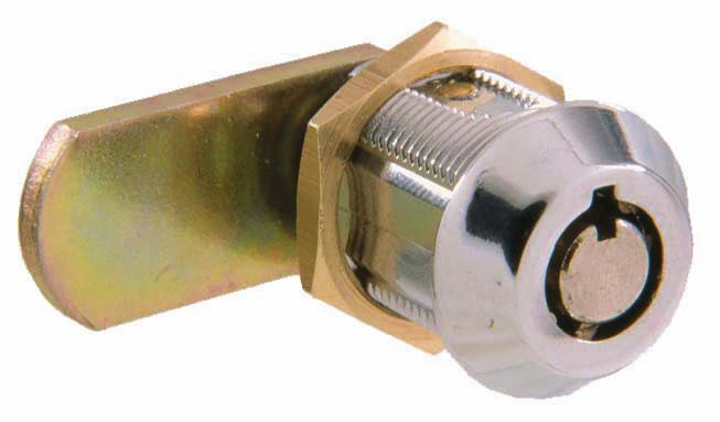
ABOUT US

Lock Focus - Creating Solutions since 1972

 Designs and manufacturers locks for all commercial,
 industrial & residential applications.

Our Melbourne design and manufacturing operations
were established in 1972 and in this time Lock Focus
has developed a modern, world-class facility situated in
the South Eastern suburbs of Melbourne. Lock Focus
has evolved from its origins in the UK more than 100
years ago, to be a major manufacturer of disc tumbler
locks; along with numerous market & customer specific
hardware products; both mechanical & electrical.               Facilities
                                                               Lock Focus operates a facility in Keysborough, Victoria
Employing around 50 people, all manufacturing is               which has the capacity to transform metal bar stock into
currently produced at this single, purpose-built facility      products suitable for all applications in any environment.
utilising the latest automation equipment. The introduction
of automation was a key step to ensuring we consistently       At our facility we design the product, develop the tools,
produce product at high volumes with a high quality at         cast the base product and assemble the end components
customer specific lead times. Due to our success; Lock Focus   to our customer’s specifications. We gain our success
remains as one of the last lock manufacturing companies        through specialising in Zinc Die-casting, Press Shop
in Australia.                                                  manufacturing, Key Automation and Automated Storage
                                                               warehousing.
Lock Focus aims to be the supplier of choice for Original
Equipment Manufacturers (OEM’s), Specifiers and Trade          In recent years we have carefully invested in automating
Retailers by providing tailored locking solutions; supported   our facility and process to reduce our costs of production
by exceptional service.                                        and to ensure we maintain a high level of quality at global
                                                               standards. This also ensures that we can provide a cost
In 2016 Lock Focus was acquired by Safecorp Group, an          effective solution for our customers in a timely manner to
Australian-owned, unlisted public company. Enjoying            match all types of modern day supply demands.
over 30 years of steady profit growth, Safecorp now
ranks in the top 500 Private Companies in Australia and        Our facility is open for customer tours throughout the
has a passion for local Australian manufacturing.              year and we welcome you to come see how we go about
                                                               our business. We have a range of high pressure zinc
Lock Focus has for over 48 years supplied the Australian       diecast machines; a number of presses that process steel
hardware industry brands such as Kiroo, Emka, Lowe &           & brass components; a fully operational tool room; an
Fletcher and Locktech; and is driven to continue to be a       automated key manufacturing system and automated
leading supplier of locks across Australia.                    barrel assembly systems.

                                                                                                                             2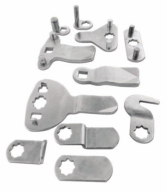
ABOUT US

    Associated Companies & Exclusive Distribution

    Lowe & Fletcher (L&F)

    Lowe & Fletcher design and manufacture locking systems for a broad range of industrial customers. Their locking
    systems range from simple mechanical locks to the latest electronic solutions and can also offer bespoke products,
    enabling Lock Focus to meet diverse locking requirements. L&F’s advanced factory based in the UK supplies locks to
    Ireland, the Middle East, Canada, India, Africa and the Caribbean and totals 70 million locks annually around the world.

    EMKA Group

    The EMKA GROUP is a world leader for locking systems, hinges and sealings, which are used in cabinets and control
    cabinets for electronics and electrical engineering. In the areas of air conditioning technology and transport, EMKA is one
    of the leading manufacturers of total locking technology.

    The product range comprises 15,000 items that are developed, manufactured, processed and assembled at ten production
    sites in Germany, France, England, Spain, Bosnia-Herzegovina, Serbia, China and India. The company supplies 52 countries
    worldwide of which Lock Focus distribute through Australia and New Zealand.

    Eagle Safes

    Eagle Safes was founded in 1972 and quickly earnt a reputation for manufacturing & supplying high quality safes from
    Korea to the rest of the world. As a leader in the Korean safe market Eagle Safes have developed many technologies and
    accumulated a vast amount of know-how. They have played a pivotal role in upgrading the standard of safe manufacturing to
    meet international demands. They support over 100 partners worldwide of which Lock Focus is one.

3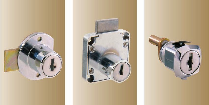
HOW WE WORK

OUR VISION

Lock Focus aims to be the supplier of choice for OEM’s and specifiers by providing tailored locking solutions supported
by exceptional service.

OUR MISSION
We will achieve our mission by:
• Considering our customers in every decision we make.

• Ensuring our customers are our product drivers and that we meet their needs.

• Putting innovation and the product development strategy at the core of what we do.

• Continuously improve our manufacturing methodologies to maintain quality and reduce costs.

• Improve customer service for all mechanical and electronic offerings.

• Developing skills in an enjoyable, safe, healthy and team focused environment.

OUR PROCESS
At Lock Focus we aim to be the supplier of choice for OEM’s: our goal is to provide tailored locking solutions specific to
individual customer requirements. We work with our customers through the following process to achieve the maximum
results:
                                                                                         SUCCESS
                                                                                         WAY TO

          Project         Initial       Targeting      Detailed      Production
         Goals and       Concepts        solution       Design
         Research          and                           and
                        Agreement                      Tooling
                          (SOR)

1.   Project Goals and Research - What is the project purpose, expected outcome & time frame? Initial customer
     interactions, exploratory research & competitor products review.
2.   Initial Concepts and Agreement - Collaborative Statement of Requirements (SOR) Project intent, Design,
     Commitments, Approvals and Initial concepts presentation.
3.   Targeting Solution - Initial CAD concepts, prototyping, client input and review.
4.   Solution Development - Final CAD design, Customer approvals & supply agreements, testing, final customer
     approvals, tooling order, off tool samples (die trials & approvals).
5.   Production - Product release, technical brochures, launch strategy.

                                                                                                                             4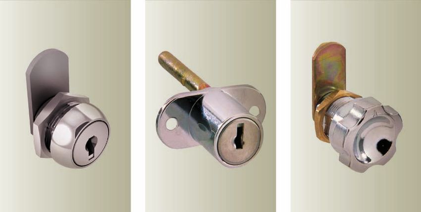
CONTENTS
    Product categories have been colour coded for ease
    of reference. Identify colour on lower corners of each
    product page.

    CABINET AND DRAWER LOCKS

                                                             Bolt Locks . . . . . . . . . . . . . . . . . . . . . . . . . . . . . . . . . . . . . . .   11
                                                             Projection Locks . . . . . . . . . . . . . . . . . . . . . . . . . . . . . . . . . .       15
                                                             Filing Cabinet Locks . . . . . . . . . . . . . . . . . . . . . . . . . . . . . . .         17
                                                             Spindle Locks . . . . . . . . . . . . . . . . . . . . . . . . . . . . . . . . . . . .      19
                                                             Spanner Locks . . . . . . . . . . . . . . . . . . . . . . . . . . . . . . . . . . . .      21

    CAM LOCKS

                                                             Cam Locks 11mm - 32mm . . . . . . . . . . . . . . . . . . . . . . . . . .                  23
                                                             Flange Fix Locks . . . . . . . . . . . . . . . . . . . . . . . . . . . . . . . . . .       27
                                                             Latch Locks . . . . . . . . . . . . . . . . . . . . . . . . . . . . . . . . . . . . . .    30
                                                             Radial Pin Tumbler . . . . . . . . . . . . . . . . . . . . . . . . . . . . . . . .         31
                                                             Accessories . . . . . . . . . . . . . . . . . . . . . . . . . . . . . . . . . . . . . .    32

    DOOR HARDWARE

                                                             Push Locks . . . . . . . . . . . . . . . . . . . . . . . . . . . . . . . . . . . . . . 35
                                                             Cylinders . . . . . . . . . . . . . . . . . . . . . . . . . . . . . . . . . . . . . . . . 39
                                                             Accessories and Multi-Purpose . . . . . . . . . . . . . . . . . . . . . . 42

    GARAGE ROLLER DOOR LOCKS

                                                             Roller Door locks . . . . . . . . . . . . . . . . . . . . . . . . . . . . . . . . . 47

    HANDLES

                                                             Flush Handles . . . . . . . . . . . . . . . . . . . . . . . . . . . . . . . . . . .        55
                                                             Swing Handles . . . . . . . . . . . . . . . . . . . . . . . . . . . . . . . . . . .        57
                                                             T & L Handles . . . . . . . . . . . . . . . . . . . . . . . . . . . . . . . . . . . .      59
                                                             T & L Handles - Pin Cylinder . . . . . . . . . . . . . . . . . . . . . . . .               64
                                                             Compression Latch . . . . . . . . . . . . . . . . . . . . . . . . . . . . . . .            65

5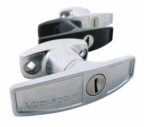
CONTENTS
LOCKTECH
Asset Management System . . . . . . . . . . . . . . . . . . . . . . . . . 67
Electronic Locks . . . . . . . . . . . . . . . . . . . . . . . . . . . . . . . . . . 68
SPECIAL APPLICATION
Bin Locks . . . . . . . . . . . . . . . . . . . . . . . . . . . . . . . . . . . . . . . . 71
Industrial Bin Lock - A/LIDI . . . . . . . . . . . . . . . . . . . . . . . . . 72
32mm - 50mm Water Meter Locks . . . . . . . . . . . . . . . . . . . 73
20mm - 25mm Water Meter Locks . . . . . . . . . . . . . . . . . . . 74
Tap Lock . . . . . . . . . . . . . . . . . . . . . . . . . . . . . . . . . . . . . . . . . 75
Hydrant G Lock . . . . . . . . . . . . . . . . . . . . . . . . . . . . . . . . . . . 75
Commercial Bi-Fold Lock . . . . . . . . . . . . . . . . . . . . . . . . . . 76
Padlock . . . . . . . . . . . . . . . . . . . . . . . . . . . . . . . . . . . . . . . . . 76
Class B/Class C Locks . . . . . . . . . . . . . . . . . . . . . . . . . . . . . 77
UTE Canopy Lock . . . . . . . . . . . . . . . . . . . . . . . . . . . . . . . . . 78
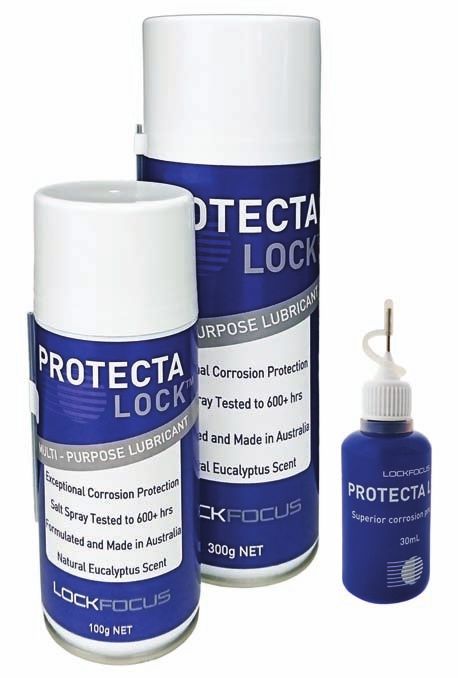
Protecta Lock . . . . . . . . . . . . . . . . . . . . . . . . . . . . . . . . . . . . 79
WINDOW LOCKS
Sash Locks . . . . . . . . . . . . . . . . . . . . . . . . . . . . . . . . . . . . . . 81
Sliding Window Locks . . . . . . . . . . . . . . . . . . . . . . . . . . . . . 83
Push and Twist Vent Lock . . . . . . . . . . . . . . . . . . . . . . . . . . 83
Multi-Purpose Locks . . . . . . . . . . . . . . . . . . . . . . . . . . . . . . 84
Window Push Lock . . . . . . . . . . . . . . . . . . . . . . . . . . . . . . . . 84
Window and Mini Window Bolt . . . . . . . . . . . . . . . . . . . . . . 85
Casement Awning Latch . . . . . . . . . . . . . . . . . . . . . . . . . . . 85
APPENDIX A
Pressed Cam Range . . . . . . . . . . . . . . . . . . . . . . . . . . . . . . . 87
APPENDIX B - MOVEMENT
General . . . . . . . . . . . . . . . . . . . . . . . . . . . . . . . . . . . . . . . . . 92
Bin Locks . . . . . . . . . . . . . . . . . . . . . . . . . . . . . . . . . . . . . . . . 92
C Movement Camlock . . . . . . . . . . . . . . . . . . . . . . . . . . . . . . 92
WARRANTY
Warranty /Guarantee . . . . . . . . . . . . . . . . . . . . . . . . . . . . . . 93
Terms & Conditions . . . . . . . . . . . . . . . . . . . . . . . . . . . . . . . 94
Privacy Policy . . . . . . . . . . . . . . . . . . . . . . . . . . . . . . . . . . . . . 95
Contact Us . . . . . . . . . . . . . . . . . . . . . . . . . . . . . . . . . . . . . . . 98
6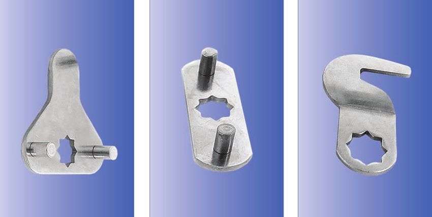
CONTENTS

      CABINET AND DRAWER LOCKS                                                                                                    CAM LOCKS cont.
    BOLT LOCKS . . . . . . . . . . . . . . . . . . . . . . . . . . . . . . . . . . . . . . . . . . . . . . . . . . . .     11   FLANGE FIX LOCKS . . . . . . . . . . . . . . . . . . . . . . . . . . . . . . . . . . . . . . . . . . . . . .                   27
    Quick Reference Guide . . . . . . . . . . . . . . . . . . . . . . . . . . . . . . . . . . . . . . . . . . . .          11   Quick Reference Guide . . . . . . . . . . . . . . . . . . . . . . . . . . . . . . . . . . . . . . . . . . .                    27
    Bolt Options B & C . . . . . . . . . . . . . . . . . . . . . . . . . . . . . . . . . . . . . . . . . . . . . . .       12   Installation Instructions . . . . . . . . . . . . . . . . . . . . . . . . . . . . . . . . . . . . . . . . . .                  28
    Bolt Options F & R . . . . . . . . . . . . . . . . . . . . . . . . . . . . . . . . . . . . . . . . . . . . . . .       12   Back Fix Horizontal Mount . . . . . . . . . . . . . . . . . . . . . . . . . . . . . . . . . . . . . . . .                      28
    Fixing Details for Bolt Locks . . . . . . . . . . . . . . . . . . . . . . . . . . . . . . . . . . . . . . .            12   Multi Drawer . . . . . . . . . . . . . . . . . . . . . . . . . . . . . . . . . . . . . . . . . . . . . . . . . . . .           28
                                                                                                                                Multi Drawer Single Flange . . . . . . . . . . . . . . . . . . . . . . . . . . . . . . . . . . . . . . .                       28
    19mm & 22mm Vertical Projection Bolts . . . . . . . . . . . . . . . . . . . . . . . . . . . . .                        13
                                                                                                                                Multi Drawer Back Fix Vertical Mount . . . . . . . . . . . . . . . . . . . . . . . . . . . . . . .                             29
    22mm Vertical Projection Bolt - Barrel Exchange . . . . . . . . . . . . . . . . . . . . . .                            13
                                                                                                                                Back Fix Vertical Mount - Barrel Exchange . . . . . . . . . . . . . . . . . . . . . . . . . . .                                29
    19mm & 22mm Right/Left Projection Bolts . . . . . . . . . . . . . . . . . . . . . . . . . . .                          13   Back Fix Horizontal Mount - Barrel Exchange . . . . . . . . . . . . . . . . . . . . . . . .                                    29
    22mm Right/Left Projection Bolt - Barrel Exchange . . . . . . . . . . . . . . . . . . .                                13
    C4 Universal Drawer Bolt . . . . . . . . . . . . . . . . . . . . . . . . . . . . . . . . . . . . . . . . .             14   LATCH LOCKS . . . . . . . . . . . . . . . . . . . . . . . . . . . . . . . . . . . . . . . . . . . . . . . . . . . 30
    Fixing Details for C4 Bolt . . . . . . . . . . . . . . . . . . . . . . . . . . . . . . . . . . . . . . . . . .         14   Latch Lock 16mm . . . . . . . . . . . . . . . . . . . . . . . . . . . . . . . . . . . . . . . . . . . . . . . . 30
                                                                                                                                Latch Lock 19mm . . . . . . . . . . . . . . . . . . . . . . . . . . . . . . . . . . . . . . . . . . . . . . . . 30
    PROJECTION LOCKS . . . . . . . . . . . . . . . . . . . . . . . . . . . . . . . . . . . . . . . . . . . . .             15
    Quick Reference Guide . . . . . . . . . . . . . . . . . . . . . . . . . . . . . . . . . . . . . . . . . . . .          15   RADIAL PIN TUMBLER . . . . . . . . . . . . . . . . . . . . . . . . . . . . . . . . . . . . . . . . . . . 31
    Fixing Details for Square Back Bolt . . . . . . . . . . . . . . . . . . . . . . . . . . . . . . . . .                  16
                                                                                                                                ACCESSORIES . . . . . . . . . . . . . . . . . . . . . . . . . . . . . . . . . . . . . . . . . . . . . . . . . .                32
    Fixing Details for 6mm/20mm Lever Lock . . . . . . . . . . . . . . . . . . . . . . . . . . . .                         16
                                                                                                                                Camlock Spacer - T/SPAC . . . . . . . . . . . . . . . . . . . . . . . . . . . . . . . . . . . . . . . .                        32
    Square Back Bolt with Vertical Projection . . . . . . . . . . . . . . . . . . . . . . . . . . . .                      16   Camlock Flat Washer - O/CWFL . . . . . . . . . . . . . . . . . . . . . . . . . . . . . . . . . . . .                           32
    Square Back Bolt with Left Projection . . . . . . . . . . . . . . . . . . . . . . . . . . . . . . .                    16   Camlock Prong Washer - O/CWPR . . . . . . . . . . . . . . . . . . . . . . . . . . . . . . . . . .                              32
    Square Back Bolt with Right Projection . . . . . . . . . . . . . . . . . . . . . . . . . . . . . .                     16   Hamper/Tambour Door Lock - M/CAM P6 and M/STRK P6 . . . . . . . . . . . . . .                                                  32
    Vertical/Left/Right Projection-Barrel Exchange . . . . . . . . . . . . . . . . . . . . . . .                           16   Bezels . . . . . . . . . . . . . . . . . . . . . . . . . . . . . . . . . . . . . . . . . . . . . . . . . . . . . . . . .       32
    6mm Lever Lock . . . . . . . . . . . . . . . . . . . . . . . . . . . . . . . . . . . . . . . . . . . . . . . . .       16
    22mm Lever Lock . . . . . . . . . . . . . . . . . . . . . . . . . . . . . . . . . . . . . . . . . . . . . . . .        16

    FILING CABINET LOCKS . . . . . . . . . . . . . . . . . . . . . . . . . . . . . . . . . . . . . . . . . .               17     DOOR HARDWARE
    Quick Reference Guide . . . . . . . . . . . . . . . . . . . . . . . . . . . . . . . . . . . . . . . . . . . .          17
    Fixing Details . . . . . . . . . . . . . . . . . . . . . . . . . . . . . . . . . . . . . . . . . . . . . . . . . . .   18   PUSH LOCKS . . . . . . . . . . . . . . . . . . . . . . . . . . . . . . . . . . . . . . . . . . . . . . . . . . .               35
    19mm Round Face . . . . . . . . . . . . . . . . . . . . . . . . . . . . . . . . . . . . . . . . . . . . . . .          18   Quick Reference Guide . . . . . . . . . . . . . . . . . . . . . . . . . . . . . . . . . . . . . . . . . . .                    35
    19mm Square Face . . . . . . . . . . . . . . . . . . . . . . . . . . . . . . . . . . . . . . . . . . . . . . .         18   12mm throw Zinc . . . . . . . . . . . . . . . . . . . . . . . . . . . . . . . . . . . . . . . . . . . . . . . .                36
    20mm Round Face . . . . . . . . . . . . . . . . . . . . . . . . . . . . . . . . . . . . . . . . . . . . . . .          18   12mm throw S/S . . . . . . . . . . . . . . . . . . . . . . . . . . . . . . . . . . . . . . . . . . . . . . . .                 36
    20mm Square Face . . . . . . . . . . . . . . . . . . . . . . . . . . . . . . . . . . . . . . . . . . . . . .           18
                                                                                                                                11mm throw . . . . . . . . . . . . . . . . . . . . . . . . . . . . . . . . . . . . . . . . . . . . . . . . . . . .             37
    20mm Flat Face . . . . . . . . . . . . . . . . . . . . . . . . . . . . . . . . . . . . . . . . . . . . . . . . .       18
                                                                                                                                Projection Pin . . . . . . . . . . . . . . . . . . . . . . . . . . . . . . . . . . . . . . . . . . . . . . . . . . .           37
    20mm Barrel Exchange . . . . . . . . . . . . . . . . . . . . . . . . . . . . . . . . . . . . . . . . . . .             18
                                                                                                                                Material/Fixing Code . . . . . . . . . . . . . . . . . . . . . . . . . . . . . . . . . . . . . . . . . . . . .                 37
    SPINDLE LOCKS . . . . . . . . . . . . . . . . . . . . . . . . . . . . . . . . . . . . . . . . . . . . . . . . .        19   PP5 Front/Rear Fix Cover . . . . . . . . . . . . . . . . . . . . . . . . . . . . . . . . . . . . . . . . .                     38
    Quick Reference Guide . . . . . . . . . . . . . . . . . . . . . . . . . . . . . . . . . . . . . . . . . . . .          19   PP5 Front Fix Cover - S/S . . . . . . . . . . . . . . . . . . . . . . . . . . . . . . . . . . . . . . . . .                    38
    Fixing Details for 19mm & 20mm Spindle Locks . . . . . . . . . . . . . . . . . . . . . . .                             20
    19mm Spindle Lock . . . . . . . . . . . . . . . . . . . . . . . . . . . . . . . . . . . . . . . . . . . . . .          20   CYLINDERS . . . . . . . . . . . . . . . . . . . . . . . . . . . . . . . . . . . . . . . . . . . . . . . . . . . . .            39
    19mm Spindle Lock Slamlock . . . . . . . . . . . . . . . . . . . . . . . . . . . . . . . . . . . . . .                 20   Quick Reference Guide . . . . . . . . . . . . . . . . . . . . . . . . . . . . . . . . . . . . . . . . . . . .                  39
    20mm Spindle Lock . . . . . . . . . . . . . . . . . . . . . . . . . . . . . . . . . . . . . . . . . . . .. .           20   AD4 . . . . . . . . . . . . . . . . . . . . . . . . . . . . . . . . . . . . . . . . . . . . . . . . . . . . . . . . . . .      40
                                                                                                                                AD6 . . . . . . . . . . . . . . . . . . . . . . . . . . . . . . . . . . . . . . . . . . . . . . . . . . . . . . . . . . .      40
    SPANNER LOCKS . . . . . . . . . . . . . . . . . . . . . . . . . . . . . . . . . . . . . . . . . . . . . . . . 21            AD7 . . . . . . . . . . . . . . . . . . . . . . . . . . . . . . . . . . . . . . . . . . . . . . . . . . . . . . . . . . .      40
    Key Lockable Spanner Lock . . . . . . . . . . . . . . . . . . . . . . . . . . . . . . . . . . . . . . . 21                  AD8 . . . . . . . . . . . . . . . . . . . . . . . . . . . . . . . . . . . . . . . . . . . . . . . . . . . . . . . . . . .      41
    Spanner Lock . . . . . . . . . . . . . . . . . . . . . . . . . . . . . . . . . . . . . . . . . . . . . . . . . . . 21       AT1-4 . . . . . . . . . . . . . . . . . . . . . . . . . . . . . . . . . . . . . . . . . . . . . . . . . . . . . . . . . .      41

                                                                                                                                ACCESSORIES AND MULTI-PURPOSE . . . . . . . . . . . . . . . . . . . . . . . . . . . . . . .                                    42
                                                                                                                                Flush Mounting Tabs . . . . . . . . . . . . . . . . . . . . . . . . . . . . . . . . . . . . . . . . . . . . .                  42
      CAM LOCKS                                                                                                                 Security Cylinder Trim . . . . . . . . . . . . . . . . . . . . . . . . . . . . . . . . . . . . . . . . . . . .                 42
                                                                                                                                Patio Bolt . . . . . . . . . . . . . . . . . . . . . . . . . . . . . . . . . . . . . . . . . . . . . . . . . . . . . . .       43
    CAM LOCKS 11mm - 32mm . . . . . . . . . . . . . . . . . . . . . . . . . . . . . . . . . . . . . . .                    23   Euclid200 . . . . . . . . . . . . . . . . . . . . . . . . . . . . . . . . . . . . . . . . . . . . . . . . . . . . . . .        44
    Quick Reference Guide . . . . . . . . . . . . . . . . . . . . . . . . . . . . . . . . . . . . . . . . . . .            23
    Installation Cut-Out, 11-16mm Camlock . . . . . . . . . . . . . . . . . . . . . . . . . . . . .                        24
    11mm Cam Lock Round Face . . . . . . . . . . . . . . . . . . . . . . . . . . . . . . . . . . . . . .                   24
    11mm Cam Lock Square Face . . . . . . . . . . . . . . . . . . . . . . . . . . . . . . . . . . . . .                    24     GARAGE ROLLER DOOR LOCKS
    16mm Cam Lock Round Face . . . . . . . . . . . . . . . . . . . . . . . . . . . . . . . . . . . . . .                   24
    16mm Cam Lock Square Face . . . . . . . . . . . . . . . . . . . . . . . . . . . . . . . . . . . . .                    24   ROLLER DOOR LOCKS . . . . . . . . . . . . . . . . . . . . . . . . . . . . . . . . . . . . . . . . . . . .                      47
    19mm Cam Lock Round Face . . . . . . . . . . . . . . . . . . . . . . . . . . . . . . . . . . . . . .                   25   Quick Reference Guide . . . . . . . . . . . . . . . . . . . . . . . . . . . . . . . . . . . . . . . . . . . .                  47
    19mm Cam Lock Square Face . . . . . . . . . . . . . . . . . . . . . . . . . . . . . . . . . . . . .                    25   Internal Latch Override . . . . . . . . . . . . . . . . . . . . . . . . . . . . . . . . . . . . . . . . . . .                  48
    19mm Cam Lock Round Face Quick fix . . . . . . . . . . . . . . . . . . . . . . . . . . . . . .                         25   V9C4 & V9LP Freelatch vs Deadlocking . . . . . . . . . . . . . . . . . . . . . . . . . . . . . .                               48
    19mm Cam Lock Square Face Quick fix . . . . . . . . . . . . . . . . . . . . . . . . . . . . . .                        25   V1 . . . . . . . . . . . . . . . . . . . . . . . . . . . . . . . . . . . . . . . . . . . . . . . . . . . . . . . . . . . . .   49
    20mm Cam Lock (Slim Face) Round Face . . . . . . . . . . . . . . . . . . . . . . . . . . . .                           25   V2 . . . . . . . . . . . . . . . . . . . . . . . . . . . . . . . . . . . . . . . . . . . . . . . . . . . . . . . . . . . . .   49
                                                                                                                                V3 . . . . . . . . . . . . . . . . . . . . . . . . . . . . . . . . . . . . . . . . . . . . . . . . . . . . . . . . . . . . .   50
    20mm Cam Lock (Slim Face) Square Face . . . . . . . . . . . . . . . . . . . . . . . . . . .                            25
                                                                                                                                V4 . . . . . . . . . . . . . . . . . . . . . . . . . . . . . . . . . . . . . . . . . . . . . . . . . . . . . . . . . . . . .   50
    20mm Cam Lock (Slim Face) Round Face Quick fix . . . . . . . . . . . . . . . . . . . .                                 25
                                                                                                                                V5 . . . . . . . . . . . . . . . . . . . . . . . . . . . . . . . . . . . . . . . . . . . . . . . . . . . . . . . . . . . . .   51
    20mm Cam Lock (Slim Face) Square Face Quick fix . . . . . . . . . . . . . . . . . . . .                                25   V7 . . . . . . . . . . . . . . . . . . . . . . . . . . . . . . . . . . . . . . . . . . . . . . . . . . . . . . . . . . . . .   51
    20mm Barrel Exchange Cam Lock Round Face . . . . . . . . . . . . . . . . . . . . . . .                                 25   V9 . . . . . . . . . . . . . . . . . . . . . . . . . . . . . . . . . . . . . . . . . . . . . . . . . . . . . . . . . . . . .   52
    22mm Cam Lock Round Face . . . . . . . . . . . . . . . . . . . . . . . . . . . . . . . . . . . . . .                   26   V9C4 . . . . . . . . . . . . . . . . . . . . . . . . . . . . . . . . . . . . . . . . . . . . . . . . . . . . . . . . . . .     52
    32mm Cam Lock Round Face . . . . . . . . . . . . . . . . . . . . . . . . . . . . . . . . . . . . . .                   26   V9LP . . . . . . . . . . . . . . . . . . . . . . . . . . . . . . . . . . . . . . . . . . . . . . . . . . . . . . . . . . .     52

7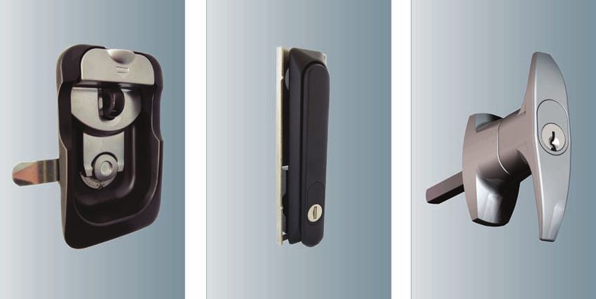
CONTENTS

  HANDLES                                                                                                                           SPECIAL APPLICATION cont.
FLUSH HANDLES . . . . . . . . . . . . . . . . . . . . . . . . . . . . . . . . . . . . . . . . . . . . . . . .                55   Class B . . . . . . . . . . . . . . . . . . . . . . . . . . . . . . . . . . . . . . . . . . . . . . . . . . . . . . . . 77
Quick Reference Guide . . . . . . . . . . . . . . . . . . . . . . . . . . . . . . . . . . . . . . . . . . . .                55   Class C . . . . . . . . . . . . . . . . . . . . . . . . . . . . . . . . . . . . . . . . . . . . . . . . . . . . . . . . 77
Installation Instructions . . . . . . . . . . . . . . . . . . . . . . . . . . . . . . . . . . . . . . . . . . .              56   UTE CANOPY LOCK . . . . . . . . . . . . . . . . . . . . . . . . . . . . . . . . . . . . . . . . . . . . . . 78
Plastic/Metal Pan . . . . . . . . . . . . . . . . . . . . . . . . . . . . . . . . . . . . . . . . . . . . . . . .            56
C4 Pan . . . . . . . . . . . . . . . . . . . . . . . . . . . . . . . . . . . . . . . . . . . . . . . . . . . . . . . . .     56   PROTECTA LOCK . . . . . . . . . . . . . . . . . . . . . . . . . . . . . . . . . . . . . . . . . . . . . . . . 79
Pad Lockable-Heavy Duty Latch Lock . . . . . . . . . . . . . . . . . . . . . . . . . . . . . . .                             56

SWING HANDLES . . . . . . . . . . . . . . . . . . . . . . . . . . . . . . . . . . . . . . . . . . . . . . . .                57     WINDOW LOCKS
Quick Reference Guide . . . . . . . . . . . . . . . . . . . . . . . . . . . . . . . . . . . . . . . . . . . .                57
Installation Instructions . . . . . . . . . . . . . . . . . . . . . . . . . . . . . . . . . . . . . . . . . . .              58   SASH LOCKS . . . . . . . . . . . . . . . . . . . . . . . . . . . . . . . . . . . . . . . . . . . . . . . . . . . .           81
HS741-HS744 . . . . . . . . . . . . . . . . . . . . . . . . . . . . . . . . . . . . . . . . . . . . . . . . . . .            58   Quick Reference Guides . . . . . . . . . . . . . . . . . . . . . . . . . . . . . . . . . . . . . . . . . . .                 81
F736-F737 . . . . . . . . . . . . . . . . . . . . . . . . . . . . . . . . . . . . . . . . . . . . . . . . . . . . . .        58   Strike Options . . . . . . . . . . . . . . . . . . . . . . . . . . . . . . . . . . . . . . . . . . . . . . . . . . .         82
F738 . . . . . . . . . . . . . . . . . . . . . . . . . . . . . . . . . . . . . . . . . . . . . . . . . . . . . . . . . . .   58   DH90 . . . . . . . . . . . . . . . . . . . . . . . . . . . . . . . . . . . . . . . . . . . . . . . . . . . . . . . . . . .   82
T & L HANDLES . . . . . . . . . . . . . . . . . . . . . . . . . . . . . . . . . . . . . . . . . . . . . . . . .              59   DH180 . . . . . . . . . . . . . . . . . . . . . . . . . . . . . . . . . . . . . . . . . . . . . . . . . . . . . . . . . .    82
Quick Reference Guide . . . . . . . . . . . . . . . . . . . . . . . . . . . . . . . . . . . . . . . . . . . .                59   Sash Lift Handle . . . . . . . . . . . . . . . . . . . . . . . . . . . . . . . . . . . . . . . . . . . . . . . . .           82
Assembly Instructions . . . . . . . . . . . . . . . . . . . . . . . . . . . . . . . . . . . . . . . . . . . .                60   SLIDING WINDOW LOCKS . . . . . . . . . . . . . . . . . . . . . . . . . . . . . . . . . . . . . . . . . 83
Spindles . . . . . . . . . . . . . . . . . . . . . . . . . . . . . . . . . . . . . . . . . . . . . . . . . . . . . . . .     60
T & L Handles - Cams, Spindles and Rotation . . . . . . . . . . . . . . . . . . . . . . . . .                                61   PUSH AND TWIST VENT LOCK . . . . . . . . . . . . . . . . . . . . . . . . . . . . . . . . . . . . . . 83
T & L Handles - Cams, Spindles and Movement . . . . . . . . . . . . . . . . . . . . . . .                                    62   MULTI-PURPOSE LOCKS . . . . . . . . . . . . . . . . . . . . . . . . . . . . . . . . . . . . . . . . . . 84
Large T Handle . . . . . . . . . . . . . . . . . . . . . . . . . . . . . . . . . . . . . . . . . . . . . . . . . .           63
Small T Handle . . . . . . . . . . . . . . . . . . . . . . . . . . . . . . . . . . . . . . . . . . . . . . . . . .           63   WINDOW PUSH LOCK . . . . . . . . . . . . . . . . . . . . . . . . . . . . . . . . . . . . . . . . . . . . . 84
Lever Handles . . . . . . . . . . . . . . . . . . . . . . . . . . . . . . . . . . . . . . . . . . . . . . . . . . .          63   WINDOW AND MINI WINDOW BOLT . . . . . . . . . . . . . . . . . . . . . . . . . . . . . . . . . 85
Lever Handle - Padlocking . . . . . . . . . . . . . . . . . . . . . . . . . . . . . . . . . . . . . . . . .                  63
                                                                                                                                  CASEMENT AWNING LATCH . . . . . . . . . . . . . . . . . . . . . . . . . . . . . . . . . . . . . . . 85
T & L HANDLES - PIN CYLINDER . . . . . . . . . . . . . . . . . . . . . . . . . . . . . . . . . . .                           64
Assembly Instructions . . . . . . . . . . . . . . . . . . . . . . . . . . . . . . . . . . . . . . . . . . . .                64
L Handle . . . . . . . . . . . . . . . . . . . . . . . . . . . . . . . . . . . . . . . . . . . . . . . . . . . . . . .       64     APPENDIX A
T Handle . . . . . . . . . . . . . . . . . . . . . . . . . . . . . . . . . . . . . . . . . . . . . . . . . . . . . . .       64

COMPRESSION LATCH . . . . . . . . . . . . . . . . . . . . . . . . . . . . . . . . . . . . . . . . . . . . 65                      PRESSED CAM RANGE . . . . . . . . . . . . . . . . . . . . . . . . . . . . . . . . . . . . . . . . . . . .                    87
                                                                                                                                  Cam Types . . . . . . . . . . . . . . . . . . . . . . . . . . . . . . . . . . . . . . . . . . . . . . . . . . . . . .        87
                                                                                                                                  Product Options . . . . . . . . . . . . . . . . . . . . . . . . . . . . . . . . . . . . . . . . . . . . . . . . .            87
  LOCKTECH                                                                                                                        Flat Cams . . . . . . . . . . . . . . . . . . . . . . . . . . . . . . . . . . . . . . . . . . . . . . . . . . . . . .        88
                                                                                                                                  Single Bend Cams . . . . . . . . . . . . . . . . . . . . . . . . . . . . . . . . . . . . . . . . . . . . . . . .             88
ASSET MANAGEMENT SYSTEM . . . . . . . . . . . . . . . . . . . . . . . . . . . . . . . . . . . . 67                                Double Bend Cams . . . . . . . . . . . . . . . . . . . . . . . . . . . . . . . . . . . . . . . . . . . . . . .               88
                                                                                                                                  Double Bend Cams cont. . . . . . . . . . . . . . . . . . . . . . . . . . . . . . . . . . . . . . . . . . .                   89
ELECTRONIC LOCKS . . . . . . . . . . . . . . . . . . . . . . . . . . . . . . . . . . . . . . . . . . . . . 68
                                                                                                                                  Bent S Cams . . . . . . . . . . . . . . . . . . . . . . . . . . . . . . . . . . . . . . . . . . . . . . . . . . . .          89
                                                                                                                                  Hooked Cams . . . . . . . . . . . . . . . . . . . . . . . . . . . . . . . . . . . . . . . . . . . . . . . . . . .            89
                                                                                                                                  Single Point Pinned - T . . . . . . . . . . . . . . . . . . . . . . . . . . . . . . . . . . . . . . . . . . . .              89
  SPECIAL APPLICATION                                                                                                             Single Point Pinned - A . . . . . . . . . . . . . . . . . . . . . . . . . . . . . . . . . . . . . . . . . . . .              89
                                                                                                                                  2 Point Pinned . . . . . . . . . . . . . . . . . . . . . . . . . . . . . . . . . . . . . . . . . . . . . . . . . . .         90
BIN LOCKS . . . . . . . . . . . . . . . . . . . . . . . . . . . . . . . . . . . . . . . . . . . . . . . . . . . . .          71   3 Point Pinned - A . . . . . . . . . . . . . . . . . . . . . . . . . . . . . . . . . . . . . . . . . . . . . . . .           90
Quick Reference Guide . . . . . . . . . . . . . . . . . . . . . . . . . . . . . . . . . . . . . . . . . . . .                71   3 Point Pinned - T . . . . . . . . . . . . . . . . . . . . . . . . . . . . . . . . . . . . . . . . . . . . . . . .           90
Gravity Lid Lock . . . . . . . . . . . . . . . . . . . . . . . . . . . . . . . . . . . . . . . . . . . . . . . . .           72   3 Point Locking . . . . . . . . . . . . . . . . . . . . . . . . . . . . . . . . . . . . . . . . . . . . . . . . . .          90
Manual Lid Lock . . . . . . . . . . . . . . . . . . . . . . . . . . . . . . . . . . . . . . . . . . . . . . . . .            72   Fixing details . . . . . . . . . . . . . . . . . . . . . . . . . . . . . . . . . . . . . . . . . . . . . . . . . . . .       91
INDUSTRIAL LID LOCK - A/LIDI . . . . . . . . . . . . . . . . . . . . . . . . . . . . . . . . . . . . 72
32mm - 50mm WATER METER LOCKS . . . . . . . . . . . . . . . . . . . . . . . . . . . . . . .                                  73
32mm Itron, water mater lock . . . . . . . . . . . . . . . . . . . . . . . . . . . . . . . . . . . . . .                     73
                                                                                                                                    APPENDIX B - MOVEMENT
32mm Elster, water meter lock . . . . . . . . . . . . . . . . . . . . . . . . . . . . . . . . . . . . .                      73
40mm Elster, water meter lock . . . . . . . . . . . . . . . . . . . . . . . . . . . . . . . . . . . . .                      73   GENERAL . . . . . . . . . . . . . . . . . . . . . . . . . . . . . . . . . . . . . . . . . . . . . . . . . . . . . . . 92
50mm Elster, water meter lock . . . . . . . . . . . . . . . . . . . . . . . . . . . . . . . . . . . . .                      73   BIN LOCKS . . . . . . . . . . . . . . . . . . . . . . . . . . . . . . . . . . . . . . . . . . . . . . . . . . . . . . 92
20mm - 25mm WATER METER LOCKS . . . . . . . . . . . . . . . . . . . . . . . . . . . . . . .                                  74   C MOVEMENT CAMLOCK . . . . . . . . . . . . . . . . . . . . . . . . . . . . . . . . . . . . . . . . . . 92
20mm Vertical Water Meter Lock . . . . . . . . . . . . . . . . . . . . . . . . . . . . . . . . . . .                         74
20mm Horizontal Water Meter Lock, Round . . . . . . . . . . . . . . . . . . . . . . . . . .                                  74
20mm Horizontal Water Meter Lock, Hexagonal . . . . . . . . . . . . . . . . . . . . . . .                                    74     WARRANTY
25mm Water Meter Lock . . . . . . . . . . . . . . . . . . . . . . . . . . . . . . . . . . . . . . . . . .                    74
TAP LOCK . . . . . . . . . . . . . . . . . . . . . . . . . . . . . . . . . . . . . . . . . . . . . . . . . . . . . . 75
                                                                                                                                  WARRANTY/GUARANTEE . . . . . . . . . . . . . . . . . . . . . . . . . . . . . . . . . . . . . . . . . 93
HYDRANT G LOCK . . . . . . . . . . . . . . . . . . . . . . . . . . . . . . . . . . . . . . . . . . . . . . . 75
                                                                                                                                  TERMS & CONDITIONS . . . . . . . . . . . . . . . . . . . . . . . . . . . . . . . . . . . . . . . . . . . . 94
COMMERCIAL BI-FOLD LOCK . . . . . . . . . . . . . . . . . . . . . . . . . . . . . . . . . . . . . . 76
PADLOCK . . . . . . . . . . . . . . . . . . . . . . . . . . . . . . . . . . . . . . . . . . . . . . . . . . . . . . . 76          PRIVACY POLICY . . . . . . . . . . . . . . . . . . . . . . . . . . . . . . . . . . . . . . . . . . . . . . . . . 95
CLASS B/ CLASS C LOCKS . . . . . . . . . . . . . . . . . . . . . . . . . . . . . . . . . . . . . . . . . 77                       CONTACT US . . . . . . . . . . . . . . . . . . . . . . . . . . . . . . . . . . . . . . . . . . . . . . . . . . . . 98

                                                                                                                                                                                                                                                                    8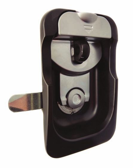
LOCK FOCUS

    Creating Solutions since 1972

9
CABINET AND DRAWER LOCKS
BOLT LOCKS
     Ideal for use on drawers. Available in a wide
     variety of sizes and fixing options.

     FEATURES & SPECIFICATIONS

     • Zinc alloy housing with Bright Chrome finish.
     • Stainless steel capped barrel.
     • Key removable in locked and unlocked positions.
     • Zinc plated steel bolt.
     • Available in round or square face.
     • Pressed steel back plate.
     • Rotating key 180º results in bolt movement.
     • Compatible with 16mm and 19mm boards.
     • Can be used with Bezel, see P. 32.

     QUICK REFERENCE GUIDE

       Lock                                              Key Series               Movement

       19mm Vertical Projection Bolt                     01, 02                   B
       19mm Left Projection Bolt                         01, 02                   B
       19mm Right Projection Bolt                        01, 02                   B
       22mm Vertical Bolt Projection                     01, 02, 07, 08, 17, 18   B
       22mm Left Bolt Projection                         01, 02, 07, 08, 17, 18   B
       22mm Left - Barrel Exchange                       R2, RE, RX, XT           B
       22mm Right Bolt Projection                        01, 02, 07, 08, 17, 18   B
       22mm Right - Barrel Exchange                      R2, RE, RX, XT           B
       C4 Universal Drawer Bolt                          KA, KD                   N/A

11      CABINET AND DRAWER LOCKS
BOLT LOCKS
BOLT TYPES B & C Fixing Details for Bolt LOCKS
.6 27.0
11
.3
37
31.6
37.7
.0
66.6
16
16
.0
ø19.1 Min.
Fixing Details
Note: fixing holes ø20.0
if bezel is used
BOLT TYPE B BOLT TYPE C
BOLT TYPES F & R
16
16 .0
.0
L L
BOLT TYPE FX BOLT TYPE RX
Bolt out of flat Bolt out of round
Call Out code Dimension L
V 19.5
F 21.5
R 28
X 40.5
L 49.5
M 51.5
CABINET AND DRAWER LOCKS 12BOLT LOCKS
Vertical Projection BOLT 19mm & 22mm
2.0 2.0
throw
9.0
Top of 20.8 23.8
16.0
drawer
19.0 22.0
when using
ëRi bolt
ø3.5
28.0
hole
ø19.0
ø19.0
12.5
27.0
5.0 5.0
35.0
19mm 22mm
19mm A/PB1V
22mm* A/PB2V
*Available with barrel exchange
Right/Left Projection BOLT 19mm & 22mm Right/Left
2.0 2.0
20.8 23.8
ø3.5 fixing
holes countersunk Edge of
from rear 19.0 22.0
cupboard
door
ø19.0
ø19.0
27.0
35.0
16.0
9.0 throw
5.0 5.0
12.5 28.0
when using R bolt
19mm Right/Left 22mm Right/Left
19mm Right A/PB1R
19mm Left A/PB1L
22mm Right* A/PB2R
22mm Left* A/PB2L
*Available with barrel exchange
13 CABINET AND DRAWER LOCKSBOLT LOCKS
C4 Universal Drawer Bolt Fixing Details for C4 Bolt
22 5
4.7
20.3
9.6
32.4
37.7
21
11 mm bolt throw
28.1
ø27
50
16.2
32.4
49.8 12.6 30 Fixing hole details
ø4 countersunk hole
from other side
C4 Universal Drawer Bolt I/PBC4
CABINET AND DRAWER LOCKS 14PROJECTION LOCKS
These locks are most suited for cupboards.
FEATURES & SPECIFICATIONS
• Zinc alloy housing with Bright Chrome finish.
• Zinc alloy diecast bolt.
• Key removable in locked and unlocked positions.
• Positive click action mechanism.
• Rotating key 180º results in bolt movement.
• Square Back Bolts suit panels up to 19mm thick.
• Lever Locks suit panels up to 22mm thick.
• Can be used with Bezel, see P. 32.
QUICK REFERENCE GUIDE
Lock Finish Key Series
Square Back Bolt with Vertical Projection Bright Chrome 01, 02, 07, 08, 17, 18
Square Back Bolt with Left Projection Bright Chrome 01, 02, 07, 08, 17, 18
Square Back Bolt with Right Projection Bright Chrome 01, 02, 07, 08, 17, 18
Vertical/ Left/ Right Projection- Barrel Exchange Bright Chrome R2, RX, XT
6mm Lever Lock Natural ZA
22mm Lever Lock Natural ZL
15 CABINET AND DRAWER LOCKSPROJECTION LOCKS
Fixing Details for Square Back Bolt Square Back Bolt*
Edge,s location will change pending locking on the 20.0
left/right / vertical.
35.2
26.0
26.0
ø19.1
40.0
31.0
3.5
10.5
2.5
bolt throw ø4.2
15.5 9.2 countersunk hole 40.0
from other side
31.0
ø19.0
20.0
8.0
Square Back Bolt - Vertical A/PBSV
Square Back Bolt - Right A/PBSR
Square Back Bolt - Left A/PBSL
*Available with barrel exchange
Fixing Details for 6mm/22mm Lever Lock Lever Lock
6.4
43.0 14.3
16.0
Min.
57.2
38.0
66.7
ø15.9
18.3
2 holes ø6.0 6.9
6.4
6mm Lever Lock A/PN06
22mm Lever Lock A/PN22
CABINET AND DRAWER LOCKS 16FILING CABINET LOCKS
Suited to a wide range of filing cabinets. Available in
a number of shapes, movements, fixing methods and
keying. The lock can be fitted in seconds by simply
pushing into panel cut-out.
FEATURES & SPECIFICATIONS
• Zinc alloy housing with Bright Chrome finish.
• Zinc plated steel cam.
• Key removable in locked and unlocked positions.
• Rotating key 180º results in rotary cam movement.
• Stainless steel capped barrel.
• Suits 0.5 - 0.9mm thick panels.
• Available in round and square faces.
• For cam options see P. 86.
QUICK REFERENCE GUIDE
Lock Key Series Fixing Cam Options
19mm - Round Face 01, 02, 07, 08, 17, 18 Z, Y DM, MS, 82, 88
19mm - Square Face 01, 02, 07, 08, 17, 18 Z, Y D4, 82, 88
20mm - Round Face 01, 02, 07, 08, 17, 18 Q, K D4, 82, 85
20mm - Square Face 01, 02, 07, 08, 17, 18 Q, K D4, 82, 85
20mm - Flat Square Face 01, 02, 07, 08, 17, 18 Q, K D4, 88
20mm - Barrel Exchange R2, RE, RX, XT N, Z DM, MS, 82
17 CABINET AND DRAWER LOCKSFILING CABINET LOCKS
Fixing Details for filing Cabinet Locks 19mm
21.7
16.6 Min.
4.3
11.1 throw after
180 rotation
ø19.1 22.2 25.4 Sq.
0.5-0.9 thick panel
(options available) Round Face Square Face
Round Face A/FRX1
Square Face A/FSX1
20mm 20mm Barrel Exchange
7.0 Quick Fix
21.0 21.0 21.0 22.0
ø22.0
0.5 - 0.9 Thick Panel
Round Face Square Face Flat Face
Round Face A/FRX2
Square Face A/FSX2
Flat Square Face A/FNX2 Round Face A/FX--
CABINET AND DRAWER LOCKS 18SPINDLE LOCKS
Suitable for multi-drawer cabinets. Available
in a wide range of shapes, movements, fixing
methods and keying
FEATURES & SPECIFICATIONS
• Zinc alloy housing with Bright Chrome finish.
• Stainless steel capped barrel.
• Key removable in locked and unlocked positions.
• 20mm spindle has double entry key.
• Pressed steel back plate.
• Rotating key 180º results in rotary spindle movement.
• For fixing details see P. 91.
• For movement details see P. 92.
QUICK REFERENCE GUIDE
Lock Key Series Movement Fixing
19mm Spindle Lock 01, 02, 11, 12 B NFR
19mm Spindle Stamlock 01, 02, 11, 12 S NFR
20mm Spindle Lock 07, 08, 17, 18 B NFR
19 CABINET AND DRAWER LOCKSSPINDLE LOCKS
Fixing Details for 19mm & 20mm Spindle Lock 20mm Spindle Lock
28.0 Nut Fix 1.9
16.6 Min. 4.3 7.2 hole depth
6.5 slot depth
7.1
12.3
22.2
View on Barrel
13.0 Max. End
ø19.1 Min.
0.5 - 0.9
thick panel
(options available)
Spindle Lock A/SR20
Nut Fix
13.0 Max.
19mm Spindle Lock 19mm Spindle Lock Slamlock
1.9 19.7 18.0
4.3 12.0
32.0
20.0
22.2 7.1
Round Face View on Barrel
End 13.0 Fixing
Max. nut ø4.2 bracket
fixing holes
(2 places)
50 ± 2
9.0
Spindle Lock A/SR19
Spring clip spreads when
Spindle Lock with Bracket A/SR19 with Bracket slammed or when spindle is
rotated
CABINET AND DRAWER LOCKS 20SPANNER LOCKS
KEY LOCKABLE SPANNER LOCK
4.6 20.0
Suitable for a variety of cabinets and lockers
47.4
20.1
CAM LOCK RUBBER
WASHER
20.1
22.5
CAM FIXING FIXING DETAILS
LOCK SCREW ‘O’ RING 18.0 32.0
FIXING NUT DIMENSIONS
7.0
Key Lockable Spanner lock A/SP18
SPANNER LOCK
FEATURES AND SPECIFICATIONS
• Suitable for a variety of cabinets and lockers.
• Available in a number of unlocking options
including pin and square drive.
• Available in 18mm or 30mm long body.
4.0
18.0 or 30.0
32.0
7F
7mm Female
5P Square 7.0 DIMENSIONS
3P 5mm Pin
DS 3mm Pin
2mm Driver
Slot 20.1
20.1
8T
8D 8mm Triangle
8mm Square
8S 2mm Slot
8mm Square 22.5
7S
7mm Square FIXING DETAILS
18mm Spanner lock A/SR18
30mm Spanner lock A/SR30
21 CABINET AND DRAWER LOCKSCAM LOCKS
CAM LOCKS 11mm - 32mm
     The Lock Focus camlock is suitable to a wide variety of
     applications, ranging from sheet metal doors, drawers &
     office furniture. Camlocks can also be used on wooden
     furniture (thickness dependent).

     FEATURES & SPECIFICATIONS

     • Zinc alloy housing with bright chrome finish.
     • Stainless steel capped barrel.

     • Key removable in locked and unlocked positions
       (B movement only).
     • Key removable in locked position only (S and A
       movements).
     • Master and non-master keying.
     • 90 or 180 degree movement, refer P. 92 (Movement).
     • Clockwise or anti-clockwise movement.

     • Nut fixing, across flats or across rounds clip fixing,
       refer to P. 91 (Fixing).
     • Multiple cams available, refer P. 86 (Cams).

                                                                     MATERIAL COMPATIBILITY

                                                                                      Max. Material Thickness
                                                                                       11mm Camlock        4.0
                                                                                       16mm Camlock        8.0
                                                                                       19mm Camlock        13.0
                                                                                       20mm Camlock        13.0
                                                                                       22mm Camlock        16.0
                                                                      Max. Material
                                                                       Thickness       32mm Camlock        27.0

     QUICK REFERENCE GUIDE

       Cam Lock              Square     Round       Key Series             Movement             Fixing

       11mm                  Y          Y           01-18                  BSAC*                NFR
       16mm                  Y          Y           01-18, CL, FS          BSAC*                NFR
       19mm                  Y          Y           01-18, CL              BSAC*                NFRQK
       20mm                  Y          Y           07,08,17,18            BSAC*                NFRZY
       20mm Barrel Ex        N          Y           R2, RE, RX, XT         BC                   NFRZ
       22mm                  N          Y           01-18, ES              BC                   NW
       32mm                  N          Y           01-18, CL, ES          BC                   NW

                                                                                            *(C=Round face with nut only)

23      CAM LOCKS
CAM LOCKS 11mm - 32mm
INSTALLATION CUT-OUT 11-16mm Camlock 11mm CAM LOCK
16.0 17.2 16.0 16.0
11.2
7.0 Fixing
nut
ø19.1
Fixing Details
11-16mm Camlocks Circlip
ø22.5 24.0 Sq.
4.0 Max
Round Face Square Face
Round Face A/CR11
Square Face A/CS11
16mm CAM LOCK
24.0 16.0 16.0
16.0
7.0
Fixing
Nut
ø22.5 24.0 Sq.
8.0 Max.
Round Face Square Face
Round Face A/CR16
Square Face A/CS16
CAM LOCKS 24CAM LOCKS 11mm - 32mm
INSTALLATION CUT-OUT 19-32mm Camlock 19mm CAM LOCK
16.6 28.0 16.0 16.0
19.8
4.3 Nut
fix
ø19.1
Fixing Details
19-32mm Camlocks
22.2 25.4 Sq.
13.0
Max.
Round Face Square Face
Round Face A/CR19
Square Face A/CS19
Round Face Quick Fix A/CRX1
Square Face Quick Fix A/CSX1
20mm CAM LOCK (SLIM FACE) 20mm BARREL EXCHANGE CAM LOCK
28.0 16.0 16.0 16.0 20.1
7.0
19.8 Fixing
Nut
3.0
Nut
Fix
13.0 ø21.0 21.0 Sq.
Max. ø22.0 13.0
Round Face Square Face
Round Face A/CR20 Round Face A/CX--
Square Face A/CS20
Round Face Quick Fix A/CRX2
Square Face Quick Fix A/CSX2
25 CAM LOCKSCAM LOCKS 11mm - 32mm
22mm CAM LOCK 32mm CAM LOCK
2.0 cam 2.0 cam
thickness 16.0 thickness 16.0
22.3 32.0
4.3
4.3
16.0
Max. ø22.2 27.0
29.9 Max. ø22.2
39.6
Round Face A/CR22 Round Face A/CR32
CAM LOCKS 26FLANGE FIX LOCKS
These locks are best suited for doors and drawers.
Rotating the key results in rotation of either a rotary
cam or 13mm throw.
FEATURES & SPECIFICATIONS
• Zinc alloy diecast housing.
• Zinc alloy diecast cam/throw.
• Key removable in locked and unlocked positions.
• Rotating key 180º results in rotary cam movement.
• Stainless steel capped barrel.
• The lock fits into a 19.1mm diameter hole.
• Suits panels up to 19mm thick.
• Can be used with Bezel, see P. 32.
QUICK REFERENCE GUIDE
Lock Key Series Movement
Back Fix Hor. mount 01, 02, 07, 08, 17, 18 BC
Multi Drawer 01, 02, 07, 08, 17, 18 B
Multi Drawer single flange 01, 02, 07, 08, 17, 18 B
Back Fix Ver. mount 01, 02, 07, 08, 17, 18 B
Back Fix Hor. mount barrel exchange R2, RE, RX, XT B
Back Fix Ver. mount barrel exchange R2, RE, RX, XT B
27 CAM LOCKSFLANGE FIX LOCKS
INSTALLATION INSTRUCTIONS Multi Drawer
32.0 16.0 ø4.5 fixing holes
countersunk from rear
19.0
32.0
ø19.1 Min.
ø19.1 Min.
42.0
Single Flange Mount
Horizontal Mount
44.0
20.0 2.0 flange
thickness
ø6.0
ø19.1 Min.
32.0
ø19.0
6.5
24.0 7.0
64.0
Vertical Mount
Back Fix Horizontal Mount A/CB2D
Back Fix Horizontal Mount Multi Drawer Single Flange
16.0 2.0 cam ø 4.5 fixing hole
thickness countersunk from rear
ø 4.0 fixing 2.0 flange
holes countersunk thickness
from rear
20.0
16.0
19.0
ø19.0
30.8 44.0
20.0 2.0 flange
thickness
32.0 24.0
ø6.0
42.0 31.8
ø19.0
6.5
24.0 7.0
64.0
Back Fix Horizontal Mount A/CB20 Back Fix Horizontal Mount A/CB2S
CAM LOCKS 28FLANGE FIX LOCKS
Multi Drawer Back Fix Vertical Mount Back Fix Vertical Mount - Barrel Exchange
16.0 31.8 34.2
16.0 24.4
22.0
ø19.0
42.0
32.0
32.0
42.0
ø19.0
ø4.0 fixing
holes countersunk 24.0 2.0 cam
from rear thickness ø4.0 fixing
holes countersunk
from rear 26.5 2.0 flange
thickness
Back Fix Vertical Mount A/CB2V Back Fix Vertical Mount A/CB3V
Back Fix Horizontal Mount - Barrel Exchange
16.0
34.2
2.0 flange
ø4.0 fixing thickness
holes countersunk
from rear
24.4
ø19.0
32.0 22.0
26.5
45.0
Back Fix Horizontal Mount A/CB3H
29 CAM LOCKSLATCH LOCKS
Suitable for drawers and doors when no
Locking security required
FEATURES & SPECIFICATIONS
• Zinc alloy die cast knob and housing.
• Zinc plated steel cam.
• Nut fixed.
• Allows movements B S A.
19mm
16mm
Latch Lock 16mm Latch Lock 19mm
16.0 16.6 Min.
Min.
Fixing Details
Fixing Details
ø19.1 Min.
ø19.1 Min. 24.0 19.3 28.0
16.0 22.0 4.3
13.0 18.0 19.8
47.0
ø30.0 8.3 Max.
Fixing
13.0 Nut
Max.
ø7.5
Hole and Slot
Latch Lock 16mm A/L316 Latch Lock 19mm A/L419
CAM LOCKS 30RADIAL PIN TUMBLER
These locks are best suited for doors and drawers.
FEATURES & SPECIFICATIONS
• Zinc alloy diecast housing.
• Rotating the key results in 90º rotary cam movement.
• Zinc plated steel cam.
• Brass Nut fixing.
• Allows movements - S A C.
• Can be fixed by 3mm or 6mm nut.
Radial Pin Tumbler
A 16.2
16.0
B
Min.
6.0
ø19.1 Min. Fixing
Nut ø22.2
C
Fixing Details
QUICK REFERENCE GUIDE
Lock DIM. A DIM. B DIM. C
C-17 26.5 17.0 8.3 max
C-22 31.5 22.0 13.2 max
C-30 38.5 30.0 21.5 max
31 CAM LOCKSACCESSORIES
HAMPER / TAMBOUR DOOR LOCK -
CAMLOCK SPACER - T/SPAC M/CAM P6 AND M/STRK P6
FEATURES & SPECIFICATIONS FEATURES & SPECIFICATIONS
• Used when the position of the lock needs to be • Ideal for use on overhead hampers.
brought forward in relation to the mounting panel.
• Fits into 19.1mm diameter hole.
• Outside diameter 22.2mm.
• Suits panels up to 19mm thick.
• 1.6mm thick steel tube.
• Glass reinforced strike and cam.
• Available in 3mm, 6mm, 7.5mm and 9mm thickness.
• Key removable in locked and unlocked positions.
Varied ø4.5 fixing
Thickness hole countersunk
from rear 28.0
Spacer
12.0 23.0
4.0 Camlock
location
28.0 46.0
56.0
Camlock
Assembly Panel
6.0
CAMLOCK FLAT WASHER - O/CWFL BEZELS
ø34.0 Bezels are designed to fit into the nozzles of our locks.
Their main function is to finish off a drilled hole in timber.
They come in Nickel colour.
ø19.2 8.0
ø25.3
ø19.4
Bezel - 19mm
16.3
ø22.3 6.4
CAMLOCK PRONG WASHER - O/CWPR
ø29.0
ø25.40
ø19.10
Bezel - 22mm
1.8
Size Fixing hole
19mm ø20.0
16.2 22mm ø23.0
CAM LOCKS 32NOTES 33
DOOR HARDWARE
PUSH LOCKS

     Suitable for both timber and aluminium
     furniture

     FEATURES & SPECIFICATIONS

     • Zinc alloy die cast housing and pin.
     • Key removable in locked and unlocked position.
     • Fits in 19mm or 22.1mm diameter hole from rear
       of a panel.

     QUICK REFERENCE GUIDE

       Lock                                      Key Series                          Material    Movement

       12mm throw                                01, 02, 11, 12, 17, 18, RX, XT,R2   Zinc, S/S   N/A
       11mm throw                                01, 02                              Zinc        S
       Pin Projection                            01, 02                              Zinc        B
       PP5 Front/Rear Fix Cover                  N/A                                 Zinc        N/A
       PP5 Front Fix Cover - S/S                 N/A                                 S/S         N/A

35      DOOR HARDWARE
PUSH LOCKS
12mm throw - Zinc
28.8 19.0 40.4
ø4.0
2.0 24.0
ø19.1
50.0
32.0
ø19.1
32.0
ø7.0
M4 x 10 deep
11.6
Locked ø4.0 Fixing holes Unlocked Fixing Details - Zinc/SS
(Pin Extended) countersunk from (Pin Retracted) (rear fix only)
rear
12mm throw - S/S
ø19
50
ø3
.5
9.3
47.6
12mm throw Zinc* A/PP5
12mm throw S/S* A/913213
*Available with barrel exchange
DOOR HARDWARE 36PUSH LOCKS
11mm throw
23.5 22.0
12.0
2.3
ø22.0
50.0
ø22.1
35.0
35.0
ø8.0
Min.
34.8 M4 x 8
deep
11.6
Locked ø4.0 Fixing holes Unlocked
(Pin Extended) countersunk 90º from (Pin Retracted)
rear
11mm throw A/PP2
Projection Pin
ø35.0 Min.
clearance required
Screw 7.5 pin ø22.0 Min.
ø19.1 Min. 16.6 Min.
position throw
ø22.2
ø6.0
ø19.1
18.0 Min.
M4 x 8
deep
37.0 Glass Fixing Wooden Fixing Metal Fixing
Pin
Projection Pin A/PP1 Material Fixing Code
Glass thickness 10mm G3
Glass thickness 8mm G6
Glass thickness 6mm G7
Metal N
Wood P
37 DOOR HARDWAREPUSH LOCKS
PP5 Front/Rear Fix Cover
32
25.8
ø3.20
ø19.6 ø19.6 To suit M3.5
Taptite screw 54.2 ø23.2
Front Fix Cover Rear Fix
PP5 Front Fix Cover D/PP5C
PP5 Rear Fix Cover D/PP5CR
(Screws available on request)
PP5 Front Fix Cover - S/S
ø23
38.30 23
10.50 ø19.50
PP5 Front Fix Cover I/PP5C/SS
DOOR HARDWARE 38CYLINDERS
Best suitable for screen doors
FEATURES & SPECIFICATIONS
• Features two locking barrels that operate central
locking pawl from either side of the door.
• Zinc alloy diecast housing.
• Bright Chrome finish.
• Accessible from both internally and externally.
QUICK REFERENCE GUIDE
Lock Lock Insert / Keying Access Pawl / Tongue Rotation
AD4 03, 27 Double sided 135º
AD6 External Access - 27, 28, Snib Double, Single sided 155º
Internal Access - NL, COM, RES
AD7 External Access - 27, 28, Snib Double, Single sided 155º
Internal Access - NL, COM, RES
AD8 External Access - 27, 28, Snib Double, Single sided 360º
Internal Access - NL, COM, RES
AT1- 4 27 - 9-12, 12-3, 9-12-3,
Fixed
39 DOOR HARDWARECYLINDERS
AD4 & AD6
9.7
46.50
23.25
R15
5.0
ø3.45
H: 1.85mm
32.9
10/32" UNF
THREAD
16.9
7.4
Locked
135° 155°
2.4 1.8
AD4 A/AD4
AD6 A/AD6
AD7
70.0
35.0
5.4
ø3.45
H: 1.85mm
155°
32.9
10/32" UNF 1.8
thread
7.4
AD7 A/AD7
DOOR HARDWARE 40CYLINDERS
AD8
60.0
5.0 9.9
30.0
R15
360º pawl 31.5
32.9 rotation 25.0
11.7 9.8
6.8 10/32 Commercial Snib Residential Snib
ø17.0
UNF thread (protrudes 19mm) (protrudes 19mm)
AD8 A/AD8
AT1-4
The cylinders differ by Locking Tongue Free rotation.
12 12
ø16.8 - Head 48.0 Max. 32 Nom.
ø16.0 - Body 28.2
9 3
23.6
Model AT1 Model AT2
Locking tongue
5.8 x 2 3.8
5.5
12
24.4
9 3
Model AT3 Model AT4
Fixed Tongue
AT A/AT1-4
41 DOOR HARDWAREACCESSORIES and
MULTI-PURPOSE
FLUSH MOUNTING TABS
FEATURES AND SPECIFICATIONS
• Best suited for aluminium hinged and sliding doors
or flush installation of standard mortice lock.
• Supplied as a kit with two plates and fixing screws.
• Designed to suit multiple door thicknesses.
• Zinc alloy diecast.
35
5 25
15
M5
6.5
5
Flush mounting tabs A/915209
SECURITY CYLINDER TRIM
FEATURES AND SPECIFICATIONS
• A heavy duty trim for security cylinders where the
cylinder protrudes beyond the face of the door.
• Zinc diecast escutcheon and reinforcing plate.
28.0
ø5.0
58.0 42.0
ESCUTCHEON
REINFORCING PLATE M5 SCREWS
Security Cylinder Trim A/TRIM
DOOR HARDWARE 42ACCESSORIES and
MULTI-PURPOSE
PATIO BOLT
FEATURES AND SPECIFICATIONS
• Best suited for aluminium and timber sliding or hinged
doors.
• 10mm S/S locking bolt available in 50mm (standard)
and 80mm (extended) length.
• Zinc diecast body available in black or white.
• Reversible design allows for left or right hand mounting.
• Compatible with standard barrels, Lock Focus universal
C4 barrel, and one key solution.
157.0
(80mm available)
14.0
50.0
27.0
Keeper Ferrules
(hinged doors) (sliding doors,
x 2 for venting)
Patio Bolt A/913225
43 DOOR HARDWAREACCESSORIES and
MULTI-PURPOSE
EUCLID200
FEATURES AND SPECIFICATIONS
• Twin 6mm locking hooks.
• Surface mounted (concealed screw fixing).
• Spacers allow for adjustment of lock body.
• Large D handle for ease of opening sliding doors.
• Internal latch slide for easy latching.
• Anti-slam pin prevents damage of locking hooks.
• Non-handed design.
• Solid diecast zinc construction.
• Available in matt black.
• Available in 27 series and C4 with locking and non-
locking external handle.
Euclid200 A/915121
DOOR HARDWARE 44NOTES 45
GARAGE ROLLER DOOR LOCKS
GARAGE ROLLER DOOR LOCKS
     The Lock Focus garage roller door lock range has a spread of
     capabilities that enable different retrofit abilities, low profile
     features, pin cylinder options and the addition of a grip recess.

     FEATURES & SPECIFICATIONS

     • Locking arms have a 19mm stroke on all roller door
       products.
     • Zinc diecast body and fascia with galvanised steel arms
       (except V7).

     • The V7 roller door lock is a cost effective solution with
       engineering plastic housing and galvanised steel arms.

     • Key removable in horizontal position only, this allows
       for the operation of an internal override.

     • V2, V9, V9C4 & V9LP product ranges can be configured
       with an internal deadlocking feature (i.e. cannot be
       opened from the inside).
                                                                     ARM LENGTHS

                                                                       STD                       259mm
                                                                       EXT                       336mm
                                                                       EXTV5                     357mm

                                                                                                  259.0
                                                                                               Arm Length

     QUICK REFERENCE GUIDE

      Roller Door Lock      Fascia        Key Series                Internal Latch                          Arm Options

      V1                    Y             19                        Flush, Finger Grip                      STD
      V2                    N             19, 20                    Flush, Finger Grip, Key                 STD, EXT
      V3 8mm Square         T Handle      N/A                       N/A                                     STD
      V4                    Y             19                        Flush, Finger Grip                      STD, EXT
      V5                    Y             19                        Plastic Dial                            EXTV5
      V7                    N             19, 23, 25, CL            Plastic Dial, With/Without Hole         STD, EXT
      V9                    N             23, 25, CL                Plastic Dial, Metal Grip                STD, EXT
      V9C4 + V9LP           Y             5-Pin LF 001 or Bi Lock   Standard Metal Grip                     STD

47      GARAGE ROLLER DOOR LOCKS
GARAGE ROLLER DOOR LOCKS
INTERNAL LATCH OVERRIDE V9C4 & V9LP FREELATCH VS DEADLOCKING
• Flush latch and finger grip latch available on FREE LATCHING FUNCTION
V1, V2, V4
Barrel Driver
ø39.0 54.0
7.0
Flush Latch (3) 15.5
Finger Grip Latch (6)
Latch Drive Lug Triangle
• Plastic turn grip A & B available on V5, V7, V9 Barrel Lever
Drive Lug
ø45.0 ø45.0
Cylinder Bible
Plastic Turn Grip Plastic with Key Hole
(A) (B)
• Free latching/dead locking internal latch available DEADLOCKING FUNCTION
on V9C4, V9LP
6.0 ø30.9
Circle
Latch Drive Lug
Internal Latch Override Barrel Lever
Drive Lug
• Alternative latch on V9
Cylinder Bible
ø31.0
Barrel Lever
Drive Lug
Metal Latch (G)
GARAGE ROLLER DOOR LOCKS 48GARAGE ROLLER DOOR LOCKS
V1
8.4
7.1
ø9.5 ø20.0
58.5
45.0
15.3 76.0
146.0
Side view Fixing Details
External Fascia (lock and fascia)
10.0 19.0
throw
20.0
41.0
16.0
13.0
ø3.2
106.5
259.0
Front view with fascia removed
V1 A/V1PB
V2
22.6
104.7
7.7
10.0 ø9.0 ø19.1
20.0
ø19.0
16.0
13.0
40.5
54.0
19.0
ø3.2 throw
259.0 (arms extended)
7.9 76.0
Fixing Details
V2 A/V2
49 GARAGE ROLLER DOOR LOCKSGARAGE ROLLER DOOR LOCKS
V3
10.0 19.0 ø15.5 For use
throw ø9.5 with escutcheon
20.0 41.0
16.0
13.0
ø3.2
ø13.0 For use
106.5 76.0 without escutcheon
259.0
Fixing Details
Front view (internal)
V3 A/V3
V4
254.0
85.0 78.0 pocket
95.0 CL Barrel
85.0 ø12.0 78.0 pocket
27.2 Min.
34.0
124.0 123.0
Fixing Details
External Fascia
8.0
8.0 19.0
10.0
throw
20.0
40.5
16.0
13.0
ø3.2
15.5 105.0
Side view 259.0
(lock and fascia)
V4 A/V4
GARAGE ROLLER DOOR LOCKS 50GARAGE ROLLER DOOR LOCKS
V5
130.0 POCKET 76.0
135.0
ø9.5 38.0 38.0
36.9 32.0
ø20.0 180.0
269.0 FIXING DETAILS
FRONT VIEW
6.4
19.0
7.0 THROW 46.0
13.5
16.5 90.7
319.0 (ARMS EXTENDED)
SIDE VIEW
FRONT VIEW WITH FASCIA REMOVED
V5 A/V5
V7
81.9
41.4 19.0
20.0 throw ø9.5 ø19.1
16.0 13.0 ø17.8 41.9
ø3.2
8.0
76.0
258.2 16.4
Fixing Details
V7 A/V7
51 GARAGE ROLLER DOOR LOCKSGARAGE ROLLER DOOR LOCKS
V9
19.0 105.1
throw
ø9.5 ø19.1
10.0
ø19.0
16.0
13.0
41.0
ø3.2 20.0
76.0
260.0 8.5
Fixing Details
16.7
Side view
V9C4
105.1 7.4 76.0
28.0 13.8
ø9.0
38.0
6.0 ø22.0
18.5
V9LP
105.1
76.0
28.0 7.5
ø9.0
18.5 38.0
6.0 ø22.0
V9 A/V9
V9C4 A/V9C4
V9LP A/V9LP
GARAGE ROLLER DOOR LOCKS 52NOTES 53
HANDLES
FLUSH HANDLES

     Suited for sheetmetal doors requiring 3-point
     locking (0.6-1.8mm sheet thickness)

     FEATURES & SPECIFICATIONS

     • Locking consists of flush pan with inset rotational
       handle grip or pad-lockable.
     • Handle grip rotates 90º to lock/unlock 3 point
       locking cam and rods.
     • Plastic pans snap fit into cut-out, metal pans use
       retention clip to resist tampering.
     • Pan available in plastic or zinc diecast.
     • Handle grip constructed from engineered plastic for
       flush locking and diecast zinc for pad lockable version.
     • Pad lockable lock suits padlocks up to 7mm shackle.
     • The cam can be mounted on left or right edge.

     • Standard keying, barrel exchange, and C4 keying
       available.
     • For Cam options refer to P. 86.

     QUICK REFERENCE GUIDE

       Lock                                        Key Series                           Colour   Cam

       Plastic Pan                                 NL, 01, 02, 11, 12, 17, 18, CL       Black    F1, F2, F3
       Metal Pan*                                  NL, 01, 02, 17, 18, R2, RE, RX, XT   Black    F1, F2, F3
                                                                                        Silver

       C4 Metal Pan                                KA, KD                               Black    F1, F3
       Pad Lockable                                N/A                                  Black    F1, F2
     *Available with barrel exchange

55      HANDLES
FLUSH HANDLES
INSTALLATION INSTRUCTIONS Plastic/Metal Pan
• For vertical mounting locking and non-locking versions. DIM A*
• For right and left door edge mounting (left edge shown here). 27.5
65.0
6.5 *DIM A = 19.5+CAM BEND (B1)
26.0 72.0
93.60
Grip centre 52.10
106.0
Left Mount
Installation Cut-Out shown 57.0
1. Snap Fit Lock In Door (internal view)
C4 Pan
A. Rotate cam into position as
shown to fit through cutout
B. Snap legs of lock
must rest inside on
edge of cutout
C. Push lock firmly in Plastic Pan A/HF1
and down to install lock
Metal Pan* A/HF2
C4 Pan A/HFC4
*Available with barrel exchange
2. Fit Locking Bars (internal view)
Pad Lockable - Heavy Duty Latch Lock
E. Rotate retainer 7.3
in direction of 21.5
arrows to secure
locking bars
125
80
D. Fit locking bars
to cam lugs
Pad Lockable I/HDLL
HANDLES 56SWING HANDLES
Best suited for sheet metal furniture of various
thicknesses
FEATURES & SPECIFICATIONS
• 8mm square drive spindle available in standard length
and with extension adaptors.
For swing handles suitable for sheet up to 3mm thick:
• Spring loaded handle indicates when unlocked.
• Changeable locking inserts.
• Suits large range of cam types - flat, bent and 3-point cams.
• IP66 rating.
For swing handles suitable for sheet up to 10mm thick:
• Extended spindle allows for adjustable cam types and
is suitable for 3-point mechanisms.
• 3 padlocking handles available suitable with padlock
with up to 13mm thick.
QUICK REFERENCE GUIDE
LOCK LOCK INSERT/ KEYING MATERIAL FINISH HANDLE ROTATION
HS741 Wafer, CL, C4, ETSA Zinc diecast Black 90º rotatable handle
S/S Chrome
HS742 BiLock Zinc diecast Black 90º rotatable handle
S/S Chrome
HS743 Padlockable Zinc diecast Black 90º rotatable handle
S/S Chrome
HS744 ASSA Compatible Zinc diecast Black 90º rotatable handle
Chrome
F736/F737 Padlockable Zinc diecast Chrome 360º rotatable handle
F738 CL001, L003, ETSA Zinc diecast Chrome 360º rotatable handle
HSS Padlockable S/S 360º rotatable handle
57 HANDLESSWING HANDLES
INSTALLATION INSTRUCTIONS F736-F737
Mounting back plate
HS741- HS742 20
35
68
34 20
Fixing 18
screws
150
80 80
143
25
Padlockable Insert 39 39
Installation
Cut-Out Swing Handle Body
Short Spindle - F736/HSS-/3A Extended Spindle - F737/HSS-/2A
F736-F738, HSS ø23.0
20.0
F736 I/F736
80.0 F737 I/F737
Fixing Details
*for sheet thickness > 3mm, use 20mm hole HSS Extended Spindle I/HSS-/2A
HSS Short Spindle I/HSS-/3A
ø9.00
(0.8-3mm sheet*)
HS741- HS744 F738
17 34 19.6
36.0 16.0 68.6
95 80
143
165.0 108
23.5
32
32.4
Front View Side View
HS741 A/IF741 F738 I/F738
HS742 A/IF742
HS743 A/IF743
HS744 A/IF744
HANDLES 58T & L HANDLES
The Lock Focus T&L Handle range is suitable
for use on garage and shed doors, also sheet
metal furniture.
FEATURES & SPECIFICATIONS
• Key locking handle with 8mm square drive for
operation of locking cam.
• Rear fix option (R) mounted tapped holes concealed
underneath rose.
• Front fix option (F) fitted from front of the rose.
• Diecast zinc handle and rose.
• Bright Chrome finish.
• 90 or 180 degree movement available. See P. 92.
• Available with spindles and cams. For cams see P. 86.
• The padlocking version suits shackles up to 9.5mm
diameter.
QUICK REFERENCE GUIDE
HANDLE KEY SERIES MOVEMENT
Large T Handle --, 01, 02, 11, 12, CL, FS, ES BSAC
Small T Handle 01, 02, 11, 12, CL, FS BSAC
Lever Handle --, 01, 02, 11, 12, CL, FS BSAC
Lever Handle - Padlocking 01, 02, 11, 12, CL, FS SA
Lever Handle - Keyable/ Padlocking 01, 02, 11, 12, CL, FS SA
Lever Handle - Pin Cylinder KA, KD B
T Handle - Pin Cylinder KA, KD B
59 HANDLEST & L HANDLES
ASSEMBLY INSTRUCTIONS ASSEMBLY
1. Assemble handle to rose and rotate clockwise over • Assembly applies to T and L handles
1/4 turn.
2. Assemble detent bush locating over lug on handle shaft. SPINDLE
3. Assemble spindle to retainer plate by inserting into
centre hole and moving spindle sideways to locate in groove.
4. Assemble retainer plate/spindle to handle/rose by inserting
spindle into square hole in detent bush and locating
retainer plate in rose, with location hole aligned with boss.
5. Insert screw into one of the three holes to suit movement RETAINER
PLATE SCREW
required (A, B, or C/S) and tighten a maximum torque S/M3CS/16/1-/TT
of 1.0Nm.
6. Check function and assemble barrel to handle as required.
ROSE DETENT
(FRONT FIX) LOCATION BUSH
HOLE & BOSS
ROSE
(REAR FIX)
SPINDLES
TYPE CODE LENGTH PLAIN THREADED
B 32mm T/SPIN/B2
HANDLE
L 32mm T/SPIN/L2
M 40mm T/SPIN/M2
C 44mm T/SPIN/C2
D 50mm T/SPIN/D2
T 50mm T/SPIN/T2
BARREL
N 62mm T/SPIN/N2
E 75mm T/SPIN/E2
H 100mm T/SPIN/H2
F 136mm T/SPIN/P2
FIT SCREW HERE FOR
90º ANTICLOCKWISE
TO UNLOCK
FIT SCREW HERE
48 (T2 & N2) FOR 180º
29 (L2)
Length 'L' MOUNTING
FACE
FIT SCREW HERE
PLAIN THREADED KEY LOCKABLE FOR 90º CLOCKWISE
SPINDLES SPINDLES IN ALL POSITIONS TO UNLOCK
HANDLES 60T & L HANDLES
CAMS, SPINDLES AND ROTATION
3-POINT LOCKING CAMS
• Designed to be used with spindle type Q (see image for Spindle Type Q
details). Circlip
• Cams available in flat or stepped. See table below for
Flat Cam
dimensional options.
• Designed to be used with locking rods when required. ø5 X 7 Long Post
To do this: remove split pin and take off saddle, fit
Saddle
locking bars, refit saddle, feed split pin through hole in
the spindle, spread pin legs to secure.
Screw
DIM B DIM C
TYPE CODE END DETAIL DIM L (FLAT) (STEPPED)
71 FLAT 37 10.0
16.0
72 FLAT 65 10.0
73 CAULKED 63.5 13.2
74 CAULKED 57.5 19.5 3.0 16.0
L
75 CAULKED 54.5 22.7
76 CAULKED 51 26.0
35.0 Caulk Detail
(Stepped Cam Only)
45.0
Spindle Type Q and 3-Point Locking Cams
Spindle type Q is designed to be used with a range of
3-point locking cams (refer to table). B
C
2.0
The 3-point locking cam has two versions: a flat cam and
a stepped cam. The flat cams are spaced at 10mm from
the base of the lock. The stepped cams are spaced at
18.0
13.2mm to 26mm from the base of the lock, depending
on the type.
2.0
The 3-point locking cam is designed to be used with
locking rods. To fit the locking rods, the saddle must be
18.8 18.8
removed. To do this, remove the split pin and take off the
saddle. Fit the locking bars, then refit the saddle. Feed Flat Cam Stepped Cam
the split pin through the hole in the spindle, then spread
the pin legs. (not to scale, measurements in mm)
SPINDLE CAM DIM L DIM B DIM C END
TYPE TYPE (FLAT) (STEPPED) DETAIL
Q 71 37 10.0 FLAT
Q 72 65 10.0 FLAT
Q 73 63.5 13.2 CAULKED
Q 74 57.5 19.5 CAULKED
Q 75 54.5 22.7 CAULKED
Q 76 51 26.0 CAULKED
61 HANDLESYou can also read