ADBLUE TUFFA - Installation, Operation and Servicing Manual Version 2.0.0 - Tuffa Tanks
←
→
Page content transcription
If your browser does not render page correctly, please read the page content below
Installation, Operation and Servicing Manual Version 2.0.0

Models:

1350SLBFSAD | 2500HBFSAD | 3500VBFSAD | 6000VBFSAD | 10000VBFSAD | 15000VBFSAD

TUFFA
ADBLUE®
STATIONS
CONTENTS PAGE

1.
   Introduction								2
2.
   Conditions of use 							2
3.
   Safety									3

4.
   Product description							4
		 4.1 Product identification 					4
		 4.2 Product specification						5
		 4.3 Product dimensions							6

5.
   Transport & storage 							9

6.
   Installation & commissioning 					10
   6.1   Installation guidelines 						 10
		 6.2 System installation 							10
		 6.3 System location         						10
		 6.4 Electrical requirements						11
		 6.5 Electrical wiring diagram 						11

7. Operation of the system						                         13
		 7.1 Using the system 						13
		 7.2 Summary of main parts 1350 / 2500 				13
		 7.3 Summary of main parts 3500 / 6000 / 10000 / 15000 15
		 7.4 Filling AdBlue® Station  					17
		 7.5 Dispensing AdBlue® into vehicle 				17
   7.6 Equipment components 					18

8. Maintenance of the TUFFA TANKS				        35
		 8.1 System maintenance tasks						35
		 8.2 Inspection by competent person					36
		 8.3 Internal examination and cleaning					36
		 8.4 Troubleshooting 							37
   8.5 Tank maintenance record						41
		 8.4 AdBlue® delivery log							43

9.
    Warranty									45
10. Contact									46
11. Guarantee registration						46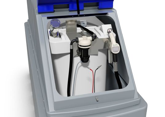
1. INTRODUCTION |              2. CONDITIONS OF USE

1. Introduction

This manual contains specific instructions and information relating to the installation,
operation and maintenance of Tuffa Tanks systems.

2. Conditions of use

    • Read this manual before installing this system.

    • Tuffa Tanks accepts no liability for personal injury or property damage resulting from
    working on or adjusting the equipment incorrectly or without authorisation.

    • Tuffa Tanks accepts no liability for direct, indirect, incidental, special, or
    consequential damages resulting from failure to follow any warnings, instructions, and
    procedures set out in this manual.

    • Tuffa Tanks reserves the right to change the specifications of its products or the
    information in this manual without necessarily notifying its users.

    • Variations in installation and operating conditions may affect the Tuffa Tank systems
    performance. Tuffa Tanks makes no representations or warranties concerning the
    performance of the tank system under the operating conditions prevailing at the
    installation.

    • Only parts supplied by or approved by Tuffa Tanks must be used and no
    unauthorised modifications to the hardware or software should be made. The use of
    non-approved parts or modifications will void all warranties and approvals and could
    lead to hazardous safety conditions.

    • Unless otherwise noted, references to brand names, product names, or trademarks
    constitute the intellectual property of the owner thereof.

                                                                                               2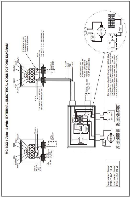
3. SAFETY

3. Safety

PLEASE READ THIS MANUAL CAREFULLY BEFORE USE & COMPLY WITH ALL
INSTRUCTIONS BELOW.

THIS MANUAL SHOULD BE KEPT WITH THE EQUIPMENT AT ALL TIMES.

   1. The major hazard involved with installing and operating the unit is electrical shock.
   This hazard can be avoided if you adhere to the procedures in this manual and exercise
   all due care.

   2. Installation and use of this product should only be carried out by properly trained and
   approved personnel.

   3. Please refer to storage media MSDS which should be supplied by the proprietor of this
   system which will detail the PPE required for handling and emergency procedures.

   4. The user of this product is responsible for the safe and correct use of this product.

   5. This product is only suitable for storage and/or dispensing of the liquid media refer-
   enced at the point of sale.

                                                                                                3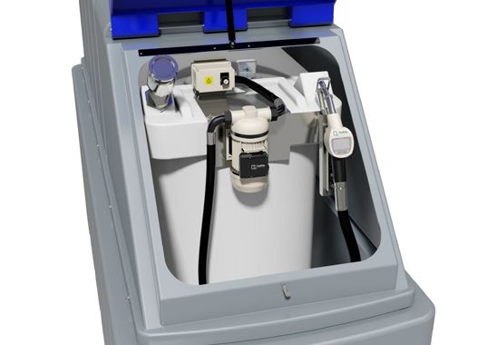
4. PRODUCT DESCRIPTION

4. Product description

Tuffa AdBlue® Stations are designed solely for storage and dispensing of AdBlue®.
The static bunded systems enable safe AdBlue® storage and dispensing in an outdoor
environment. The high standard of specification ensures optimum safety and functionality.
This product’s standard specification is not approved for the resale of AdBlue®.

4.1    Product identification

The identification plate is located within the cabinet of each system and will detail the
capacity, serial number, model number and year of manufacture.

                                                                               If a fuel spill occurs:
          Technical Details                                          • Observe safety precautions (e.g. no smoking)
                                                                     • Stop the fuel from entering drains or
                                                                       watercourses by containing it with sand or
         Model                                                         earth
                                                                     • Do not spread the fuel by hosing it down. Do
         Capacity                                                      not add detergents.
                                                                     • Call the Environment Agency (24 hours)
         Date of manufacture                                                        EMERGENCY HOTLINE
                                                                                       0800 80 70 60
         Serial number
                                                                                   TUFFA TANK SERVICE HISTORY
         Stored product                                                     Date                      Signature

         Weight
         Material                  LLDPE
         Minimum wall thickness    5.4 mm
         Bunded                    Yes      |    No
         Fire protection rating    N/A | 30 min | 60 min
         Quality check

         UKAS Testing Number: 0402 | Issued: 2009 | EN 13341

                      SCAN         Tuffa UK Ltd

                      FOR
                                   Dovefields Industrial Estate
                                   Derby Road, Uttoxeter

                      USER
                                   Staffordshire, ST14 8SW
                                   Tel: +44 (0) 1889 567700       Assured

                      MANUAL
                                   www.tuffa.co.uk

                                                                                                                      4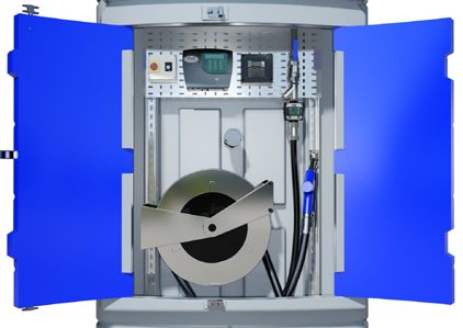
4.PRODUCT DESCRIPTION

4.2 Product specification

                   1350SLBFS       2500HBFS      3500VBFS      6000VBFS       10000VBFS      15000VBFS
                   AdBlue®         AdBlue®       AdBlue®       AdBlue®        AdBlue®        AdBlue®
Capacity           1350 litres     2500 litres   3500 litres   6000 litres    10000 litres   15000 litres
Length             2680mm          2840mm        -             -              -              -
Width              870mm           1520mm        -             -              -              -
Diameter           -               -             2013mm        2550mm         2890mm         2890mm
Height             1665mm          1630mm        2520mm        2585mm         2590mm         3500mm
Cabinet depth      -               -             600mm         600mm          600mm          600mm
Weight (approx.)   210kgs          280kgs        350kgs        430kgs         500kgs         700kgs
Bund material      Lower Linear Density Polyethylene
Inner tank
                   Lower Linear Density Polyethylene
material
Description        Bunded AdBlue® Fuel Station
Fill point         2” stainless steel dry break coupling
Ventilation        1x 3” screened vent
Flow rate          40 lpm (approximately)
Flowmeter          Digital battery operated turbine meter (accuracy +/- 1%)
Delivery hose      6 metres
Hose reel                                        Hose reel available
                   N/A
(optional)                                       8 metres - 19mm bore
Nozzle             Automatic shut off nozzle
Gauge              Clock gauge                   FMS gauge and bund alarm (230V)

                                                                                                            5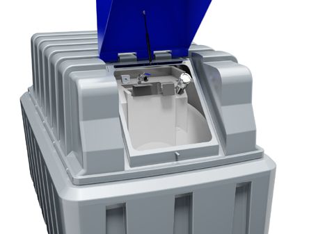
4. PRODUCT DESCRIPTION

                4.3               Product dimensions

        6       1350SLBFS AdBlue®
                          5                              4        3                                     2                                             1

D                                                                                                                                                                  D

                                               2680 mm

C                                                                                                                                                                  C

                                                                                       870 mm
                  1665 mm

B                                                                                                                                                                  B

A               2500HBFS AdBlue®                                 DESIGNED BY     CHECKED BY   APPROVED BY      DATE MATERIAL      DATE
                                                                                                                                                                   A
            6                              5                 4     3 Smith
                                                                 Rob             J Shenton    J Shenton 2 11/06/2020 LLDPE        10/06/2020        1
                                                                                                                              1350 BUNDED
                                                                                                                                                ISSUE      SHEET
                                                                                                                                                  D        1/1
        6                              5       2840 mm   4        3                                     2                                             1
    D                                                                                                                                                              D

    C                                                                                                                                                              C

                                                                               1520 mm

    B                                                                                                                                                              B
                        1630 mm

    A                                                            DESIGNED BY     CHECKED BY   APPROVED BY     DATE MATERIAL       DATE
                                                                                                                                                                   A
                                                                 Rob Smith       J Shenton    J Shenton 11/06/2020 LLDPE          10/06/2020

                                                                                                                             2500 BUNDED

                                                                                                                                                                       6
                                                                                                                                               ISSUE      SHEET
                                                                                                                                                D         1/1
            6                              5                 4     3                                   2                                            1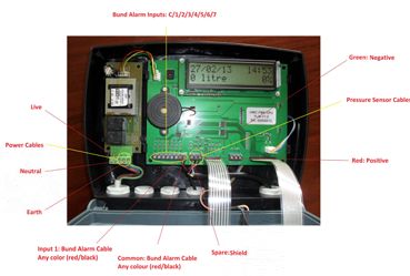
4.PRODUCT DESCRIPTION

3500VBFS
    6    AdBlue®5                                      4                   3                                             2                                              1

D                                                                                                                                                                                              D
                    2013
                         mm

C                                                                                                                                                                                              C

                                            1200 mm
                                                                                              2613 mm

B                                                                                                                                                                                              B
                          2520 mm

                                                               2000 mm

A                                                                         DESIGNED BY         CHECKED BY        APPROVED BY       DATE MATERIAL       DATE
                                                                                                                                                                                               A
                                                                          Rob Smith           J Shenton         J Shenton 11/06/2020 LLDPE            10/06/2020

6000VBFS AdBlue®                                                                                                                   3500 BUNDED WITH CABINET
                                                                                                                                                                   ISSUE            SHEET
                                                                                                                                                                    D               1/1
        6   6                       5   5              4   4               3     3                                       2 2                                            1 1

    D           2550                                                                                                                                                                               D
                     mm

    C                                                                                                                                                                                              C

                                             1200 mm

                                                                                                   3150 mm

    B                                                                                                                                                                                              B
                2585 mm

                                                                2000 mm

    A                                                                           DESIGNED BY        CHECKED BY       APPROVED BY       DATE MATERIAL      DATE
                                                                                                                                                                                                   A
                                                                                Rob Smith          J Shenton        J Shenton 21/10/2020 LLDPE           21/10/2020

                                                                                                                                       6000 BUNDED WITH CABINET
                                                                                                                                                                        ISSUE          SHEET
                                                                                                                                                                            E         1/1
            6                           5                  4                     3                                            2                                                 1
                                                                                                                                                                                                       7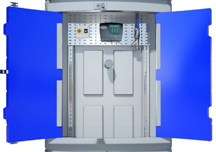
4. PRODUCT DESCRIPTION

10000VBFS AdBlue®
       6                     5                4                         3                                            2                                           1

D                                                                                                                                                                             D
            2890
                 mm

C                                                                                                                                                                                 C

                                    1200 mm
                                                                                            3490 mm

B                                                                                                                                                                                 B
                   2590 mm

                                                            2000 mm

A                                                                     DESIGNED BY         CHECKED BY    APPROVED BY       DATE MATERIAL    DATE
                                                                                                                                                                              A
                                                                      Rob Smith           J Shenton     J Shenton 11/06/2020 LLDPE         10/06/2020

15000VBFS AdBlue®                                                                                                          10000 BUNDED WITH CABINET
                                                                                                                                                        ISSUE         SHEET
                                                                                                                                                                      1/1
       6                     5                4                        3                                        2                                           1D
       6                     5                4                         3                                        2                                               1

D                                                                                                                                                                             D
           2890 m
                 m

C                                                                                                                                                                             C
                                 1200 mm
                                                                                    3460 mm

B                                                                                                                                                                             B
              3500 mm

                                                  2000 mm

A                                                                     DESIGNED BY        CHECKED BY    APPROVED BY       DATE MATERIAL    DATE
                                                                                                                                                                              A
                                                                      Rob Smith          J Shenton     J Shenton 11/06/2020 LLDPE         10/06/2020

                                                                                                                         15000 BUNDED WITH CABINET
                                                                                                                                                       ISSUE         SHEET
                                                                                                                                                        D            1/1
       6                     5                4                        3                                        2                                           1
                                                                                                                                                                                      8
5. TRANSPORT & STORAGE
5. Transport & storage
DO NOT TRANSPORT WITH LIQUID INSIDE THE TANK
1. During transportation the flip lid and cabinet doors are secured by 1 x R clip. The R
clip must be installed prior to transportation.
2. Loading and off-loading must be carried out by a competent person using suitable
rated and maintained equipment, either a forklift with extended forks/tines or a crane. If lifting
slings are used, they must be attached to the lifting points as shown in the pictures below
using a steel lifting eye insert. If lifting from below use a suitable rated forklift with extended
forks. If lifting from above use a suitable rating lifting slings / chains.
3. 1350SLBFSAD / 2500HBFSAD - Lift with main lifting eye highlighted in red in the
image below or forklift from the side.
4. 3500VBFSAD / 6000VBFSAD / 10000VBFSAD / 15000VBFSAD - Lift with x4 equal
spaced lifting brackets as highlighted in red in the image below or forklift from one side using
a ratchet strap to secure the tank to the forklift mast.
5. Tuffa AdBlue® Stations must never be pushed or rolled.
6. During transport and storage, the flip lid or cabinet doors must be closed and secured.
7. Loading, transport and storage areas must be smooth and free of sharp edges.
96. INSTALLATION & COMMISSIONING
6. Installation & commissioning
6.1 Installation guidelines
The proprietor of the Tuffa AdBlue® Station is responsible for complying with all legal require-
ments relating to the installation and use of this product, as well as the guidelines issued by
local firefighting authorities and environmental authorities.
Once the Tuffa AdBlue® Station has been received on site, check that no damage has oc-
curred while in transit. Locate the tank in the desired location using either crane, forklift or
rollers.
6.2 System installation
System foundation
The system must be installed and fully supported on a smooth levelled concrete base built in
accordance with good building standards and engineering principles. It is recommended that
tanks be installed on a concrete base at least 100mm thick. Please refer to diagram below:
6.3 System location
The location of the system should be positioned by a road or passing with sufficient width,
and loading capacity to accommodate a tanker delivering AdBlue®. Provision for the U-turn of
a tanker should be considered. Potential obstacles in the form of tree branches, high voltage
lines, or parked vehicles must be minimized.
The space around the system should allow free and collision-free movement of served vehi-
cles.
Provision should be made to protect tank from impact damage.
106. INSTALLATION & COMMISSIONING
6.4 Electrical requirements
Only a suitably qualified electrician according to applicable regulations may work on the
electric wiring installation. The system components under service, maintenance, and repair
work must be disconnected from the power supply before any work in undertaken.
System power requirements:
230V
• 220 - 240 Volts, 50 Hz +/- 10%
• 20 amp circuit breaker recommended
• Power cable recommendation: 3 Core 2.5mm flex cable
• Duty cycle: 20 minutes
• CAUTION: DO NOT RUN PUMP MOTOR WITH A CLOSED NOZZLE FOR MORE
THAN 2 MINUTES
12V/24V
• Cable clips come pre-wired
• Duty cycle: 20 minutes
• CAUTION: DO NOT RUN PUMP MOTOR WITH A CLOSED NOZZLE FOR MORE
THAN 2 MINUTES
6.5 Electrical wiring diagram (230V)
6.5.1 1350SLBFS AdBlue® / 2500HBFS AdBlue® – Key Switch
PUMP SWITCH
MCB1 6A
PUMP
2 13/05/2019 ISOLATOR REMOVED MB SDN Dunford & Pearson SCHEMATIC
11
XXX XXX XXXXXXXX TUFFA TANKS 14/12/2016 NTS ST/WPS 2 1 of 16. INSTALLATION & COMMISSIONING
6.5.2 3500VBFS AdBlue® / 6000VBFS AdBlue® / 10000VBFS AdBlue® /
15000VBFS AdBlue® – Key Switch
PUMP SWITCH
MCB1 6A
1L1
2T1
ISOL 16A
5L3
6T3
PUMP
MCB2 2A
GAUGE
3C X 0.5 @ 1MTR LONG
X XX/XX/XX XXXX MB SDN Dunford & Pearson PANEL LAYOUT
XXX XXX XXXXXXXX TUFFA TANKS 14/12/2016 NTS LT/WPS 1 1 of 1
127. OPERATION OF THE SYSTEM
7. Operation of the system
The system and its components are intended for AdBlue® only and for the purposes de-
scribed below. Use of this system in a means other than described below is regarded as
mis-use of the system, the user of the system will be liable for any defects that occur due to
its unintended use.
7.1 Using the system
The operation and maintenance personnel must be suitably trained to use the system, the
user must make sure they fully understand the operation and maintenance sections of this
manual.
7.2 Summary of main parts 1350 / 2500
(230V)
Mains Power
Control Panel
Clock Gauge
Suction Hose
Dry Break
Fill Point
Automatic Nozzle
With Built-In
Flowmeter
External
Delivery Hose
Pump
136. INSTALLATION & COMMISSIONING
(230V, pulsemeter)
Mains Power
Control Panel
Clock Gauge
Dry Break Suction Hose
Fill Point
Automatic Nozzle
Pulsemeter Pulsemeter
Remote Display
Delivery Hose
External
Pump
(12V/24V)
Clock Gauge
Suction Hose
Dry Break
Fill Point
Automatic Nozzle
With Built-In
Flowmeter
External Delivery Hose
Pump
Battery
Cable Clips
147. OPERATION OF THE SYSTEM
(1” top suction)
Clock Gauge
Outlet
Isolation Fill Point
Valve
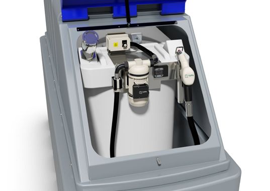
7.3 Summary of main parts 3500 / 6000 / 10000 / 15000 (230V)
Fuel Management System (if selected)
Level Gauge & Isolation
Tank Alarm Valve
Y-Filter
Mains
Junction
Box Flow Meter /
Pulse Meter
Fill Point
Nozzle
Hosereel Hose
(if selected)
156. INSTALLATION & COMMISSIONING
(Terminating in cabinet)
Level Gauge & Isolation
Tank Alarm Valve
Y-Filter
Mains
Junction
Box
Fill Point
167. OPERATION OF THE SYSTEM
7.4 Filling AdBlue® Station
1. Filling should be performed only under constant supervision of an authorised person.
2. This tank can only be filled by a tanker equipped with a 2” female dry break coupling.
3. On 3500 / 6000 / 10000 / 15000 models before filling the tank with AdBlue®, please
check the level of the tank and make note of the tank level before filling and ensure the
high level alarm indicator functions correctly.
4. Fit tanker delivery hose to 2” dry break fill coupling on tank.
5. Engage tanker pump and begin to fill. Stop filling when desired amount has been
dispensed into tank, or when high-level alarm sounds.
6. During the tanker fill always observe tank level gauge throughout the duration of the
filling process. The tanker driver must observe the tank being filled at all times during this
process.
7. Once complete disconnect delivery hose from tank coupling.
7.5 Dispensing AdBlue® into vehicle
1. Reset the flowmeter totalizer to 0.
2. Activate pump using one of the following: Rocker switch / key switch / auto-operational
nozzle holster / battery cable clip.
3. Remove nozzle from nozzle holster and insert the nozzle completely into the AdBlue®
tank filler neck.
4. Pull trigger on the nozzle to allow AdBlue® to flow into the vehicle AdBlue® tank.
5. At this time the flowmeter counter will start recording the flow, continue refueling until
the desired amount is reached or when the vehicle AdBlue® tank is full.
6. When the AdBlue® is full the nozzle will automatically switch off.
7. Release the trigger of the nozzle and replace back into the holster.
8. Deactivate pump with rocker switch / key switch / auto operational nozzle holster /
removal of battery cable clips.
177. OPERATION OF THE SYSTEM
7.6 EQUIPMENT COMPONENTS
1. FMS GAUGE LEVEL (3500 | 6000 | 10000 | 15000)
The Fuel Level Monitoring System is a 240v combined digital tank
level indicator and bund and high-level alarm that is designed to
provide both visual and audible alarms whenever a predetermined
F. FMS WIRING DIAGRAM
level in a storage tank is reached. The FMS gives a content
readout in both litres and a percentage.
A. FULL ALARM
Activation of this alarm indicates that the tank is full. This alarm is
shown through visual LED’s and audible siren. Note: This audible
and visual alarm will remain triggered for a short period of time
after it sounds. The audible can be muted using the mute button
on the keypad. THE PUMP WILL CONTINUE TO DISPENSE IN
THIS ALARM MODE.
B. HIGH LEVEL ALARM
Activation of this alarm indicates the tank has reached a high
capacity and close attention must be paid to the diesel inside
the tank. This alarm is shown through visual LED’s and audible
siren. Note: This audible and visual alarm will remain triggered
for a short period of time after it sounds. The audible can be
muted using the mute button on the keypad. THE PUMP WILL
CONTINUE TO DISPENSE IN THIS ALARM MODE.
C. LOW LEVEL ALARM
Activation of this alarm indicates the tank has reached a low
level. This alarm is shown through visual LED’s and audible siren.
Note: This audible and visual alarm will remain triggered for a
short period of time after it sounds. The audible can be muted us-
ing the mute button on the keypad. THE PUMP WILL CONTINUE
TO DISPENSE IN THIS ALARM MODE.
D. EMPTY ALARM
Activation of this alarm indicates the tank is empty and needs
filling. This alarm is shown through visual LED’s and audible siren.
Note: This audible and visual alarm will remain triggered for a
short period of time after it sounds. The audible can be muted us-
ing the mute button on the keypad. THE PUMP WILL CONTINUE
TO DISPENSE IN THIS ALARM MODE.
E. BUND ALARM
Activation of this alarm indicates that there is product in the bund
cavity. This alarm is shown through visual LED’s and audible
siren. Note: This audible and visual alarm will remain triggered
constantly until muted or until the product is removed. The audible
can be muted using the mute button on the keypad. In the event of
this it is advised the bund cavity is checked and drained as soon
as practicable.
187. OPERATION OF THE SYSTEM
2. NOZZLE & INTEGRATED FLOWMETER (1350 | 2500) C. MISFILLING
Premise
A. INSTALLATION Mode with display of Partial and Total dispensed quantities
The automatic nozzles are supplied ready for use. Operation
The nozzle features a SWIVEL hose-end fitting (complete with O-ring) The “magnet switch” is a magnetic field within the filler necks of the
useful for connecting to the supply hose. nozzle. This opens the magnet switch in the spout, so it is only possible to
dispense from the tank where the magnet adaptor is installed.
TO ENSURE PERFECT OPERATION, THE DEVICE MUST BE USED Attention
TO DISPENSE FLUIDS WITH CHARACTERISTICS FALLING WITHIN Nozzles equipped with “magnet switch” work only in combination with
THE FOLLOWING PARAMETERS: the “magnet adapter”. The “magnet adapter” is an option to be bought
- Qmin .: 15 l/min - Qmax: 45 l/min separately.
- Pmin. : 1,5 bar - Pmax: 3,5 bar
D. PRELIMINARY CHECK
Attention Warning
During installation, use adequate sealants, being careful no residues Check the correct operation of the lock device, according to the following
remain inside the hose. procedure:
So as not to negatively affect product operation, couple the hose-end
fitting with the hose without using tools such as pliers, etc 1. Take a graduated receptacle with a capacity of 20
Assembly will be easier if the swivel hose-end fitting is already fitted on litres (5 gal)
the nozzle. 2. Begin dispensing into the receptacle, setting
Make sure the hoses and the suction tank are without threading scale or the lever in the minimum flow position, until the
residues which could damage the nozzle and the accessories receptacle is full.
Warning
Apply adequate sealants on the male threads of the connections and 3. Keeping the lever open, make sure the spout is
swivels submerged by about 5 cm (2 inches).
Do not use Teflon tape
4. The nozzle must stop, with a click of the lever
5. Repeat the same operations with the lever in
medium-flow and
maximum-flow position. Check the correct operation
of the stop device as described above.
B. USE MODALITY 6. If the nozzle stops during dispensing, check and
B1. MECHANICAL CHARACTERISTICS reduce the flow.
The main feature of these nozzles is that they are easy to use. 7. If the shut-off device does not begin to operate,
Two operating modes are available: check the minimum flow rate of the system or
1 - Assisted Mode replace the nozzle.
Dispense by operating the nozzle lever. To interrupt dispensing manually,
release the lever. E. INITIAL START UP
2 - Automatic Mode Only start dispensing after making sure that assembly and installation have
Use the opening lever lock device for automatic dispensing. been correctly performed.
To continue dispensing after automatic stop, the lever must be fully
released before proceeding to operate it again. Attention
To interrupt dispensing in manual mode, press the lever again, thereby
It is good practice to only operate the nozzle lever after making sure the
releasing the device, and then release. spout has been properly inserted in the mouth of the tank to be filled.
Note
Attention When using for the first time and every time the nozzle is used, following
DO NOT USE THE NOZZLE OUTSIDE THE PARAMETERS INDICATED the connection of the supply hose, gently operate the lever to enable the air
ON THE ”TECHNICAL SPECIFICATIONS” CHART to escape from the circuit, until normal operation is achieved.
Dispensing is automatically interrupted thanks to the shut-off Attention
device, which operates when the level of the liquid reaches the end Check the correct operation of the automatic stop device once the tank is
of the spout. full.
B2. ELECTRONIC CHARACTERISTICS THE FAULTY OPERATION OF THIS DEVICE COULD CAUSE THE
Attention SPILL OF LIQUIDS THAT ARE HAZARDOUS FOR PEOPLE AND THE
The user can choose between two different operating modes: ENVIRONMENT.
1 - Normal Mode
Mode with display of Partial and Total dispensed quantities F. WHAT IT LOOKS LIKE
2 - Flow rate Mode The “LCD” of the METER features two numerical registers and various
Mode with display of Flow Rate, as well as Partial dispensed quantity. indications displayed to the user only when the applicable function so
Note: The meter features a non-volatile memory for storing the dispensing requires.
data, even in the event of a complete power break for long periods. The
measurement electronics and the LCD display are fitted in the top part 1. Partial register (5 figures with moving comma FROM 0.1 to 99999)
of the meter which remains isolated from the fluid by the measurement indicating the volume dispensed since the reset button was last pressed
chamber and sealed from the outside by means of a cover. 2. Indication of battery charge
3. Indication of calibration mode
4. Totals register (6 figures with moving comma FROM 0.1 to 999999), that
can indicate two types of Total:
197. OPERATION OF THE SYSTEM
1. General Total that cannot be reset (TOTAL) above the word total disappears, and the reset total is replaced by the
2. Resettable total (Reset TOTAL) general total. This situation is called standby and remains stable until the
5. Indication of total multiplication factor (x10 / x100 ) user operates the K24 again.
6. Indication of type of total, (TOTAL / Reset TOTAL);
7. Indication of unit of measurement of Totals:
L=Litres Gal=Gallons
8. Indication of Flow Rate mode
9. Indication of unit of measurement of Partial:
Qts=Quarts Pts=Pints
L=Litres Gal=Gallons
G1.1 PARTIAL RESET (NORMAL MODE)
F1. USER BUTTONS The partial register can be reset by pressing the
The METER features two buttons (RESET and CAL) which individually reset key when the meter is in standby, meaning
perform two when the display screen shows the word “TOTAL”.
main functions and, together, other secondary functions.
After pressing the reset key, during reset, the
Main functions performed display screen first of all shows all the lit-up digits
- for the RESET key, resetting the partial register and Reset Total and then all the digits that are not lit up.
- for the CAL key, entering instrument calibration mode
Secondary functions At the end of the process, a display page is first of
Used together, the two keys permit entering configuration mode where all shown with the reset partial and the reset total
the desired unit of measurement can be set.
Legend and, after a few moments, the reset total is
CALIBRATE MEANS PERFORMING ACTIONS ON THE METER KEYS. replaced by the non resettable Total.
BELOW IS THE LEGEND OF THE SYMBOLS USED TO DESCRIBE
THE ACTIONS TO BE PERFORMED G1.2 RESETTING THE RESET TOTAL
The reset total resetting operation can only be
F2. BATTERY HOUSING performed after resetting the partial register. The
K24 is powered by two 1.5V standard type batteries (size AAA). The reset total can in fact be reset by pressing the reset
battery housing is easily accessible and is closed by a cover with seal. key at length while the display screen shows reset
Everything is easily removable by taking off the rubber protection around total as on the following display page:
the nozzle and loosening the screws which secure the cover.
Schematically, the steps to be taken are:
G. DAILY USE 1. Wait for the display to show normal standby
The only operations that need to be done for daily use are partial and/ display page (with total only displayed)
or resettable total register resetting. The user should use only the 2. Press the reset key quickly
dispensing system of K24. Occasionally the meter may need to be 3. The meter starts to reset the partial
configured or calibrated. To do so, please refer to the relevant chapters 4. While the display page showing the reset total is
displayed
Below are the two typical normal operation displays. One display page Press the reset key again for at least 1 second
shows the partial and reset total registers. The other shows the partial 5. The display screen again shows all the segments
and general total. Switchover from resettable total to general total of the display followed by all the switched-off
display is automatic and tied to phases and times that are in factory set segments and finally shows the display page where
and cannot be changed. the reset Reset Total is shown.
G2. DISPENSING WITH FLOW RATE MODE
DISPLAY
It is possible to dispense fluid, displaying at the same
time:
1. The dispensed partial
2. The Flow Rate in [Partial Unit / minute] as shown on
the following display page:
Note: Procedure for entering this mode:
6 digits are available for Totals, plus two icons x 10 / x100. The 1. Wait for the Remote Display to go to Standby, meaning the display
increment sequence is the following: screen shows Total only
0.0 -> 99999.9 -> 999999 -> 100000 x 10 -> 999999 x 10 ->100000 x 2. Quickly press the CAL key.
100 -> 999999 x 100 3. Start dispensing
G1. DISPENSING IN NORMAL MODE The flow rate is updated every 0.7 seconds. Consequently, the display
Normal mode is the standard dispensing. While the count is made, the could be relatively unstable at lower flow rates. The higher the flow rate,
partial and resettable total are displayed at the same time (reset total). the more stable the displayed value.
Warning: Should one of the keys be accidentally pressed during
dispensing, this will have no effect. ATTENTION
The flow rate is measured with reference to the unit of measurement of
Standby the Partial. For this reason, in case of the unit of measurement of the
A few seconds after dispensing has ended, on the lower register, the Partial and Total being different, as in the example shown below, it
display switches from resettable total to general total: the word reset should be remembered that the indicated flow rate relates to the unit
of measurement of the partial. In the example shown, the flow rate is
expressed in Qts/min.
The word “Gal” remaining alongside the flow rate refers to the register of
207. OPERATION OF THE SYSTEM
the Totals (Reset or NON Reset) which are again displayed when exiting
from the flow rate reading mode.
To return to “Normal” mode, press the CAL key again. If one of the two
keys RESET or CAL is accidentally pressed during the count, this will
have no effect.
H4.1 DISPLAY OF CURRENT CALIBRATION FACTOR AND
ATTENTION
RESTORING FACTORY FACTOR
Even though in this mode they are not displayed, both the Reset Total
and the General Total (Total) increase. Their value can be checked
By pressing the CAL key while the appliance is in.
after dispensing has terminated, returning to “Normal” mode, by
Standby, the display page appears showing the
quickly pressing CAL.
current calibration factor used. If no calibration has
ever been performed, or the factory setting has
G2.1 PARTIAL RESET (FLOW RATE MODE)
been restored after previous calibrations, the
To reset the Partial Register, finish dispensing and
following display page will appear: The word “Fact”
wait for the Remote Display to show a Flow Rate of
abbreviation for “factory” shows that the factory
0.0 as indicated in the illustration then quickly press
calibration factor is being used.
RESET
If, on the other hand, calibrations have been made
H. CALIBRATION
by the user, the display page will appear showing
H1. WHY CALIBRATE?
the currently used calibration factor (in our example
When working in extreme operating or flow conditions, (close to
0,998). The word “user” indicates a calibration
minimum or maximum acceptable range values), it may be a good idea
factor set by the user is being used.
to calibrate in the field, in the real conditions in which the product has to
work.
H2. DEFINITIONS
CALIBRATION FACTOR OR “K-FACTOR”:
Multiplication factor applied by the system to the electrical pulses
received, to transform these into measured fluid unit.
Factory-set default factor. It is equal to 1,000. This calibration factor
ensures utmost precision in the following operating conditions:
Fluid water/urea solution or liquid food products Temperature: 20°C
Flow rate: 10 - 30 ltr/min
Even after any changes have been made by the user, the factory k factor
can be restored by means of a simple procedure
USER K FACTOR:
Customized calibration factor, meaning modified y calibration.
H3. KEY
The flow chart alongside shows the switchover logic from one display page
LEGEND: CALIBRATE MEANS PERFORMING ACTIONS ON THE
to another. In this condition, the Reset key permits switching from User
METER KEYS. BELOW IS THE LEGEND OF THE SYMBOLS USED TO
factor to Factory factor.
DESCRIBE THE ACTIONS TO BE PERFORMED.
To confirm the choice of calibration factor, quickly press CAL while “User” or
“Fact” are displayed.
After the restart cycle, the K24 uses the calibration factor that has just been
confirmed.
ATTENTION
When the Factory Factor is confirm d, the old User factor is deleted from
H4. CALIBRATION MODE
the memory.
Why calibrate?
1 Display the currently used calibration factor:
2 Return to factory calibration (Factory K Factor) after a previous H4.2 IN FIELD CALIBRATION
calibration by the user This procedure calls for the fluid to be dispensed into a graduated sample
3 Change the calibration factor using one of the two previously container in real operating conditions (flow rate, viscosity, etc.) requiring
indicated procedures maximum precision.
Two procedures are available for changing the Calibration Factor: ATTENTION
1 In-Field Calibration, performed by means of a dispensing For correct K24 calibration, it is most important to:
operation
2 Direct Calibration, performed by directly changing the 1. When the Factory Factor is confi med, the old User factor is deleted from
calibration factor the memory
2. Use a precise Sample Container with a capacity of not less than 5 litres,
In calibration mode, the partial and total dispensed quantities indicated on featuring an accurate graduated indicator.
the display screen take on different meanings according to the calibration 3. Ensure calibration dispensing is done at a constant fl w rate equivalent to
procedure phase. that of normal use, until the container is full;
4. Not reduce the fl w rate to reach the graduated area of the container
during the final dispensing stage (the correct method during the final
stages of sample container filling onsists in making short top-ups at normal
operation flow rate);
217. OPERATION OF THE SYSTEM
5. After dispensing, wait a few minutes to make sure any air bubbles are
eliminated from the sample container; only read the Real value at the ACTION DISPLAY
end of this stage, during which the level in the container could drop. 6 SHORT RESET key keying
6. Carefully follow the procedure indicated below The arrow changes direction. The
operation can be repeated to alternate
H4.2.1 IN FIELD CALIBRATION PROCEDURE the direction of the arrow.
ACTION DISPLAY
1 NONE 7 SHORT/LONG CAL key keying
NEXT in Standby The indicated value changes in the
direction indicated by the arrow
- one unit for every short CAL key
keying
- continually if the CAL key is kept
pressed. The speed increase rises
2 LONG CAL key keying by keeping the key pressed. If the
The NEXT enters calibration mode, desired value is exceeded, repeat the
shows and displays the cali- operations from point (6).
bration factor in use instead of partial.
The words “Fact” and “USER” indicate 8 LONG RESET key keying
which of the two factors (factory or The NEXT is informed that the
user) is currently calibration procedure is finished.
in use. Before performing this operation, make
Important: This factor is that which the sure the INDICATED value is the same
instrument also uses for field as the REAL value.
calibration measurement operations.
The NEXT calculates the new USER K
3 LONG RESET key keying FACTOR; this calculation could
The NEXT shows “CAL” and the partial require a few seconds, depending on
at zero. The NEXT is ready to the correction to be made
perform in-field calibration. ATTENTION: If this operation is
performed after action (5), without
4 DISPENSING INTO SAMPLE changing the indicated value, the
CONTAINER USER K FACTOR would be the same
Without pressing any key, start dis- as the FACTORY K FACTOR, thus it
pensing into the sample container. is ignored.
9 NO OPERATION
Dispensing can be interrupted and At the end of the calculation, the new
started again at will. Continue dis- USER K FACTOR is shown for a few
pensing until the level of the fluid in seconds, after which the restart cycle
the sample container has reached the is repeated to finally achieve standby
graduated area. There is no need to condition.
reach a preset quantity. IMPORTANT: From now on, the
indicated factor will become the
calibration factor used by the NEXT
and will continue to remain such even
after a battery change.
10 NO OPERATION
The NEXT stores the new work
calibration factor and is ready to
5 SHORT RESET key keying begin dispensing, using the USER K
The NEXT is informed that the calibra- FACTOR that has just been calculated.
tion dispensing operation is finished.
Make sure dispensing is correctly fin-
ished before performing this operation. H4.3 DIRECT MODIFICATION OF K FACTOR
To calibrate the NEXT, the value indi- If normal NEXT operation shows a mean percentage error, this can be
cated by the partial totaliser (example corrected by applying to the currently used calibration factor a correction
9.800) must be forced to the real value of the same percentage. In this case, the percentage correction of the
marked on the graduated sample USER K FACTOR must be calculated by the operator in the following way:
container. In the bottom left part of the New cal. Factor = Old Cal Factor * (100-E%)
display an arrow appears (upwards 100
and downwards), that shows the direc-
tion (increase or decrease) of the value Example:
change displayed when the following Error percentage found: E% - 0.9 %
operations 6 or 7 are performed. CURRENT calibration factor: 1.000
New USER K FACTOR:
1.000 * [(100 – ( - 0.9))/100] = 1.000 * [(100 + 0.9)/100] = 1.009
If the NEXT indicates less than the real dispensed value (negative error)
the new calibration factor must be higher than the old one as shown in
the example. The opposite applies if the NEXT shows more than the real
dispensed value (positive error).
227. OPERATION OF THE SYSTEM
I. METER CONFIGURATION
ACTION DISPLAY
The METER feature a menu with which the user can select the main
1 NONE measurement unit, Quarts (Qts), Pints (Pts), Litres (Lit), Gallons (Gal);
METER in Standby The combination of the unit of measurement of the Partial register and
2 LONG CAL KEY KEYING that of the Totals is predefined a cording to the following table:
NEXT enters calibration mode, shows
“CAL” and displays the calibration Combination Unit of Measurement Unit of Measurement
factor being used instead of the partial. no. Partial Register Totals Register
The words “Fact”and “User” indicate
1 Litres (L) Litres (L)
which of the two factors (factory or
user) is currently being used. 2 Gallons (Gal) Gallons (Gal)
3 LONG RESET KEY KEYING 3 Quarts (Qts) Gallons (Gal)
The NEXT shows “CAL” and the zero
4 Pints (Pts) Gallons (Gal)
partial total. NEXT is ready to perform
in-field calib ation by dispensing – see
previous paragraph. To choose between the 4 available combinations:
4 LONG RESET KEY KEYING
We now go on to Direct change of the 1. Wait for the METER to go to Standby
calibration factor: the word “Direct” 2. Then press the CAL and RESET keys together.
appears together with the Currently Keep these pressed until the word “UNIT” appears on
Used calibration factor. the screen together with the unit of measurement set
In the bottom left part of the diplay, at that time (in this example Litres / Litres )
an arrow appears (upwards or 3. Every short press of the RESET key, the various
downwards) defining the di ection combinations of the units of measurements are
(increase or decrease) of change of scrolled as shown below:
the displayed value when subsequent 4. By pressing the CAL key at length, the new settings
operations 5 or 6 are performed. will be stored, the METER will pass through the start
cycle and will then be ready to dispense in the set
5 SHORT RESET KEY KEYING units.
Changes the direction of the arrow.
The operation can be repeated to
alternate the direction of the arrow.
6 SHORT/LONG CAL KEY KEYING
The indicated value changes in the
direction indicated by the arrow - one
unit for every short CAL key keying
- continually if the CAL key is kept
pressed. The speed increase rises
by keeping the key pressed. If the
desired value is exceeded, repeat ATTENTION
the operations from point (5). The Reset Total and Total registers will be automatically changed to the
new unit of measurement.
7 LONG RESET KEY KEYING NO new calibration is required after changing the Unit of Measurement.
The NEXT is informed that the cali-
bration procedure is finished. Before J. MAINTENANCE
performing this operation, make sure Battery Use 2x1.5 V alkaline batteries size AAA
the INDICATED value is that required. Replacement
8 NO OPERATION WARNING K24 should be installed in a position allowing the
At the end of the calculation, the new batteries to be replaced without removing it from the
USER K FACTOR is shown for a few system.
seconds, after which the restart cycle
is repeated to finally achieve standby K24 features two low-battery alarm levels:
condition.
IMPORTANT: From now on, the indi- When the battery charge falls below the first level
cated factor will become the calibration on the LCD, the fixed battery symbol appears. In
factor used by the NEXT and will this condition, K24 continues to operate correctly,
continue to remain such even after a but the fixed icon warns the user that it is
battery change ADVISABLE to change the batteries.
9 NO OPERATION
If K24 operation continues without changing
The NEXT stores the new work cali-
the batteries, the second battery alarm level will
bration factor and is ready to begin dis-
be reached which will prevent operation. In this
pensing, using the USER K FACTOR
condition the battery icon starts to flash and is the
that has just been changed.
only one to remain visible on the LCD.
237. OPERATION OF THE SYSTEM
To change the UNSCREW THE NUT 3 FLOWMETER (FITTED TO 3500 | 6000 | 10000 | 15000)
batteries, with
REMOVE THE COVER (1)
reference to the
exploded diagram LOOSEN THE SCREW (2)
positions, proceed REMOVE THE COVER (3) RIGHT SIDE
as follows:
CHANGE THE BATTERIES
ASSEMBLE EVERYTHING BACK ON
THE SEAL AROUND THE COVER A. INTRODUCTION
HOUSING AND TAKE CARE TO PLACE Not suitable when used in a retail sale of AdBlue®.
ATTENTION DO NOT OVER-TIGHTEN THE SCREW A1. LCD DISPLAY
The “LCD” of the meter features two numerical Registers and various
indications displayed to the user only when the applicable function is
selected.
A2. USER BUTTONS
The turbine digital meter features two buttons (MENU and RESET) which
individually perform two main functions and together, other secondary
functions.The main functions performed are:
For the reset key, resetting the partial Register and reset table total
(reset total)
For the move key, entering instrument calibration mode.
Used together, the two keys permit entering configuration mode.
A3. BATTERY REPLACEMENT
When replacing the battery, please open the cover, remove the plug and
replace the battery.
The K24 will display the same Reset Total, the same Total and the same B. DAILY USE
Partial indicated before the batteries were changed. After changing the
batteries, the meter does not need calibrating again. B1. BUTTON USAGE, CALIBRATION AND
MEASUREMENT UNIT CHANGE
CLEANING • Reset the present total
Only one operation is necessary to clean the K24. 1) When the meter is on standby, press the RESET key.
After removing K24 from the plant where it was built in, any residual 2) The display shows all the segments.
elements can be removed by washing or mechanically-handling. 3) The meter resets the present total already.
If this operation does not restore a smooth rotation of the turbine, it will • Show current correction factor and
have to be replaced. general total
Press MENU and RESET together and hold for two
ATTENTION seconds.
Do not discard the old batteries in the environment. Refer to local Value “1.4000” is the correction factor which can be reset;
disposal regulations. “1234567” is the general total which cannot be reset.
Do not use compressed air onto the turbine in order to avoid its • Measurement unit change
damage because of an excessive rotation. Press MENU and RESET together and hold for five seconds.
PERIODICALLY CHECK THE CORRECT OPERATION OF THE Zone 7 on the display is the current unit. Press RESET to chose a differ-
AUTOMATIC STOP DEVICE. ent measurement unit and then press MENU to confirm.
IF FITTED, IT IS BEST TO PERIODICALLY CHECK THE FILTER AND
CLEAN IT EVERY 1000 LITRES OF TRANSFER.
PERIODICALLY CHECK THE TIGHTNESS OF THE CONNECTIONS.
K. MALFUNCTIONS
K1. MECHANICAL MALFUNCTIONS
THE POSSIBLE CAUSES OF MALFUNCTION ARE MAINLY
ATTRIBUTABLE TO THREE FACTORS: B2. RESET THE RESETTABLE TOTAL (SEE FIG. 5)
1. NOZZLE DIRTY IN INNER HOLE OF LIP AT END OF SPOUT When the meter is on standby, press the RESET key for 2 seconds to
2. OPERATING PRESSURE OF LIQUID TO BE DISPENSED reset the present total first.
BELOW 0.5 BAR OR ABOVE 3.5 BAR
3. FLOW RATE TOO LOW OR TOO HIGH
NOTE: CORRECT AND REGULAR MAINTENANCE OF THE
NOZZLE AND OF THE SYSTEM TO WHICH IT IS CONNECTED
PREVENTS MALFUNCTIONS AND POSSIBLE ACCIDENTAL
SPILLS OF HAZARDOUS LIQUIDS.
REFER TO 8.4 TROUBLESHOOTING FOR FURTHER
ELECTRONIC MALFUNCTIONS.
247. OPERATION OF THE SYSTEM
B3. PROCEDURE TO ENTER THE CORRECTION FACTOR DIRECTLY
Carefully follow the procedure indicated below:
FORMULA
Proper correction factor =
current correction factor × (actual value/ display value)
The Partial register positioned in the top part of the display indicates the
Example: quantity dispensed since the RESET button was last pressed.
Actual value 20.75
Display value 18.96 - The Reset Total register, positioned in the lower part of the display,
Current correction factor 1.000 indicates the quantity dispensed since the last Reset Total resetting.
Proper correction factor 1.000×(20.75/18.96)=1.000×1.094=1.094 The Reset Total cannot be reset until the Partial has been reset, while
vice versa, the Partial can always be reset without resetting the Reset
B4. MODIFY THE CORRECTION FACTOR IN FIELD Total. The unit of measurement of the two Totals can be the same as the
Carefully follow the procedure indicated below: Partial or else different according to the factory or user settings.
- The General Total register (Total) can never be reset by the user. It
1) Wait for the meter to go to standby. continues to rise for the entire operating life of the meter. The register
of the two totals (Reset Total and Total) share the same area and digits
of the display. For this reason, the two totals will never be visible at the
same time, but will always be displayed alternately.
2) Reset the resettable total.
The meter is programmed to show one or the other of the two totals at
very precise times:
- The General Total (Total) is shown during Meter standby
3) Start dispensing into a measuring glass. - The Reset Total is shown:
Stop dispensing when over 5 Litres of volume is - At the end of a Partial reset for a certain time (a few seconds)
reached, read out the actual value. The volume - During the entire dispensing stage
that is displayed on the LCD is the Display Value,
not the Actual Value which may be slightly higher. A. USER BUTTONS
For example, in the figure on the right, the Display Remote display has two buttons (RESET and CAL) which can be used
Value is 18.96 while the Actual Value is 20.75. individually or together. If used individually, the RESET button resets the
4) Press the MENU key. Keep it pressed untl the Partial register and that of the Reset Total.
first digit ‘0’ flashes. Used together, the two buttons permit entering configuration mode where
you can set the desired unit of measurement and the number of pulses
Press the RESET key to choose the right digit by unit of measurement of the partial arriving at the Pulse In inlet.
from 0 to 9. Press the MENU key to go the the
next digit so that the Actual Value can be input. B. DISPENSING IN NORMAL MODE
This is the default dispensing. During this time the count is made. The
Partial and Reset Total are displayed at the same time. Should one of the
two buttons RESET or CAL be accidentally pressed during counting, this
will have no effect.
5) Make sure the correction factor is right and
then press the MENU key. Keep it pressed until
A few seconds after dispensing has ended, on the lower register, the
calibration is finished and the factor is saved. The
display switches from
meter will then return to standby.
Reset Total to General Total: the word “Reset” above the word “Total”
disappears, and the
4. PULSED OUTPUT FLOWMETER OPERATION Reset Total is replaced by the General Total.
This situation is called STANDBY and remains stable until the user
operates the meter again.
The meter is delivered ready to use. No commissioning operations are C1. RESETTING THE PARTIAL REGISTER
required even after long storage periods. The only operations that need to The Partial Register can be reset by pressing the RESET button when
be done for daily use are resetting the Partial and/or Reset Total register. the meter is in Standby, meaning when the display screen shows the
Below are the two typical normal operation displays. word “Total”.
One display page shows the Partial and Reset Total registers. The other
shows the Partial and General Total. Switchover from Reset Total to
General Total display is automatic and tied to phases and times that are
factory set and cannot be changed by the user.
257. OPERATION OF THE SYSTEM
After pressing the RESET button, during reset, the display screen first followed by all the switched-off segments. Finally it shows the display
shows all the lit-up digits and then all the digits that are not lit up. page where the reset total is shown.
C3. DISPENSING WITH THE FLOW RATE MODE DISPLAY
It is possible to dispense fluids, displaying at the same time:
•The dispensed Partial
•The flow rate in [Partial Unit / minute] as shown on the following
display page:
At the end of the process, a display page is first shown with the Reset
Partial and the Reset Total.
Procedure for entering this mode:
1. Wait for the Remote Display to go to Standby, meaning the display
screen shows “Total only”
After a few moments, the Reset Total is replaced by the NON resettable.
2. Quickly press the CAL button.
3. Start dispensing
The flow rate is updated every 0.7 seconds. Consequently, the display
could be relatively unstable at lower flow rates. The higher the flow rate,
the more stable the displayed value.
C2. RESETTING THE RESET TOTAL
The Reset Total resetting operation can only be performed after resetting WARNING
the Partial register. The Reset Total can in fact be reset by pressing the The flow rate is measured with reference to the unit of measurement
RESET button at length while the display screen shows “Reset Total” as of the Partial. For this reason, in case of the unit of measurement of
on the following display page: the Partial and Total being different, as in the example shown below,
remember that the indicated flow rate relates to the unit of measurement
Schematically, the steps to be taken are: of the partial. In the example shown, the flow rate is expressed in Qts/
min.
1. Wait for the display to show normal standby display page (with Total
only displayed). The word “Gal” remaining alongside the flow rate refers to the register of
the Totals (Reset or NON Reset) which are again displayed when exiting
from the flow rate reading mode.
To return to “Normal” mode, press the CAL button again. If one of the two
buttons RESET or CAL is accidentally pressed during the count, this will
have no effect.
2. Press the RESET button quickly.
WARNING
3. The meter starts to Reset Partial. Even though in this mode they are not displayed, both the Reset Total
and the General Total (Total) increase. Their value can be checked after
dispensing has terminated, by returning to “Normal” mode, and quickly
pressing CAL.
C4. PARTIAL RESET
To reset the Partial Register, finish dispensing and wait for the Remote
Display to show a Flow Rate of 0.0 as
4. While the display page showing the Reset Total is displayed, press the indicated in the illustration then quickly press RESET
RESET button again for at least 1 second.
D1. CONFIGURATION
Use the menu in the Remote Display to configure the machine in
accordance with their requirements.The configuration menu consists of
two submenus:
1. Configuration menu for the main unit of measurement
2. Configuration menu for the number of impulses per unit of
5. The display screen again shows all the segments of the display measurement that the machine can receive on the Pulse-In inlet.
267. OPERATION OF THE SYSTEM
To enter the configuration menu, proceed as follows: and, as an optional, it can have the Pulse OUT outlet to transmit
impulses to a display repeater known as the “Pulse IN Remote Display”.
1. Wait for the Remote Display to go on Stand-by;
2. Press the CAL and RESET buttons at the same time and hold them
down until the word “Unit” and the previously-set unit of measurement
appear on the display (Litre/Litre in this example);
3. To move between submenus press the CAL button once quickly.
For the “Remote Display Pulse In” to show the correct quantity of fluid, it
D2. CONFIGURATION OF THE UNITS OF MEASUREMENT must be configured with an “impulse weight” that is consistent with what
The configuration menu for the units of measurement allows the user to is being received from the Universal Remote Display Pulse in. To do
select the partial unit of measurement between four available units: Quarts this, the Remote Display must be configured in accordance with impulse
(Qt), Pints (Pt), Litres (L) and Gallons (Gal). numbers by partial unit of measurement issued by the Universal Remote
Display with Pulse Out.
The combination between the Partial register and the Total register units is
preset according to the following table: Enter the configuration menu as shown previously. Press the CAL button
to go to the Pulser inlet configuration submenu: the script “P_in” and the
previously set number of impulses by unit of measurement will appear on
the display.
“10” on the display indicates that 10 impulses by partial unit of
measurement must enter on the inlet.
WARNING
The partial unit of measurement of the Universal Remote Display Pulse In
must be the same as that of the Universal Remote Display Pulse Out to
which it is connected. Press the RESET button quickly to scroll through all the available
flowmeter models.
The number that appears on the display immediately matches the model
as shown in the table below:
Enter the configuration submenu as shown previously.
Each time the RESET button is pressed quickly, the various units of
measurement will appear as shown:
Press RESET quickly to scroll through all the possible Pulse-Ins:
If you want to exit the configuration menu, press and hold down the CAL
button. The new settings will be saved, the Remote Display will start up
and be ready for measurement. However, if you want to move to the
next submenu, press the CAL button quickly. The new settings will still
be saved. If no operation is carried out for a certain period of time, the
Remote Display will start up and be ready for measurement, but any Select the appropriate flowmeter model. If you want to exit the
configuration modifications that had been made will not be saved. configuration menu, press and hold down the CAL button. The new
settings will be saved, the Remote Display will start up and be ready for
E. PULSER INPUT (PULSE IN) measurement. However, if you want to move to the next submenu, press
The REMOTE DISPLAY may be used with most of the Pulser flowmeters the CAL button quickly. The new settings will still be saved.
If no operation is carried out for a certain period of time, the Remote
Display will start up and be ready for measurement, but any configuration
modifications that had been made will not be saved.
277. OPERATION OF THE SYSTEM
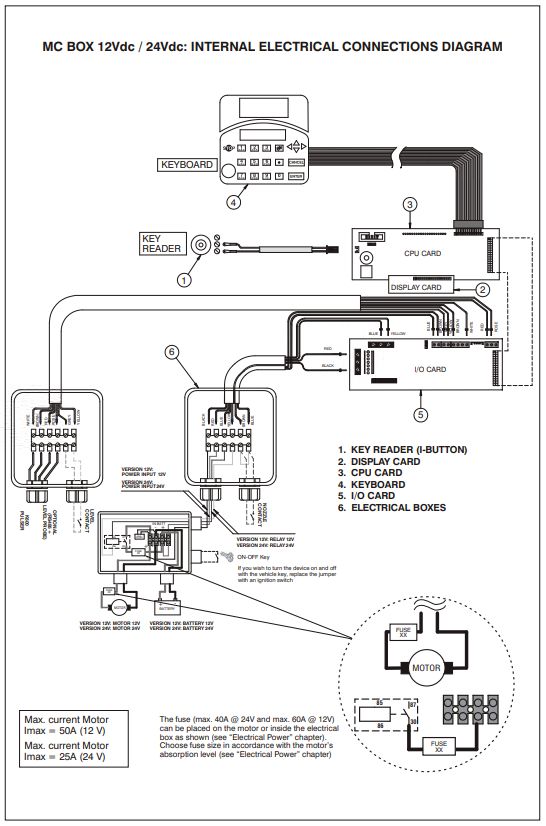
4. MC BOX FUEL MANAGEMENT OPTION Optional
• PC Software with dedicated RS converter or i-button reader to export
MC BOX Electronic Panels are designed for the private distribution of fuel data.
(or other liquids). • I-button keys for users.
• High-accuracy oval gear flow meters.
All of the models in the series are characterised by the same form for
which the MC BOX is known: a solid metal structure, high-accuracy Performance
measurements in the dispensed product and PC software that is designed • 80 or 120-user capacity (depending on model), managed via password
for simplicity. or i-button key.
• Total consumption calculation for defined periods for each user.
This electronic panel allows you to control and monitor private use fuel • Local memory that can store data until the last 255 dispenses.
consumption via a fuel dispenser with pump and flow meter. • Vehicle identification and mileage tracking option.
• Dispensing date and time control.
The MC system consists of a multi-user panel, dedicated software and • Dedicated software that allows you to print dispense data for each user.
the option to connect to a PC. • Ability to manage up to 16 control panels with one single software.
• Key reader with USB plug for exporting data.
The MC BOX System has the ability to: • RS converter with USB plug for direct connection to the PC via cable
• Switch the pump on; (up to 1000 m)
• Recognise authorised users;
• Preset the dispense quantity; MC Box Installation
• Manage the pulse meter;
• Manage an external level switch that turns off the pump in the event of General
minimum flow level; The MC BOX can be installed outdoors. Nevertheless, it is advisable to
• Operate an external nozzle switch; locate it under the shelter of a roof to ensure the dispenser’s longevity
• Connect directly to a PC; and provide greater comfort during refueling in the event of bad weather.
• Connect to an external printer The installation of the dispenser must be carried out by skilled personnel
and performed according to the instructions provided in this chapter.
The panel is easy to install and is adequately protected. The wiring
connections can be easily accessed. The group can also be supplied Electrical connections
with a meter, to be installed together with the pump. The power connections must be workmanlike performed by skilled
personnel, in strict compliance with the laws applicable in the country
Specifications of installation and with the instructions on the wiring diagrams in this
Panel with dual display, keyboard and i-button reader. manual.
The electric box can be opened, allowing easy access to the wiring.
Maximum power supply: 6.5 amps.
287. OPERATION OF THE SYSTEM
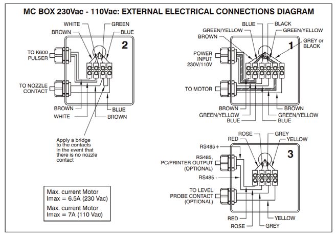
The MC BOX is equipped with 3 junction boxes. These can easily be DC Versions:
accessed by opening the door to where the screw terminals for the
external cable connections are located.
Inputs Outputs Note
DC Power Supply DC motor power Voltage: 12Vdc or
WARNING is the same as the 24Vac, depending
Before accessing the electrical parts, be sure that you have supply voltage on the maximum
disconnected all of the general switches that power off the device. power of the
pluggable motors:
• 12Vdc version
The connections that need to be made vary according to the model (AC or = 600 W
DC): • 24Vdc version
= 600 W
AC Versions:
Power input WITH By removing
IGNITION ON. a jumper and
Given the DC inserting the “in
Inputs Outputs Note
systems’ high power ignition” contact
AC mains supply AC motor Voltage: 230Vac or absorption, the motor in its place, the
power the 110Vac, depending on should be powered electronics can
samevoltage the maximum while the battery is be powered only
as the mains- power of the pluggable being recharged when the vehicle is
motors: switched on
• 230Vac version
Nozzle contact:
= 1400 W
clean contact: Open
• 110Vac version
with nozzle replaced
= 750 W
and Closed when
Nozzle contact: nozzle dispensing
clean contact: Open with
Level contact:
nozzle replaced and Closed
clean contact: Open
when nozzle dispensing
with nozzle in normal
Level contact: conditions and Closed
clean contact: Open with below the minimum
nozzle in normal conditions flow level
and Closed below the
Pulse meter input:
minimum flow level
clean contact or
Pulse meter input: Open Collector output
clean contact or Open signal, with 60 Hz
Collector output signal, with maximum frequency
60 Hz maximum frequency and between 20% and
and between 20% and 80% 80% duty cycle
duty cycle
The RS 485 The RS 485 data
data line line to the PC
to the PC (optional)
(optional)
29You can also read