Ceiling Mount OWNER'S MANUAL - WCM 092315
←
→
Page content transcription
If your browser does not render page correctly, please read the page content below
Ceiling Mount
OWNER’S MANUAL

      The Coolest Thing In Wine Storage
                       WCM 092315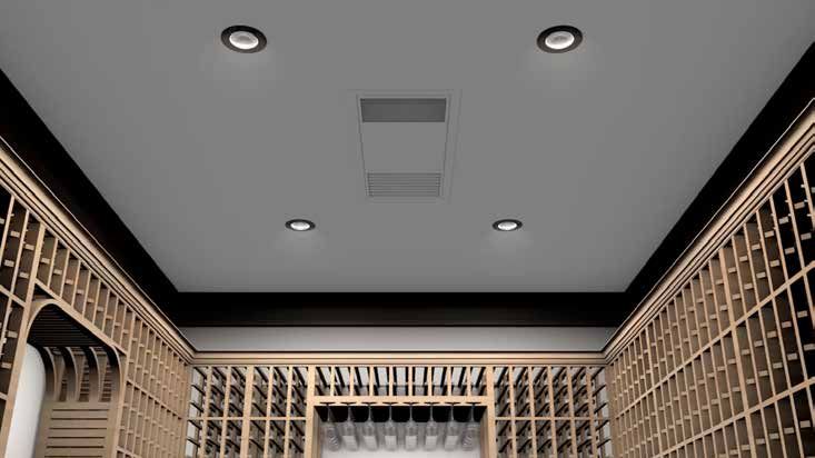
Conforms to ANSI/UL Std 427

Certified to CAN/CSA Std C22.2 No. 120

                 We manufacture, test and certify 100% of our wine cooling units in
                the USA. By sourcing the best components and closely controlling our
                    manufacturing processes, we can assure the highest-quality,
                          lowest defect manufacturing rates in the industry.

                                       Copyright © 2012. WhisperKOOL. All rights reserved.

WhisperKOOL copyrights this manual, the product design, and the design concepts, with all rights reserved. Your rights with
regard to the hardware and manual are subject to the restrictions and limitations imposed by the copyright laws of the USA.
Under copyright laws, this manual may not be copied, reproduced, translated, transmitted, or reduced to any printed or electronic
medium or to any machine-readable form, for any purpose, in whole or in part, without the written consent of WhisperKOOL.

Every effort has been made to ensure that the information in this manual is accurate. WhisperKOOL is not responsible for printing
or clerical errors.

WhisperKOOL reserves the right to make corrections or improvements to the information provided and to the related hardware at
any time, without notice.

Vinothèque and WhisperKOOL are registered trademarks, and ECE is a trademark of WhisperKOOL. All rights reserved.

Mention of third-party products is for informational purposes only and constitutes neither an endorsement nor a
recommendation. WhisperKOOL assumes no liability with regard to the performance or use of these products.

                                                              REV 02

                                                                                                                      WCM 092315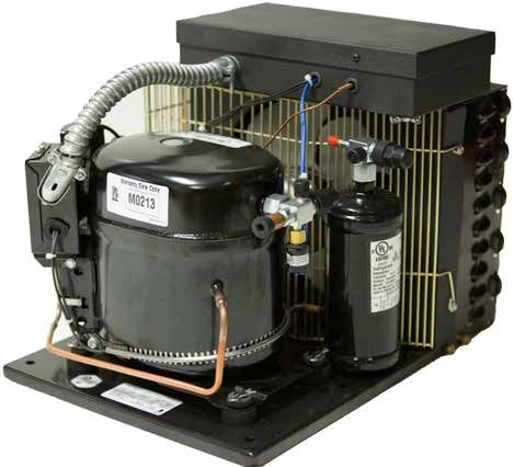
TABLE OF CONTENTS
Quick Reference Guide
   Unit . . . . . . . . . . . . . . . . . . . . . . . . . . . . . . . . . . . . . . . . . . . . . . . . . . . . .  2
   Knockout Location. . . . . . . . . . . . . . . . . . . . . . . . . . . . . . . . . . . . . . .  3
   Controller Layout & Specifications. . . . . . . . . . . . . . . . . . . . . . . .  4

Introduction. . . . . . . . . . . . . . . . . . . . . . . . . . . . . . . . . . . . . . . . . . . . . . . .  6

Warranty Registration. . . . . . . . . . . . . . . . . . . . . . . . . . . . . . . . . . . . . .  6

Receiving & Inspecting the System. . . . . . . . . . . . . . . . . . . . . . . . .  7

Before You Start . . . . . . . . . . . . . . . . . . . . . . . . . . . . . . . . . . . . . . . . . . . .  8

Preparing the Wine Cellar. . . . . . . . . . . . . . . . . . . . . . . . . . . . . . . . . . .  9

Preparing the installation Location. . . . . . . . . . . . . . . . . . . . . . . . .  12

Installing the Evaporator With Attic Access. . . . . . . . . . . . . . . . .  15

220V Connection for Ceiling Mount Evaporator. . . . . . . . . . . .  20

Installing the Evaporator from Inside of Cellar . . . . . . . . . . . . .  21

Drain Line. . . . . . . . . . . . . . . . . . . . . . . . . . . . . . . . . . . . . . . . . . . . . . . . . . .  24

Liquid Thermostat (Bottle Probe). . . . . . . . . . . . . . . . . . . . . . . . . . .  25

Remote Keypad. . . . . . . . . . . . . . . . . . . . . . . . . . . . . . . . . . . . . . . . . . . . .  26

Ceiling Mount Wiring Diagram . . . . . . . . . . . . . . . . . . . . . . . . . . . . .  27

Ceiling Mount 4000 Condensing Unit Wiring Diagram . . . . .  28

Ceiling Mount 8000 Condensing Unit Wiring Diagram . . . . .  29

Preparing the Condensing Unit. . . . . . . . . . . . . . . . . . . . . . . . . . . . .  31

Cold Weather Start Installation. . . . . . . . . . . . . . . . . . . . . . . . . . . . .  31

Condensing Unit Quick Reference Guide. . . . . . . . . . . . . . . . . . .  32

Line Set Piping Diagrams. . . . . . . . . . . . . . . . . . . . . . . . . . . . . . . . . . .  36

Installing the Condensing Unit. . . . . . . . . . . . . . . . . . . . . . . . . . . . .  37

System Operation. . . . . . . . . . . . . . . . . . . . . . . . . . . . . . . . . . . . . . . . . . . 39

Controller Functions. . . . . . . . . . . . . . . . . . . . . . . . . . . . . . . . . . . . . . . .  40

Maintenance Schedule . . . . . . . . . . . . . . . . . . . . . . . . . . . . . . . . . . . . .  43

Troubleshooting Guide. . . . . . . . . . . . . . . . . . . . . . . . . . . . . . . . . . . . .  44

Technical Assistance & Accessories. . . . . . . . . . . . . . . . . . . . . . . . .  46

Installation Terms and Conditions. . . . . . . . . . . . . . . . . . . . . . . . . .  47

                                                                                                               www.whisperkool.com | Page 1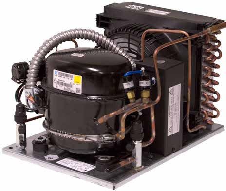
QUICK REFERENCE GUIDE
                                                         Bottom View

                                    Evaporator Unit (Fan Coil Unit)

                       Line Set Knock Out (x6)

Electrical Knockouts

                                                                                    Supply and Return Grille (Paintable)

      Mounting Bracket (Paintable)

                                                            Top View

  Electrical Knockout
        Options

                                                                                                       Top Panel

                                 Line Set Knockout
                                      Options

                                   Note: The unit comes black. The mounting bracket and front grille
                                       are paintable, enabling you to match your desired color.

  Page 2 | 1-800-343-9463                                                                                           WCM 092315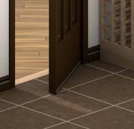
8                       7                    6                             5                                               4

                                  KNOCKOUT LOCATIONS

D

                                                       2x           1.50 Knockout
        5.55”

    14.1” 3”                                                         Top View of Evaporator Unit
               1.55”

        5.55” 1.5”
                                   2x      0.84 THRU
                2.5”
C

                       1.75”            13.25”                              20.75”
                                                       35.75”

                                                                      2x    1.50 Knockout
                                   2x      0.84 THRU                       (Both Sides)

               4.57”                                                                                                 4.29”

B               1.5”                                                 Side View of Evaporator Unit                     2”
        12.65”                                                                                                               12.65”

               6.58”                                                                                                 6.36”

                       1.75”            13.25”                              20.75”
                                                       35.75”

                                                                                                                                                                   UN

                                                                                                                                                                   DIM
                                                                                                                                                                   TO
                                                                                                                                                                   FR
                                                                                                                                                                   AN
A                                                                                                                                                                  TW
                                                                                                                                                                   TH

                                                                                                                                                                   INT
                                                                                      PROPRIETARY AND CONFIDENTIAL                                                 TO
                                                                                                                                                                   MA

                                                                                                                                                                   FIN
                                                                                                                               NEXT ASSY                 USED ON

                                                                           Top View                                                        APPLICATION

                   8                       7                    6                              5                                              4

                               Side View

                                                                                               www.whisperkool.com | Page 3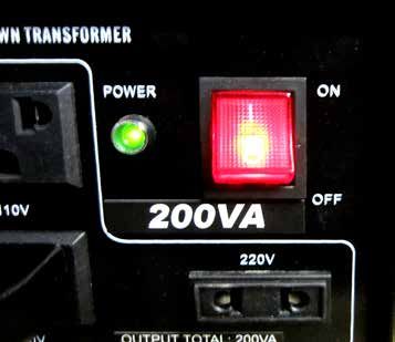
QUICK REFERENCE GUIDE
                                                Controller Layout
                                     Refer to page 44 for complete listing of buttons
                                                                                °F    and
                                                                                        °Fsymbols.
                                                                                                                   High Bottle Temp
                                                                                                                       History
                                           °F                                                                        Scroll Button
                                                                                                                    Cellar Pre-Chill
                                    °F          °F
         Inactive                                                                                                  (Press and hold 3-5 sec)

                                                                                  °F                               Low Bottle Temp
                                                                                                                       History
    View Set Point                                                                                                   Scroll Button
   Change Set Point
   (Press and hold 3-5 sec)
                                                                                                                    Power On/Off

                                    Compressor is On                           Unit is in Pre-Chill Mode

                                    Fans are On                                Alarm is Present

                                    Unit is in Anti-Frost Mode

                                     CEILING MOUNT SPECIFICATIONS
                                             4000 Evaporator                                      4000 Condenser
Model
                                              (Fan Coil Unit)                              (Air Cooled Condensing Unit)
Cellar Size (cu. ft.)                                                          1000
Dimensions                               35.75”L x 14.5”W x 12.65”H                              16”L x 11.5”W x 10”H
BTUh with 90° air entering
the Condenser Coil*
                                                                               3650

CFM                                                  321                                                   190
Refrigerant                                                                   R-134a
Condensing Unit HP                                                            1/3++
Voltage Rating (20 amp                                                    115V or 230V
dedicated circuit required)

Weight (lbs)                                          80                                                   56
AMPS (Starting/Running)                              2/1                                                23.5/6.8
dBA                                                  58.5                                                  65
Drain Line                    1/4” Condensate
                              Evaporator unit (fan coil unit) is installed through the cellar ceiling, condenser is installed up
Installation
                              to 100 line ft. from the evaporator unit.
Thermostat                    Digital Control Display
Temp. Delta                   55°F max. temperature differential between the cellar temperature and condenser air intake temperature.
Warranty                      2-year parts and labor

Page 4 | 1-800-343-9463                                                                                                   WCM 092315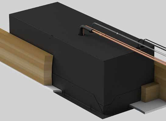
CEILING MOUNT SPECIFICATIONS
                                               8000 Evaporator                                      8000 Condenser
 Model
                                                (Fan Coil Unit)                              (Air Cooled Condensing Unit)
 Cellar Size (cu. ft.)                                                          2000
 Dimensions                              35.75”L x 14.5”W x 12.75”H                              17.5”L x 13”W x 13.5”H
 BTUh with 90° air entering
 the Condenser Coil
                                                                                4450

 CFM                                                  321                                                   350
 Refrigerant                                                                   R-134a
 Condensing Unit HP                                                              1/2
 Voltage Rating (20 amp                                                    115V or 230V
 dedicated circuit required)

 Weight (lbs)                                          80                                                   69
 AMPS (Starting/Running)                              2/1                                                43.6/8.7
 dBA                                                  58.5                                                  65
 Drain Line                    1/4” Condensate
                               Evaporator unit (fan coil unit) is installed through the cellar ceiling, condenser is installed up
 Installation
                               to 100 line ft. from the evaporator unit.
 Thermostat                    Digital Control Display
 Temp. Delta                   55°F max. temperature differential between the cellar temperature and condenser air intake temperature.
 Warranty                      2-year parts and labor

* Sizing the Unit to the Room
The specification chart will provide information on the units room size cooling capacity. There are circumstances in
which a cellar design may require a larger unit due to some existing design restrictions. There are several factors such as
glass, stone, concrete, etc. which will seem adequate but do not offer the insulation capacity required to maintain the
optimum environment. We recommend purchasing a unit with a larger capacity to compensate for the design limita-
tions. Under sized cooling units can lead to pre-mature failure and/or prevent the system from reaching the desired set
temperature. As a result they are not covered under warranty.

                                                                                                        www.whisperkool.com | Page 5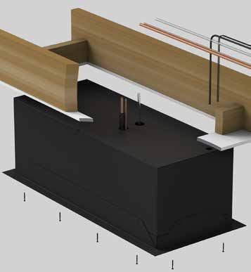
INTRODUCTION
Customer Service
Thank you for purchasing a WhisperKOOL cooling system. We strive to provide the highest quality products and the
best possible customer service. If you have any questions about your system, please call us at 1-800-343-9463 or visit
WhisperKOOL.com.

Using the Manual
This Owner’s Manual is intended to assist in the proper maintenance of the cooling system. In order to ensure the
longevity of your cooling unit, the equipment should be installed as outlined in the this Owner’s Manual. It is also vital
to establish a proper care and maintenance schedule. Please read and review this Owner’s Manual carefully and keep it
for future reference.

What is the WhisperKOOL Cooling System?
The WhisperKOOL cooling system is a specialized refrigeration system designed for one purpose only: to maintain
the optimal temperature and humidity levels conducive to the proper storage and aging of fine wines. This system
produces minimal in-cellar noise and has the most lenient exhaust requirements. An exterior housing is required for
outdoor condensing unit installations.

How Does the Cooling System Work?
Similar to the air conditioning systems used for homes, the evaporator and condensing units are installed in separate
locations and are connected by a refrigerant line set. The evaporator portion is commonly installed in the wine cellar,
with the condensing unit located either outside or in a remote indoor location that is ventilated. An exterior housing is
required for outdoor condensing unit installations.

Temperature Setting
The WhisperKOOL system can be set at any temperature within the acceptable wine-aging range of 50°F to 70°F. It
is designed to cool up to 55°F cooler than the ambient temperature of the space to which the condensing unit is
installed.

                                    WARRANTY REGISTRATION

In order to activate the warranty of your system, the Verification and Operational
   Documentation must be completed by the certified refrigeration technician
           installing your system and submitted via mail, fax or e-mail.

            Mail to:                                    Fax to:                     Scan and e-mail to:
            WhisperKOOL                              209-466-4606               warranty@whisperkool.com
            ATTN: Warranty Registration     OR                          OR
            1738 E. Alpine Avenue
            Stockton, CA 95205-2505
            USA

Page 6 | 1-800-343-9463                                                                                     WCM 092315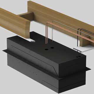
RECEIVING & INSPECTING THE SYSTEM
Receiving and Inspecting the System
   • Lift only at the designated hand hold locations on the shipping container or fully support the unit from
           underneath. A shipment may include one or more boxes containing accessories.
      •    Inspect the packaging for any obvious signs of damage or mishandling before opening the container.
      •    Note any discrepancies or visual damage on the Bill of Lading before signing.
      •    Place the box containing the unit on a tabletop to prepare it for testing prior to installing.
      •    Sit unit upright for 24 hours.
                   Note: WhisperKOOL units are manufactured in the USA and tested prior to shipment.

Review the Packing Slip to Verify Contents
   • Check the model number to ensure it is correct.
   • Check that all factory options ordered are listed.
                       If any items listed on the packing slip do not match your order information,
                                  contact WhisperKOOL Customer Service immediately.

Check the Evaporator Unit (Fan Coil Unit) Box for the Following Contents:

  •       Ceiling Mount Evaporator Unit (Fan Coil Unit)

  Accessory Kit:                                            •   (12) #8 x 3/8” Black Oxide Screws
   • (12) #14 2” Phillips Pan Head Screw                    •   (2) 7/8” Plugs
   • (1) 1/4” Drain Tube Connector                          •   (1) Small Strain Relief
   • (1) 10 ft. 1/4” Drain Line                             •   (2) Cable Ties
   • (1) 50’ Bottle Probe                                   •   (2) Cable Tie Holders
   • (1) Remote Keypad                                      •   (1) ∏” Plug
   • (1) 50’ Keypad Connection Cable                        •   (1) Anti-Siphoning Device
   • (1) Remote Box
   • (1) Split System Warranty Checklist
   • (2) Strain Reliefs
   • (1) Ceiling Mount Owner’s Manual
   • (1) Mounting Bracket

Check the Condenser Box for the following contents:
  •       Ceiling Mount Condensing Unit
  Accessory Kit Two:
   • (1) 1/4” Sight Glass
   • (1) 1/4” Filter Drier

Please leave the unit in its original box until you are ready for installation. This will allow you to move the product
safely without damaging it. When you are ready to remove the product from the box, refer to the installation
instructions.

 TIP: Save your box and all packaging materials. They provide the only safe means of transporting/shipping the unit.

                                                                                              www.whisperkool.com | Page 7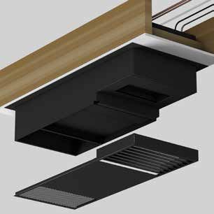
BEFORE YOU START

1. Inspect the system before installation. If damage is found, please contact your distributor or WhisperKOOL
    Customer Service at 1-800-343-9463.
2. The condensing unit requires a dedicated 115 volt 20 amp circuit. Use a surge protector with the unit. Do not use
    a GFI (Ground Fault Interrupter) line.
3. It is REQUIRED to install a drain line to remove condensation from the evaporator unit.
4. The system is intended for use in properly designed and constructed wine cellars. Hire a professional wine
    storage consultant with a valid contractor’s license to build your wine cellar.
5. WhisperKOOL requires that all Split Systems be installed by a certified HVAC-R technician only.
6. Warranty is not active until a Warranty Checklist has been received, reviewed, and approved.

If you encounter a problem with your WhisperKOOL system, please refer to the Troubleshooting Guide on page 48.
If you have any further questions, concerns, or need assistance, please contact WhisperKOOL’s Customer Service at
1-800-343-9463. Please be sure all testing has been completed prior to contacting Customer Service. Please have your
results ready for your representative.

Page 8 | 1-800-343-9463                                                                                WCM 092315
PREPARING THE WINE CELLAR
The performance and life of your system is contingent upon the
steps you take in preparing the wine cellar.
Note: Improperly preparing your enclosure or incorrectly installing your
unit may cause unit failure, leaking of condensation, and other negative side effects.
IT IS HIGHLY RECOMMENDED THAT YOU OBTAIN THE ASSISTANCE
OF A WINE STORAGE PROFESSIONAL.
Wine storage professionals work with licensed contractors, refrigeration technicians, and racking companies to build
well insulated, beautiful, and protective wine cellars. WhisperKOOL has provided useful tips to assist in the installation
process. Our recommendations are meant to act as a guide in the process of building a proper enclosure. Your
intended location may have specific needs that we do not address.
Wall & Ceiling Framing
Build wine cellar walls using standard 2x4 or 2x6 construction methods and ceiling joists following the guidelines of
local and state codes in your area. As a general rule, the thicker the walls and the higher the insulation value in your
cellar, the better it will be at maintaining a consistent temperature.
Insulation
Insulation is REQUIRED with the use of the WhisperKOOL product. Standard fiberglass or rigid foam insulation is
normally used in cellar construction or, in some cases, “blown-in” insulation is used. It is very important that all walls
and ceilings are insulated to keep the cellar temperature as consistent as possible during the summer and winter
months. The R-value, or quality of insulation, is determined by the rate at which heat passes through the insulation.
The higher the R-value, the more resistant the insulation is to conducting heat. Using higher R-values in insulation will
lower your operating costs and unit run time. (R-13 minimum, R-19 recommended, R-30 for ceiling and exterior walls.)
Vapor Barrier
Water vapor creates its own pressure (separate from the air pressure) and will intrude into colder/drier areas. A vapor
barrier is REQUIRED to prevent the intrusion of water vapor so that the cellar can be kept at the correct temperature
and humidity. 6 mm plastic sheeting (recommended) should be applied to the warm side of the cellar walls. The
vapor barrier must also be applied to the outside walls and ceiling. If it is impossible to reach the outside, then the
plastic must be applied from within the cellar. The most common method is to wrap the entire interior, leaving the
plastic loose in the stud cavity so the insulation can be placed between each stud. All of the walls and ceiling must be
wrapped in plastic for a complete vapor barrier.
In areas of high humidity, such as Southern and Gulf States, the vapor barrier will prevent infiltration of warm, moist
air. The moist air can cause mold to form, and standing water in drain pans promote microbial and fungal growth that
cause unpleasant odors and indoor air quality problems. If mold is found, remove it immediately and sanitize that
portion of the unit.
Note: High humidity significantly increases the heat load on the cooling system.
Any break in the vapor barriers (cut, nail hole, over-lapping, etc.) will allow a moisture leak and must be sealed. The
electric conduit is a “duct” for vapor to travel in. The conduit should be caulked and sealed on the warm air end.
www.whisperkool.com | Page 9Unobstructed Airflow
Unobstructed airflow to and from the system is critical for the system’s overall performance and life span. A
minimum three-foot clearance (five-foot is ideal) area is crucial. The air blown by the fans needs to circulate and either
dissipate or absorb heat from the space. The system will operate more efficiently with a greater amount of air to
exchange.
Note: Avoid attempting to camouflage the unit. This will restrict
airflow, and thus the system’s ability to work efficiently.
Door and Door Seal
An exterior grade (1 3/4”) door must be installed as a cellar door. It is very important that weather stripping is attached
to all 4 sides of the doorjamb. A bottom “sweep” or threshold is also required. The door must have a very good seal
to keep the cool cellar air from escaping out of the cellar. One of the most common problems with cooling systems
running continually is due to the door not sealing properly. In cases where glass doors are used and the room size
is close to the recommended system size, the next larger size WhisperKOOL system should be used. This will
compensate for the insulation loss due to the lower insulating rating of glass.
Page 10 | 1-800-343-9463 WCM 092315Ventilation
The necessity of dissipating heat away from the condensing unit is critical to the performance and cannot be
overstated. As the system operates and cools, a greater amount of heat is generated on the condensing side of the
system. Adequate ventilation is required in order to dissipate heat away from the condensing unit. If ventilation is
inadequate, the exhaust will heat the area or room and adversely affect the system’s ability to cool. In some cases, it
may be advisable to install a vent fan to dissipate heat within the exhaust area on the condensing side of the system.
However, you must have a fresh air inlet as well.
Note: If you are unsure about having adequate ventilation in your install location, please
contact us to assess your specific installation at support@whisperkool.com or 1-800-343-9463.
CEILING
EVAPORATOR
UNIT
Note: The unit comes black. The mounting bracket and front grille
are paintable, enabling you to match your desired color.
Ambient Temperature Factor
The cooling system has the ability to cool a wine cellar efficiently to 55°F as long as the ambient temperature of the
area that it is exhausting to does not exceed 110°F. Therefore, you want to exhaust the condensing unit in a space which
will not exceed 110°F and will allow for proper dissipation of the heat exhausted by the condensing unit. Without proper
heat dissipation the system will not have the capacity to keep the wine at a desirable 55°F.
WARNING! allowing your system to operate in high ambient temperatures for
extended periods of time will greatly decrease the life of your system and void
your warranty. The cooler the temperature of the air entering the condenser coil,
the more cooling capacity the system has. The less heat gain through the common
wall, the lower the consumption of electricity.
www.whisperkool.com | Page 11PREPARING THE INSTALLATION LOCATION
Minimum Tools Needed:
T-Square
Hammer Phillips Head #2 Saw
Screwdriver
Locate the desired installation location. Using a stud finder, locate the ceiling
joists on either side of the center point. Cut and frame an opening in the
ceiling measuring 14.5” x 36”. Make sure the framing is sufficient to support
the weight of the cooling unit. It is highly recommended to use only the
mounting locations provided. These locations ensure that the installer
will not drill into any copper or electrical within the system.
Flush Mount
Mounting Option
1
12.65”
Partially Recessed
Mounting Option
6.9”
2
5.75”
Choose a Mounting
Option suitable
for the installation
location.
5.75”
3
6.9”
Fully Exposed
Mounting Option
4
12.65”
Page 12 | 1-800-343-9463 WCM 092315NOTES
www.whisperkool.com | Page 13INSTALLING THE EVAPORATOR UNIT (TYPICAL INSTALLATION)
ITEMS TO ROUTE BEFORE INSTALLING THE EVAPORATOR
1. Route the line set from the condensing unit to the desired evaporator installation location.
2. Route the keypad cable from the desired keypad location to the evaporator installation location (see page 26 for
more keypad information).
3. Route the bottle probe cable from the desired thermostat bottle location to the evaporator installation location
(see page 25 for more bottle probe information).
4. Route the drain line from a proper discharge location to the evaporator installation location (see page 24 for more
drain line Information).
5. Route the power cable wiring to the evaporator installation location.
ITEMS TO ROUTE
LINE SET
KEYPAD CABLE
BOTTLE PROBE
DRAIN LINE
POWER CABLE
Page 14 | 1-800-343-9463 WCM 092315INSTALLING THE EVAPORATOR UNIT WITH ATTIC ACCESS
PREPARING THE EVAPORATOR FOR INSTALLATION
1. Place the evaporator on a working table with the Top 6. Using 1/4” and 1/2” copper tubing, route the liquid and
Access Panel facing up as shown in Figure 1. suction lines through the knockouts in the wrapper.
Note: 1/2” copper tubing will slip over the 3/8” suction
line on the evaporator for an easy connection.
7. Place a wet rag around the suction and liquid lines
approximately 4” from the braze joints. This will
TOP VIEW prevent excess heat from damaging components.
8. To prevent oxidation, purge nitrogen through the
system.
Figure 1 9. Braze the copper tubing to the connections on the
2. Unscrew the 16 screws and remove the Top Access evaporator unit
Panel. 10. Insulate the suction line using Armaflex or similar
3. Remove the Knockout(s) you will be using to route the insulation.
Line Set into the unit. 11. Route the drain line out of the evaporator unit with the
4. Remove the Knockout(s) that you will be using to route line set.
the items on the previous page into the unit (power
cable wiring, keypad cable, and bottle probe cable).
LINE SET DRAIN LINE
5. Remove the protective caps from the liquid and
suction line connection tubes. (as shown below)
Note: Line Set and drain line should extend to the exterior of
the unit through the Knockout(s). Dimensioned Locations of
the knockouts are provided on page 3.
www.whisperkool.com | Page 15INSTALLING THE EVAPORATOR UNIT WITH ATTIC ACCESS
PREPARING THE EVAPORATOR FOR INSTALLATION CONTINUED
12. Reinstall the protective caps on the end of the line set to prevent debris from entering the system.
13. Reinstall the Top Access Panel and fasten the 16 screws into place.
14. Secure the mounting bracket to the unit as outlined on the next page.
Note: It is highly recommended to use only the mounting locations provided. These locations ensure that the
installer will not drill into any copper or electrical within the system.
LINE SET DRAIN LINE
POWER CABLE
WIRING
KNOCKOUT
BOTTLE PROBE &
KEYPAD WIRING
KNOCKOUT
MOUNTING BRACKET
Page 16 | 1-800-343-9463 WCM 092315INSTALLING THE EVAPORATOR UNIT
Single Piece Mounting Bracket
The mounting bracket has been designed to secure the unit to the ceiling. Install the
mounting bracket to the evaporator unit following the guide below.
Mounting Bracket Installation
Using the guide below, select the desired mounting orientation and slide the mounting bracket onto the unit. Align
the mounting holes on the mounting bracket with the pre-drilled holes on the unit. Fasten the mounting bracket to
the unit using the supplied 1/2” self-tapping screws. Slide the unit through the framed opened in the ceiling. Secure
the unit to the opening using the 12 supplied 1 3/4” hex head screws.
Note: It is highly recommended to use only the mounting locations provided. These locations ensure that the
installer will not drill into any copper or electrical within the system.
1. Secure the mounting bracket to the unit.
2. Secure the unit’s mounting bracket to the opening using the 12 supplied 1 3/4” hex head screws.
Routed Items:
1. Keypad & Bottle Probe Wiring
2. Power Cable Wiring
3. Drain Line
4. Line Set
www.whisperkool.com | Page 17INSTALLING THE EVAPORATOR UNIT WITH ATTIC ACCESS
CONNECTING THE EVAPORATOR UNIT
1. Insert the following items into the unit through the 6. Connect the power cable to the evaporator.
removed knockouts: power cable wiring, keypad cable,
bottle probe cable and humidistat cable (optional). 7. Connect the keypad cable to the evaporator (see page
26 for more keypad information).
Note: The diagram on page 16 labels the knockouts to route
theses items into.
2. Remove the eight screws securing the supply and
return air grille.
8. Connect the bottle probe cable to the evaporator (see
3. Grasp the grille and pull straight down. This will release page 25 for more bottle probe information).
the grille from the ball studs.
9. Slide the electrical panel back into the evaporator unit
and secure with the thumbscrew.
10. Re-install the control access panel.
4. Remove the two screws securing the Control Access
Panel in place and remove the panel.
5. Remove the thumbscrew holding the electrical panel
and slide the panel.
Page 18 | 1-800-343-9463 WCM 092315INSTALLING THE EVAPORATOR UNIT WITH ATTIC ACCESS
CONNECTING THE EVAPORATOR UNIT IN THE ATTIC
11. Connect the drain line following the directions on page 24.
12. Remove the caps on the end of the line set.
13. Purge nitrogen through the system.
14. Braze the line set to the suction and liquid line ports on the evaporator unit.
15. Seal all gaps around the unit using expanding foam.
16. Using fiberglass insulation, wrap any part of the wrapper that is not inside the cellar. This will prevent
condensation from forming on the wrapper.
17. If desired, paint the mounting bracket and Front Access Panel to match the color of the ceiling.
BRAZE LINE SET USING
COUPLING
CONNECT THE
DRAIN LINE
TUBING
THE NEXT SECTION IS AN INSTALLATION PROCESS FOR
SITUATIONS WHERE ATTIC ACCESS IS NOT AN OPTION.
www.whisperkool.com | Page 19220V CONNECTION FOR CEILING MOUNT EVAPORATOR UNIT
NOTE: These Instructions are only for units equipped with the 220V option selected at time of purchase.
1. Connect the supplied power cord with the exposed wire ends
to the evaporator unit following the wiring instructions in this
Owner’s Manual.
2. Plug the power cord into one of the outlets labeled 110V on the
transformer.
3. On the back of the transformer make sure that the switch is set to 220V.
4. Plug the transformer in to a 220-230V power source.
5. To apply power to the unit move the switch on the front of the unit to the “on” position.
Page 20 | 1-800-343-9463 WCM 092315INSTALLING THE UNIT FROM INSIDE THE CELLAR
NOTE: The Ceiling Mount Unit can still be used even with limited or no above ceiling access. For installations with
limited or no above ceiling access, do not remove the top of the evaporator unit. Follow the instructions below for
installation.
1. Remove the knockouts from the top of the unit for 4. Route the line set, drain line, water line, power
the line set and electrical. wires, keypad cable, and bottle probe cable into
the evaporator housing through the knockouts
removed in the first step.
2. Route all electrical and tubing to the installation
location as outlined on page 14.
LINE SET POWER CABLE BOTTLE PROBE &
WIRING KEYPAD WIRING
KNOCKOUT KNOCKOUT
DRAIN LINE
5. Mount the evaporator unit to the ceiling using the
supplied 1 ¾” hex head screws.
3. Install the mounting bracket as shown on page 17.
Note: Depending on installation location, the Flush Mount
mounting option might not be suitable.
www.whisperkool.com | Page 21INSTALLING THE UNIT FROM INSIDE THE CELLAR
6. Remove the eight screws securing the supply/return air 10. Remove the 3 nuts holding the pump bracket in place.
grille. Pull the pump bracket down and of the way.
7. Grasp the grille and pull straight down. This will release
the grille from the ball studs.
11. Remove the protective caps on the end of the line set
connections.
8. Remove the two screws holding the drip tray in place.
9. Remove the drip tray.
PROTECTIVE
CAPS
LINE SET
DRAIN LINE
Page 22 | 1-800-343-9463 WCM 092315INSTALLING THE UNIT FROM INSIDE THE CELLAR
12. Connect the line set to the liquid and suction lines on 17. Connect the drain line to the pump discharge line
the evaporator. Note: ½” copper tubing will slip over using the supplied ¼” barbed coupling. Follow the
the 3/8” suction line on the evaporator for an easy directions on page 24 for proper drain line routing.
connection.
13. Place a wet rag around the suction and liquid lines
approximately 4” from the braze joints. This will
prevent excess heat from damaging components.
14. Purge nitrogen though the system to prevent oxig
15. Braze the copper tubing to the connections on the
evaporator unit.
16. Insulate the suction line using Armaflex or similar
insulation.
18. Reinstall the pump bracket and drip tray.
19. Follow steps 4-11 on page 18 to complete the wiring
on the unit.
20. If desired, paint the exterior of the evaporator
housing to match the color of the ceiling.
Note: The unit comes black. The mounting bracket and front
grille are paintable, enabling you to match your desired color.
www.whisperkool.com | Page 23DRAIN LINE
Condensation Drain Line
The condensation drain line tube is used to remove excess condensation from the unit to a proper discharge location. It
is important that the drain line tube is properly connected.
Failure to use the condensation drain line tube will void the warranty on the unit.
Drain Line
The Ceiling Mount evaporator features a drain line pump system that removes excessive condensate build up in the
drain pan. During operation, the drain pan collects water that drips from the coil. The drain line pump system will
prevent overflow and leaking by allowing for discharge of the additional condensate.
The longevity of the drain line pump may be compromised if the system operates dry. To prevent the pump from
starting dry an anti-siphon device must be installed in the drain line tubing as shown in Figure 9. This device should
be installed in the drain line post pump on the exterior of the evaporator unit. WhisperKOOL recommends to install
the anti-syphon device relatively close to the evaporator because water will remain between the pump and the
device.
NOTE: The anti-siphon device only needs to be used when the drain line is routed below the level of the evaporator
unit. In this case the anti-siphon device should be installed in the drain line at the level of the evaporator unit.
Connecting the Drain Line
Route the drain line to an appropriate discharge location using the
supplied barb coupling and 1/4” tubing.
Do not route the drain line more than 30 vertical ft.
Anti-Siphon
Device
FIGURE 9
Proper Drain
Location
WRONG: Drain line is under water.
To prevent mold from growing, allow the Note: Water will remain between the pump and the
drain line to hang above the water line. anti-syphon device at all times.
Page 24 | 1-800-343-9463 WCM 092315LIQUID MEASURING THERMOSTAT SYSTEM
The CellarCool Series cooling units come equipped with a liquid temperature measuring thermostat. This incorporates
the following advantages:
Self-Calibrating Bottle Probe
The bottle probe contains a sensor chip, which communicates back and forth with the thermostat. This results in a
consistent temperature setting and accuracy.
1. Wine should be kept at a very precise, controlled temperature and humidity.
2. By measuring the liquid temperature rather than air, the unit will operate 75–80% of the time.
Setting Up The Bottle Probe: Figure 1
1. Locate an empty wine bottle.
2. Fill 3/4 full with room temperature tap water.
3. Place bottle probe securely into bottle as seen in Figure 1.
4. Place bottle with probe level and to the side of the unit in your wine cellar.
5. To assure a consistent temperature, place bottle probe approximately 3 feet
away from the air output and not in the flow of the air.
It is recommended that the bottle be placed in a central location of your
wine cellar. Avoid pulling too much on the probe cord. It may become
disconnected resulting in limited functionality of the unit.
Note: The thermostat can be set between 50–67°F.
Remember: The CellarCool unit operates based on the temperature of the water.
Do not be misled by thermostats reading air temperature. The air temperature
in the cellar will be cooler than the liquid temperature of the wine while it is
reaching optimum balanced temperature.
www.whisperkool.com | Page 25REMOTE KEYPAD: INSTALLATION AND CONFIGURATION
Note: A 50ft communication cable is included and the keypad can be installed up to 300 feet away from the
evaporator unit. Longer lengths can be ordered by calling 1-800-343-9463 ext. 751.
Route the communication cable from the evaporator unit to the desired keypad location. Remove the wall mount
bracket from the display housing. Using appropriate anchors or fasteners, secure the wall mount bracket to the wall.
If routing the communication cable through a wall, connect the wires to the back of the control panel following
the image below. Connect the red wire to the upper (+) terminal. Connect the black wire to the lower (-) terminal. If
the communication cable is not routed through the wall; remove the plug in the side of the display housing. Route
the cable through the hole and connect to the back of the display as shown below. Reattach the keypad box to the
bracket.
Red Wire
Black Wire
Connection wire in Side Mount configuration Connection wire in Rear Mount configuration
Page 26 | 1-800-343-9463 WCM 092315CEILING MOUNT WIRING DIAGRAM
- +
10 9 8 7 6 5 4 3 2 1
-
+
13 14 15 16 17 18 19 20 21 22
Line
Neutral
White
Black
Black
Black
Purple
Gray
Orange
1 4 (1)
Condensate
Pump
1 4
(4)
Green
Black
Red
Use Copper
Conductor Only
Black Blue
Solenoid
Ref.
Green
Green
Green
Black
White
Black
White Blower
Fan
White
Brown
www.whisperkool.com | Page 27CEILING MOUNT 4000 CONDENSING UNIT WIRING DIAGRAM
Platinum Split 4000 & 8000 Condenser Terminal Board
Page 28 | 1-800-343-9463 WCM 092315CEILING MOUNT 8000 CONDENSING UNIT WIRING DIAGRAM
LEGEND:
TERMINAL BOARD
BD # SERVES COLOR
1 GROUND GREEN
UK GREEN/YELLOW
STRIPE
2 L1-115V-HOT BLACK WHITE (NEUTRAL)
BLACK
RED UK-CAN
3 115V-NEUTRAL WHITE
BLUE UK
4 CC HEATER BLACK
1 2
5 COMP GND GREEN M
UP
6 H-COMP BLACK S L
7 N-COMP WHITE
8 H-COND FAN BLACK START 3 BLUE FAN
RED
9 LINE H-LP-HP BLACK COMPRESSOR
CAPACITOR
1
(CONDENSER)
10 LOAD H-LP-HP BLUE CRANKCASE
HEATER
C
R
S YELLOW
RELAY
TD=TIME DELAY, DELAY ON BREAK
COMPRESSOR OVERLOAD
TERMINAL
GREEN
BLACK-H
BLACK-F
WHITE-NEUTRAL
BLACK-C
ENCLOSURE
W
TD COMP 0 1
RELAY
3 1 DOB
BLACK-NC 7
BLACK-C 8
BLACK-NO 6
BLACK
1 2 3 4 5 6 7 8 9 10 11
G H N 12 13 14 15 16 17 18 19
BLACK-C
WHITE-NEUTRAL LP HP
BLACK-F
BLUE
BLACK-H
GREEN BLACK
LOW
115V 60 HZ GREEN AMBIENT
BLACK CONTROL
POWER WHITE
SOURCE line m1
www.whisperkool.com | Page 29INSTALLING THE CONDENSING UNIT
POWER
H N
115v 60 HZ
CC HEATER
4
START
CAPACITOR
COMP CONTACTOR
CURRENT
RELAY
6 OL
3
COMPRESSOR
7
9 HP 10 LP TD
CC
6 8 COND.
CC COMP CONTACTOR
HP HI PRESS SWITCH LOW AMBIENT FAN
LP LO PRESS SWITCH CONTROL
TD TIME DELAY
Page 30 | 1-800-343-9463 WCM 092315PREPARING THE CONDENSING UNIT
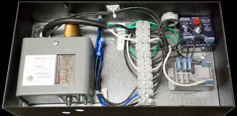
Electrical Needs
The condensing unit requires a dedicated 115 volt 20 amp circuit. The unit draws a large inrush current for about
one second the instant the compressor starts. With a dedicated circuit and circuit breaker, the condensing unit will
have sufficient power for effective operation. (The compressor is controlled by a low-pressure switch mounted on
the condensing unit. This feature eliminates the need for wiring between the evaporator unit (fan coil unit) and the
condensing unit.)
• Ensure the voltage supplied matches the rating specified on the unit spec label.
• Provide a non GFI dedicated circuit and an appropriate outlet for the evaporator unit.
• Provide a dedicated circuit and circuit breaker for the condensing unit.
• Provide a weatherproof disconnect for condensing unit located outside.
As with all sensitive electrical equipment, damage may be caused in the event of power surges and spikes.
WhisperKOOL recommends plugging the unit into a surge protector or power conditioner in order to protect your
system. As outlined in our terms and conditions, power surges and spikes are not covered under warranty.
WE RECOMMEND THAT YOU DO NOT USE A GROUND FAULT INTERRUPTER (GFI) WITH THIS PRODUCT.
In case the system should lose power, check the home/main circuit breaker. If the system does not respond properly,
refer to the Troubleshooting section on page 48.
Cold Weather Start Kit
For systems equipped with the Cold Weather Start Kit; Run a two wire 18-20 awg thermostat wire from the evaporator unit to
the condensing unit. Connect one end of the thermostat wire to the 24v hot and 24v neutral wires located in the evaporator
unit. Connect the other end of the thermostat wire to the 24v hot and 24v neutral wires located in the electrical box on the
condensing unit.
www.whisperkool.com | Page 31CONDENSING UNIT QUICK REFERENCE GUIDE
Ceiling Mount 4000 Condensing Unit
Electrical Box
Liquid Line Fan Cycling Switch
Service Valve Cut Out: 75 psi
Cut In: 120 psi
Low Pressure Switch
Cut Out: 5 psi
Cut In: 20 psi
Suction Line
Service Valve
Ceiling Mount 8000 Condensing Unit
Low Ambient Control
Suction Line Secure Valve
(Inside Electrical Compartment)
Low-Pressure Switch
Page 32 | 1-800-343-9463 WCM 092315PREPARING THE CONDENSING UNIT (continued)
Installing the Condensing Unit
The condensing unit can be installed inside a well-ventilated area of the home, but is typically installed outside.
Exterior applications will require the use of a protective housing, and the amount of sun exposure should be
considered when selecting the placement of the condensing unit .The condensing unit requires a dedicated 20 amp
circuit (non-GFI). Make sure there is a minimum three-foot horizontal clearance in the front and rear of the unit. The
unit may either be hard wired or plug-in, depending on local electrical codes.
Inside Condensing Unit Installations: Inside installations require special consideration, as there must be
adequate ventilation to remove the heat created during normal operations. An exhaust port with fan may
need to be installed to ensure that heat is effectively removed from the utility room. A return grille or provision
for 500 - 600 cfm of cool air to enter the room to replace the exhausted air will accomplish this. Unobstructed
airflow to and from the unit is a critical factor in the unit’s overall performance. Make sure there is a minimum
three-foot horizontal clearance in the front and rear of the condensing unit and at least one foot on each side.
This will assure that the unit can move the air around the room in an efficient manner.
Outdoor Condensing Unit Installations: You must utilize the exterior condensing unit housing for outdoor
installations. Place the condensing unit on a solid foundation in a location with adequate ventilation. There
should be three feet of clearance in the front and rear of the unit and one foot on each side. The unit should
be elevated 18 inches in order to avoid any possible flooding or damage by animals, and should be clear of
leaves, dirt, and other debris.
www.whisperkool.com | Page 33INSTALLING THE CONDENSING UNIT
Wiring Procedures Ceiling Mount 4000
1. Locate or install an electrical outlet near the condensing unit.
2. Plug the condensing unit’s power cord into the electrical outlet.
3. Leave the circuit breaker off until the unit is ready to charge.
Note: Do not apply power to a system without refrigerant.
Ceiling Mount 4000 Wiring
Time Delay Relay
Compressor Contactor
Page 34 | 1-800-343-9463 WCM 092315INSTALLING THE CONDENSING UNIT
Wiring Procedures Ceiling Mount 8000
1. Route 14 AWG copper wiring to the condensing unit.
2. Remove screw securing the cover to the electrical box. Remove the top cover of the electrical box.
3. Route the wiring through the strain relief in the side of the electrical box and to the terminal block.
4. Tighten the strain relief to secure the wires.
5. Wire the unit as shown in the image below.
6. Verify that the Johnson Control is set for 170 PSIG cut-in and 70 PSIG differential. This may need to be adjusted
based on your ambient temperatures.
7. Verify that the time delay relay is set for 5 minutes.
8. Leave the circuit breaker off until the unit is ready to charge. Do not apply power to a system without refrigerant.
Ceiling Mount 8000 Wiring
Ground
Line
Time Delay Relay
Neutral
Johnson Head Compressor
Pressure Control Constitution
www.whisperkool.com | Page 35LINE SET PIPING DIAGRAMS
These are two options for running the line
set from the coil to the condensing unit. Option 1
Option 1 is specifically for when the system
is installed with the condensing unit below
or leveled to the coil. Option 2 is for when
the system is installed with the
condensing unit at a higher
elevation than the coil.
Option 2
LEGEND
LLS Liquid Line Solenoid
TXV Thermal Expansion Valve
COMP Compressor
REC Receiver
EVAP. Evaporator
O.D. Outer Diameter
It is required to size the suction line tubing according to this chart.
Line Set LengthINSTALLING THE CONDENSING UNIT
Refrigerant Piping Overview
• Using the charts and illustrations found on previous pages, route the line set between the evaporator unit and
condensing unit. Be sure to reference the chart for correct line set sizing. All horizontal suction piping should be
pitched toward the condensing unit ½” for every 10’ of pipe. When installing and routing the line set, cap both
ends of each tube to prevent debris from entering the tubing.
• Prior to connecting the piping to the evaporator and condensing units, loosely connect a refrigerant manifold to
the suction and liquid line service valves.
• Purge the hoses with dry nitrogen and tighten the hose connections.
• Remove the service valve caps and turn the valve stem clockwise ½ turn to unseat the valve and open the
service port. Keep the piping ports sealed until ready to braze.
• Purge dry nitrogen through the fittings at a slow rate to prevent formation of highly abrasive copper oxide.
• Perform all brazes.
• Pressure test the system and check for leaks.
• Insulate the suction line using ½” wall cellular insulation or equivalent. Seal all seams with Armaflex 520 Foam
Insulation Adhesive or equivalent. Wrap each seam using line set tape.
Liquid Line Piping Procedure
• ¼” OD copper tubing is required for the liquid line on all systems.
• Braze a short piece of ¼” copper tubing to the liquid line service valve.
• Connect the supplied refrigerant drier to the tubing.
• Downstream from the drier, connect the moisture indicating sight glass in an easily visible location.
• Run the tubing to the evaporator unit (fan coil unit) and attach to the liquid line connection on the evaporator
unit (fan coil unit).
Suction Piping Procedure
• Install an access valve at the outlet of the evaporator unit (fan coil unit).
• Connect an appropriately sized suction line to the suction line service valve on the condensing unit.
• Run the pre-insulated suction line to the evaporator unit (fan coil unit) and attach to the suction line connection
on the evaporator unit (fan coil unit).
Brazing Procedure
• Connect the bottle probe to the evaporator unit (fan coil unit).
• Fill a wine bottle ¾ full of room temperature water. Insert the bottle probe into the neck of the bottle as far as
possible. It is important that the bottle probe stopper be compressed by the neck of the bottle to ensure water will
not leak.
• Energize the evaporator unit (fan coil unit) and set the controller to call for cooling.
• Verify that the set point on the control is set low enough to allow the unit to run for the entire length of the
brazing, evacuation, and charging procedure.
• Remove the valve depressors from the gauge hoses on a four-valve manifold.
• Connect the manifold to the low-pressure service valve port on the condensing unit and a nitrogen tank.
• Open the suction line service valve and purge nitrogen through the system.
• Braze all connections and cool off quickly.
• Cap the access valve on the suction line.
• Connect the high-pressure hose from the manifold to the liquid line service valve port.
• Pressure test the system at 150 psi for 20 minutes.
• Check all braze joints with leak detector or soap bubbles.
• Release the nitrogen once it is confirmed that there are no leaks.
www.whisperkool.com | Page 37INSTALLING THE CONDENSING UNIT
Evacuation
• Remove the nitrogen tank from the manifold and attach the manifold to the refrigerant tank.
• Install a micron gauge onto the access valve near the evaporator unit (fan coil unit).
• Mid seat both service valves.
• Install service caps on the valves.
• Energize the liquid line solenoid valve.
• After confirming there is fresh oil in the vacuum pump, connect the 3/8” hose from the manifold to the pump.
• Start the pump and run until the micron gauge at the evaporator unit (fan coil unit) reads 200 microns or less.
• Disconnect the vacuum pump from the system.
• Break the vacuum by pressurizing the system to approximately 5 PSI with R-134a.
• Remove the micron gauge from the access valve.
Charging
• Install a low-pressure gauge on the access valve near the evaporator unit (fan coil unit).
• With the power off to the condensing unit, admit liquid refrigerant through the liquid line service valve until the
refrigerant stops flowing.
• Turn on the circuit breaker for the condensing unit. The compressor should turn on if the pressure in the suction
line is above 20 psi.
• Add refrigerant as a vapor through the low side of the system.
• Observe the sight glass. If bubbles are present, add more refrigerant in vapor form to the low side.
• Once the sight glass is clear, check the superheat at the outlet of the evaporator unit (fan coil unit). Adjust the TXV
until the superheat is between 8-12 degrees.
• If TXV adjustment is necessary, remove the drip tray on the evaporator unit to access the TXV from the cellar.
The drip tray is secured to the wrapper with two screws. Once the screws are removed the drip tray will slide
down and out of the evaporator unit.
• Under normal operation, with the wine cellar at 55° and the ambient temperature at 85°, the low side pressure
should be between 28-32 PSI and the high side should be between 170-180 PSI.
Finalizing the Installation
• Confirm that the entire suction line from the TXV to the suction line service valve is insulated using ½” wall cellular
insulation or equivalent. Seal all seams with Armaflex 520 Foam Insulation Adhesive or equivalent.
• Reinstall the drip tray and Front Access Panel.
• Confirm that the control is displaying the correct temperature and that no alarms are present. Refer to page 45 for
corrective action if alarms are present.
FINALIZING THE INSTALLATION
1. Push the Grille Back into place. This will attach the
grille to the ball studs.
2. Screw in the eight screws to secure the Front Access
Panel.
Page 38 | 1-800-343-9463 WCM 092315SYSTEM OPERATION
Initial Start-Up Low Ambient Conditions
When power is applied to the unit, the control will briefly If the condensing unit is installed outdoors (which allows the
display all symbols, and the Snowflake symbol will be displayed condenser to be exposed to low ambient temperatures), the
(if unit is calling for cooling). There may be a brief (up to 60 condenser fan may cycle on and off. The purpose of the fan
sec.) delay prior to the evaporator fan turning on. When the cycling is to maintain the system high side pressure, which
evaporator fan is activated the Fan symbol will display. will ensure an adequate refrigeration process. The fan cycling
process is accomplished by way of a Johnson Control or fan
APST (Advance Product Safety Technology) is a temperature cycling switch attached to the condensing unit.
control feature for the evaporator fan that comes standard with
all WhisperKOOL units. APST ensures that in the possible event Bottle Probe Failure Protection
of a cooling deficiency, the heat from the indoor fan will not In the event that a bottle probe should fail, the APST (Advance
raise the temperature of the wine cellar, which could otherwise Product Safety Technology) will automatically transition the
have an adverse effect on the wine-aging process. refrigeration compressor cycles to a pre-determined time
series (based on detailed laboratory testing), which will ensure
Set Point that the product is kept within the safe range.
The set point is set from the factory (WhisperKool) at 55F°. It
can be adjusted by the customer between 45–67F° in one Display
degree increments. The bottle probe temperature is displayed by default. “Def”
is displayed during Anti-Frost. The air sensing probe and
Cooling Operation evaporator probe temperatures can be accessed by pushing
The FON function is an adjustable feature which allows the the SET button and scrolling through “PB1” (bottle probe), and
customer the convenience of reintroducing some of the “PB2” (evaporator probe).
humidity removed by the fan coil during the cooling process.
The FON Function controls the evaporator fan operation Safety Features
once the set point has been reached. When the bottle probe Once the compressor relay is de-energized the controller must
has reached the set point (all units are shipped with the set wait five minutes before re-energizing the relay. This prevents
point of 55°F and a differential of 1°), the compressor and the the compressor from repeatedly turning off and on. If the unit
condenser fan will turn off, but the indoor fan will continue is calling for cooling during this time, the compressor symbol
to run for about 5 minutes to re-introduce any moisture from will blink, indicating that cooling is needed but the control is
the evaporator coil. All units come with this feature turned waiting for the Anti-Short cycle delay.
off. If low humidity is a problem an increase in this setting
will raise the humidity level. The FON function is one of the In the event of a faulty bottle probe, the compressor will cycle
many Customer Preference Selection features that allow the off for 10 minutes and on for 40 minutes. “E1” will be displayed
customer the ability to fine-tune the controls. on the screen.
Anti-Short Cycle Alarms
The Anti-Short Cycle ensures that the unit will remain off for a See “Alarm Codes” in Controller Function chart.
period of five minutes after the unit has reached the set point
to allow the pressure in the refrigeration system to equalize Remote Control Panel (standard)
prior to starting the compressor. The remote keypad is designed to give the user the ability to
monitor and change cellar conditions when the evaporating
Anti-Frost Cycle (defrost) unit is placed in a remote location outside of the cellar.
The system will go through an Anti-Frost cycle every 4 hours.
This will shut down the compressor and allow the evaporator
and condenser fans to run to evaporate any frost accumulation
on the coil. The compressor will remain off until the evaporator
coil reaches 40F°, or for a maximum of ten minutes. The unit
will then return to normal operation.
www.whisperkool.com | Page 39CONTROLLER FUNCTIONS
High Temp / Pre-Chill
Inactive
Low Temp
Display ON / OFF
Set Point
TEMPERATURE
Button Normal Functions
ON/OFF • The ON/OFF button allows the customer the convenience of turning the refrigeration
system ON or OFF from the control panel. This feature does not disconnect power from
the unit. In order for the power to be shut off from the unit, the power cord must be
unplugged from the wall receptacle.
• Press the ON/OFF button once for button application.
Up and Down • Use these buttons to scroll up or down the CPSM (Customer Preference Selection Mode)
Arrows menu.
• Displays the highest and lowest temperature sensed by the bottle probe. This feature
allows the customer instant access to the recorded data applicable to the bottle probe
Temperatures. It can be easily reset to reflect current temperatures.
1. Press the “UP” arrow, or the “DOWN” arrow once, and the highest or lowest temperature
(Hi/Lo) sensed by the bottle probe will be displayed.
2. To reset the Hi/Lo, press and hold the “Set” button when the Hi/Lo value is displayed on
the Digital Display, continue to hold the “Set” button until “rst” appears on the digital
display and then blinks. This will erase the past-recorded “Temperature Data History” and
start recording from the current time and temperature forward. Temperatures displayed
would reflect bottle probe temperatures from that point in time and beyond.
3. The Hi/Lo feature should be reset at initial “Start-Up” and after the cellar has obtained
normal operating temperatures, which is generally 55°F.
Cellar PreChill (CPC) The CPC feature is activated by pressing the “UP” arrow for 3-5 seconds, and the CPC logo
will be displayed on the digital display. The CPC feature can be terminated by pressing the
“UP” arrow for 3-5 seconds, or the feature will self terminate after 6 hrs.
1. The CPC feature may be used to Pre-Chill the cellar prior to loading it with warm product.
The feature will shift the Set Point down to a lower setting of 52°F for the next 6 hours.
After the 6 hour time period the set point will automatically return to the original Set
Point.
2. The CPC feature can be conveniently adjusted to the customer’s specific needs by ac-
cessing the “Customer Preference Select Mode” (CPSM). See Customer Preference Select
Mode Instructions.
Page 40 | 1-800-343-9463 WCM 092315Set 1. Press the “Set” button once and it will display the set point. After approximately 5
seconds, the display will return to normal operation and display the bottle probe
temperature.
2. Press the “Set” button once and it will display the set point. Press the “UP” and “DOWN”
arrows to change the set point. Press the “Set” button again and the numbers will blink,
confirming the change in set point.
3. Press and hold the “Set” button during the display of the Hi/Low “Temperature Data
History” (hold button unit “rst” blinks on display), and it will erase the past recorded data
file and start recording from the current time and temperature.
4. Press the “Set” and the “DOWN” buttons simultaneously, for 3-5 seconds, and you will
access the “Customer Preference Selection Mode” (CPSM). The CPSM allows the customer
to fine-tune the Control Operating System to their applicable choice.
Alarm The Alarm symbol is shown when the unit encounters an issue that needs attention. The
displayed alarm codes are explained below.
Alarm Codes
Message Cause Solution
Bottle probe is unplugged Attach bottle probe to unit
“P1” Faulty bottle probe connection 1. Check bottle probe attachment at circular connector.
2. Check bottle probe connection at green terminal block on
back of controller
Defective bottle probe Replace the bottle probe
“P2” Faulty evaporator probe Check evaporator probe connection at green terminal block on
connection back of controller
Defective evaporator probe Replace the evaporator probe
“HA” Defective bottle probe Replace the bottle probe
“LA” The bottle probe is sensing a Allow the room to warm up. This will increase the temperature of
temperature of 4° below the set the wine
point
Defective bottle probe Replace the bottle probe
“POF” The keypad is locked Hold “UP” and “DOWN” arrows for 3 to 5 seconds to disable,
“PON” should appear
“BAL” Unit is not draining properly 1. Check the drain line for kinks or obstructions
2. Check the Condensate Pump for proper operation
www.whisperkool.com | Page 41You can also read