MEMS Digital Inclinometer System with Android Instruction Manual
←
→
Page content transcription
If your browser does not render page correctly, please read the page content below
MEMS Digital Inclinometer
       System with Android
        Instruction Manual

All efforts have been made to ensure the accuracy and completeness of the
information contained in this document. RST Instruments Ltd reserves the
right to change the information at any time and assumes no liability for its
accuracy.

Copyright © 2021. RST Instruments Ltd. All rights reserved.

Document Number:        ICM0099A
Release Date:           March 15, 2021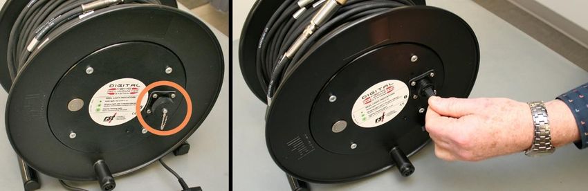
MEMS Digital Inclinometer System with
                                                                                    Android
                                                                         Instruction Manual

                                        REVISION HISTORY

Rev.                     Revision History            Date        Prepared By   Approved By

  A    Initial release                             2021-Mar-15       DH             AB

ICM0099A                                                                                  i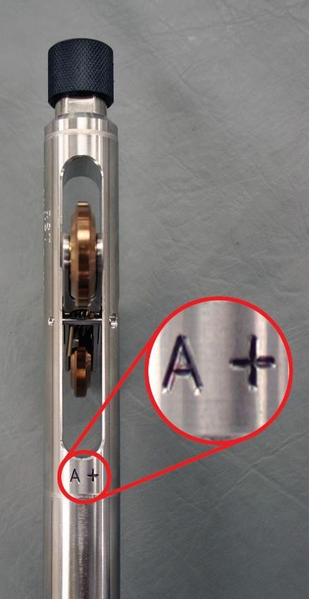
MEMS Digital Inclinometer System with Android
                                                                                          Instruction Manual

                                                TABLE OF CONTENTS
1   INTRODUCTION ............................................................................................................ 1
2   DIGITAL PROBE ........................................................................................................... 3
         DUMMY PROBE ...................................................................................................... 4
         SIGN CONVENTION AND MEASURED DEVIATION ........................................................ 4
         TAKING READINGS ................................................................................................. 7
3   INCLINOMETER CABLE AND REEL.................................................................................. 9
         INCLINOMETER REEL BATTERY .............................................................................. 10
         CHARGING THE BATTERY (FOR REELS WITH SERIAL NUMBER OF 2500 OR HIGHER) .... 11
         WIRELESS COMMUNICATION ................................................................................. 11
4   ANDROID DIGITAL INCLINOMETER APP ........................................................................ 12
        REQUIREMENTS ................................................................................................... 12
        DEVICE RECOMMENDATIONS ................................................................................ 12
    4.2.1 SAMSUNG GALAXY TAB ACTIVE 2 .................................................................... 13
    4.2.2 JUNIPER MESA3 ............................................................................................ 14
    4.2.3 JUNIPER CP3 ................................................................................................ 15
        DIGITAL INCLINOMETER APP WORKFLOW ............................................................... 16
    4.3.1 INSTALL OR UPDATE THE APP ......................................................................... 16
    4.3.2 ANDROID SETTINGS PRE-REQUISITES .............................................................. 16
    4.3.3 APP USER INTERFACE ORGANIZATION ............................................................. 17
    4.3.4 WORKFLOW OVERVIEW .................................................................................. 18
    4.3.5 VIEW SITE LIST .............................................................................................. 19
    4.3.6 VIEW BOREHOLE LIST .................................................................................... 20
    4.3.7 VIEW READINGS LIST ..................................................................................... 21
    4.3.8 VIEW READINGS LIST - COMPARISON GRAPH ................................................... 21
    4.3.9 ADD READINGS .............................................................................................. 23
    4.3.10 ADD READINGS – DELETE AND CONFIGURE ................................................... 26
    4.3.11 ADD READINGS - DATA AND GRAPH .............................................................. 27
    4.3.12 EXPORT READING FILES OVERVIEW .............................................................. 28
    4.3.13 EXPORT READING FILES TO ANDROID DEVICE (INTERNAL STORAGE) ............... 29
    4.3.14 EXPORT READING FILES TO EMAIL RECIPIENTS .............................................. 29
    4.3.15 IMPORT READING FILES OVERVIEW ............................................................... 30
    4.3.16 IMPORT FILES FROM ANDROID INTERNAL STORAGE ....................................... 30
    4.3.17 IMPORT ZIP FILE FROM STORAGE ................................................................ 31
    4.3.18 REEL AND PROBE STATUS ........................................................................... 31
    4.3.19 DEVICES LIST ............................................................................................. 32
    4.3.20 REEL AND PROBE INFORMATION .................................................................. 32
5   PROBE TYPES ........................................................................................................... 33
         VERTICAL PROBE ................................................................................................. 33
         HORIZONTAL PROBE ............................................................................................ 33
         INCLINE PROBE .................................................................................................... 34
         COMPASS PROBE ................................................................................................ 34

ICM0099A                                                                                                                    ii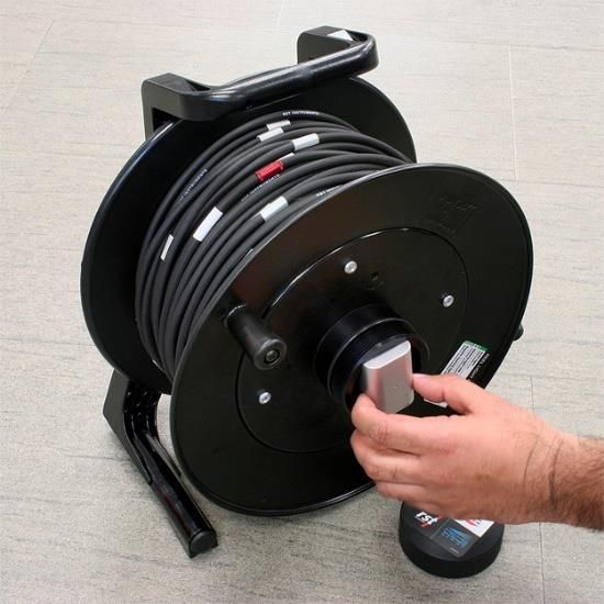
MEMS Digital Inclinometer System with Android
                                                                                           Instruction Manual

          SPIRAL PROBE .................................................................................................... 34
6    WHAT DOES THE DATA MEAN?.................................................................................. 34
          CHECKSUMS........................................................................................................ 34
          MEAN DEVIATION ................................................................................................. 35
          ABSOLUTE POSITION ............................................................................................ 35
          INCREMENTAL DISPLACEMENT .............................................................................. 35
          CUMULATIVE DISPLACEMENT ................................................................................ 35
7    SYSTEM COMPATIBILITY ............................................................................................. 35
8    CARE AND MAINTENANCE .......................................................................................... 36
          PROBE & REEL CONNECTORS .............................................................................. 36
          INCLINOMETER PROBE ......................................................................................... 37
          REEL AND CABLE ................................................................................................. 37
          ANDROID DEVICE ................................................................................................. 38
          CALIBRATION ....................................................................................................... 38
9    IMPORTING AND EXPORTING FILES .............................................................................. 38
          SAVING AND IMPORTING INCLINOMETER DATA INTO DIGIPRO SOFTWARE ................. 38
          USING SLOPE INDICATOR DATA WITH INCLINALYSIS ................................................ 38
          IMPORTING INCLINOMETER DATA INTO GTILT ......................................................... 38
10     SYSTEM SPECIFICATIONS ........................................................................................ 40
11     TROUBLESHOOTING ................................................................................................ 40
APPENDIX A           CHANGING THE BATTERY (FOR REELS WITH SERIAL NUMBERS UNDER 2500) 43
APPENDIX B           ANDROID TIPS ......................................................................................... 46
               B-1.    INSTALLING THE DIGITAL INCLINOMETER APP FROM THE GOOGLE PLAY STORE ..46
               B-2.    INSTALLING THE DIGITAL INCLINOMETER APP APK FROM LOCAL STORAGE ........46
               B-3.    CONNECTING THE USB FOR FILE TRANSFER MODE .........................................46
               B-4.    UNINSTALLING THE DIGITAL INCLINOMETER APP ...............................................46
               B-5.    DELETING THE APPLICATION DATA...................................................................47
               B-6.    CONFIGURING DISPLAY OPTIONS.....................................................................47
               B-7.    CONFIGURING SOUND OPTIONS ......................................................................47
               B-8.    TOUCH PANEL CONTROL OPTIONS ..................................................................48

ICM0099A                                                                                                                    iii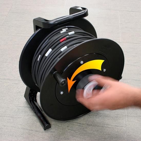
MEMS Digital Inclinometer System with Android
                                                                                               Instruction Manual

                                                    LIST OF FIGURES

Figure 1 – System Overview ...................................................................................................... 2
Figure 2 – Digital Probe Sizing ................................................................................................... 3
Figure 3 – Probe Orientation ...................................................................................................... 5
Figure 4 – Sign Convention in the A-axis and Deviation D measured by inclinometer probe ...... 6
Figure 5 – Probe Axes ............................................................................................................... 6
Figure 6 – A+ Marking on the Inclinometer Probe ...................................................................... 7
Figure 7 – Unscrewing the Battery Cap .....................................................................................11
Figure 8 – Samsung Active2 tablet............................................................................................13
Figure 9 – Juniper Mesa3 tablet ................................................................................................14
Figure 10 – Juniper CP3 smartphone........................................................................................15
Figure 11 – Digital Inclinometer App Icon ..................................................................................16
Figure 12 – Screen Organization ..............................................................................................17
Figure 13 – Workflow Overview Hierarchy ................................................................................19
Figure 14 – Sample site list .......................................................................................................19
Figure 15 – Sample borehole list ...............................................................................................20
Figure 16 – Sample reading list and comparison graph.............................................................21
Figure 17 – Select the base reading..........................................................................................22
Figure 18 – Select the comparison reading(s) ...........................................................................22
Figure 19 – Axis A+ reading at bottom depth (10m) and top depth (0.5m) ................................24
Figure 20 – Axis A- reading bottom depth (10m) and top depth (0.5m) .....................................25
Figure 21 – Delete reading ........................................................................................................26
Figure 22 – Modify reading option .............................................................................................27
Figure 23 – Sample Axis A+ and Axis A- reading ......................................................................27
Figure 24 – Sample Absolute, Mean Deviation and Checksum plots.........................................28
Figure 25 – Export Screen ........................................................................................................29
Figure 26 – Export via email......................................................................................................30
Figure 27 – Communication status between the App and Reel/Probe/Battery ...........................31
Figure 28 – Sample devices list ................................................................................................32
Figure 29 – Reel and probe information ....................................................................................33
Figure 42 – Battery Removal / Installation .................................................................................43
Figure 43 – Standby Mode ........................................................................................................43
Figure 44 – Initial Charge ..........................................................................................................44
Figure 45 – MED Charge ..........................................................................................................44
Figure 46 – HI Charge...............................................................................................................44
Figure 47 – MAX Charge ..........................................................................................................44
Figure 48 – Error in Charging ....................................................................................................45

 ICM0099A                                                                                                                          iv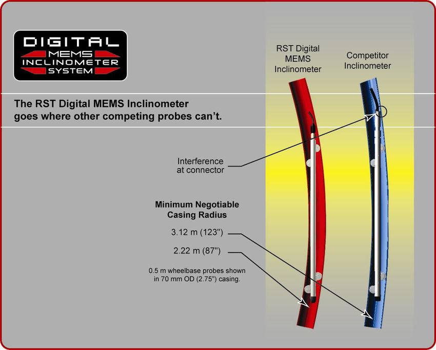
MEMS Digital Inclinometer System with Android
                                                                                       Instruction Manual

1         INTRODUCTION
    The RST MEMS Digital Inclinometer System represents a breakthrough in inclinometer
    system technology, providing unprecedented accuracy, efficiency and ease of use. The
    system is comprised of a Digital Inclinometer Probe, cable system, reel with battery power,
    and an Ultra-Rugged Field PC running Mobile Microsoft Windows™ that functions as a
    readout, analysis, and data storage device.
    Wireless communication between the inclinometer control reel and the Ultra-Rugged Field
    PC ensures ease of use and reliability, by removing two weaknesses inherent in
    conventional analog inclinometer systems. By removing the physical connection between
    the inclinometer control cable and the readout instrument there is no concern with fragile
    connectors, cable related failure and related reliability problems. The Achilles heel of any
    inclinometer control cable reel is the slip ring required to maintain electrical contact as the
    reel revolves. As the RST system is wireless from the control cable to the readout, a slip
    ring is not required, and there are no associated electrical continuity problems.
    The RST digital inclinometer probe incorporates cutting edge MEMS (Micro Electro-
    Mechanical Systems) technology providing high precision and durability. A highly accurate
    survey of the inclinometer casing is used to establish the initial position of the casing. Any
    subsequent deviations in the casing from this initial value (i.e. baseline reading) represent
    changes occurring in the subsurface. The RST MEMS Digital Inclinometer System can
    accurately measure the rate, depth, and magnitude of these deviations.
    The information included in this manual outlines the use and care of the RST MEMS Digital
    Inclinometer System. It provides examples of how to take readings and interpret the data.
    For more information on the installation of inclinometer casing, and other related issues,
    please contact RST Instruments Ltd.
                                                        Note
      Proper care and maintenance of the MEMS Digital Inclinometer System will greatly
      extend the life of the instrument and accuracy of the readings. Please take the time to
      read this manual thoroughly. If any questions arise, do not hesitate to contact RST
      Instruments Ltd. Proper maintenance of the probe after each use is outlined in Section
      12 .
      X       X

    Functions:
          •       Measure lateral movement of:
                      o   Earthworks or structures
                      o   Landslides
                      o   Embankment fills
          •       Stability adjacent to excavations or underground workings
          •       Deflection of piles, piers, abutments or retaining walls

ICM0099A                                                                                              1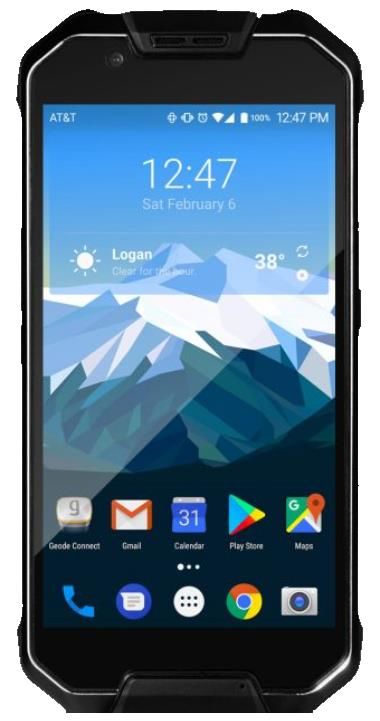
MEMS Digital Inclinometer System with Android
Instruction Manual
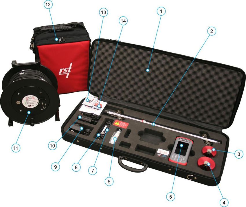
Figure 1 – System Overview
1. Soft Shell Case
2. Digital Inclinometer Probe (w/ protective end cap)
3. 70mm/2.75” OD Cable Grip
4. 85mm/3.34” OD Cable Grip
5. Android Device
6. Silicone Lubricant (for use on connectors)
7. Device Accessories
8. USB Cable for Android Device
9. AC Adapter for Android Device
10. AC Adapter for Reel Battery Charger
11. Cable Reel with Wireless Communication System
12. Reel Carrying Case
13. Micro-fiber cleaning Cloth
14. Software Installation DVD
ICM0099A 2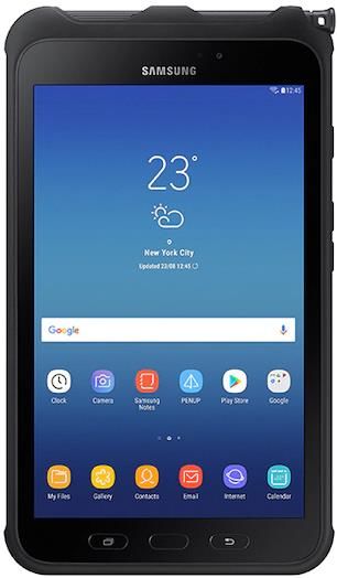
MEMS Digital Inclinometer System with Android
                                                                                Instruction Manual

2       DIGITAL PROBE
    In general terms, the new Digital Probe resembles that of the traditional analog probes sold
    by RST. The RST Digital Inclinometer has the smallest package available for a given wheel
    spacing, with the best ability to track deformed casings. This means that the Digital Probe
    can handle greater bends in the casing without becoming stuck. The RST metric probe can
    negotiate a radius of 1.88m (74”) in 70mm (2.75”) OD inclinometer casing. The RST Digital
    Inclinometer will thus continue to provide readings past the limit for other probes on the
    market (see Figure 2 ).
                X        X

                             Figure 2 – Digital Probe Sizing
    The connectors, wheels, and wheel carriages are the most precise and durable in the
    industry. The probe wheels are made of high grade hardened and heat-treated stainless
    steel. These are extremely durable and the most robust on the market.
    The digital probe also incorporates shear pins on the wheel assemblies. In the event that
    the probe gets stuck in the inclinometer casing, a force of approximately 300 lbs is required
    to shear the shear pin. No damage to the probe or cable will result. Please contact RST
    Instruments Ltd. for further instructions on retrieval of a probe that is stuck
    downhole, and the replacement of the probe shear pins.

ICM0099A                                                                                        3
MEMS Digital Inclinometer System with Android
                                                                               Instruction Manual

      DUMMY PROBE
  Dummy inclinometer probes are available for purchase from RST for testing purposes in a
  borehole. RST encourages customers to try the new digital dummy probe in existing holes
  where the competitor’s probes do not work. If it is found that the dummy probe passes
  through all areas of the casing, the RST MEMS Digital Inclinometer System will function.
  Therefore, the existing hole will still be viable, and a new hole will not need to be drilled.
  The RST dummy probe has the exact same weight and dimensions as the standard probe.
  A ring is provided in place of the connector which allows the dummy probe to be lowered by
  a rope. For further information on purchasing a RST Dummy Probe, please contact RST
  Instruments Ltd.

      SIGN CONVENTION AND MEASURED DEVIATION
  The Digital Inclinometer Probe houses two MEMS accelerometers, which measure tilt in two
  axes. Proper installation of the inclinometer casing attempts to align one set of grooves in
  line with the axis of expected movement. This is called the A axis. The perpendicular set of
  grooves is the B axis.
  When an inclinometer casing is surveyed for the first time (i.e. baseline readings), it is
  necessary to select a fixed direction reference for the probe so that each time a survey is
  repeated, the probe will always have the same orientation in the casing.
  For example, in an area suspected of landslide activity, the first set of readings would be
  taken by placing the upper wheels of the probe in the casing groove closest aligned to the
  downslope direction. Figure 3 illustrates an inclinometer casing installed with a groove
                        X       X

  orientation in the general downslope direction.
  In practice, it is often difficult to achieve exact orientation of grooves relative to some
  predetermined direction. The groove closest to the anticipated movement direction is usually
  chosen as the main reference direction. It is recommended that this direction (A+) be
  marked on the casing itself to ensure surveys are performed in the same manner each time.
  The azimuth of this groove direction can be measured in a clockwise direction from the main
  reference direction (A+). All subsequent measured inclinometer movements would be
  referred to this direction.
  Readings taken from the inclinometer probe (see Section 2.3) are actually deviations from
  the vertical over the distance between the upper and lower wheels (see Figure 4), calculated
  as:

                                       D = L × sine(α)
  Where:     D = Deviation, e.g. lateral displacement in the direction of the axis of
             measurement
             L = inclinometer probe length (typically 0.5 m for a metric probe or 2 ft for an
             imperial probe, as defined in Section 10).
             α = inclination angle of probe from vertical axis

ICM0099A                                                                                        4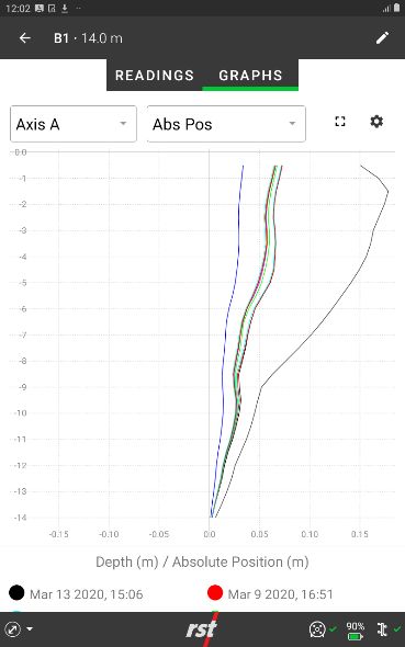
MEMS Digital Inclinometer System with Android
                                                                                 Instruction Manual

                             Figure 3 – Probe Orientation
  The RST Digital Inclinometer System uses the industry standard sign convention, where tilt
  in the direction of the upper wheels results in a positive deviation and tilt in the direction of
  the lower wheels results in a negative deviation ( Figure 4 ).
                                                     X         X

ICM0099A                                                                                          5
MEMS Digital Inclinometer System with Android
Instruction Manual
Figure 4 – Sign Convention in the A-axis and Deviation D measured by
inclinometer probe
X Figure 5 shows the sign convention for the A and B axis.
X
B- B+ A- A+
UPPER WHEEL UPPER
BEHIND PROBE WHEEL
Figure 5 – Probe Axes
ICM0099A 6MEMS Digital Inclinometer System with Android
Instruction Manual
Figure 6 – A+ Marking on the Inclinometer Probe
TAKING READINGS
1. Upon arrival at the site, remove the protective caps from the casing, the probe, and
the control cable. If possible, flush the borehole with clean water prior to taking
measurements. Groundwater with high salinity or suspended particulate
content can damage the bearings in the probe wheels with repeated use.
2. Attach the probe to the reel by aligning the keyways and threading the connector
onto the probe. Ensure the connector is lubricated, clean, and free of debris
prior to making the connection. Take care to turn only the threaded ring, not the
cable itself. Do not over tighten the connector; a hand tight connection is sufficient.
Warning
Handle the inclinometer probe very carefully as the accelerometers are very
susceptible to shock.
3. Once connected, turn on the power to the reel. This energizes the MEMS
accelerometers and makes them less susceptible to shock.
4. Insert the probe into the borehole, aligning the upper wheel in the direction of the A+
axis (see Section 2.2 ).
X X
5. Lower the probe to the desired depth slowly and as smoothly as possible. Be
extremely careful not to bounce the probe off the bottom of the hole. Any
shock to the probe may damage the probe electronics and affect its
calibration.
ICM0099A 7MEMS Digital Inclinometer System with Android
Instruction Manual
6. Once the probe is at the desired depth, place the cable grip on the top of the casing
and hang the cable by the aluminum crimps. The objective is placement
repeatability within 5mm (0.25 inch). This is extremely important to ensure accurate
and repeatable results.
Warning
Do not drop the cable aluminum crimps onto the cable grip. The cable has very
little stretch, especially near the top of hole, and the impact on the cable crimps
may “hammer” them out of position or break the cable. This effect has been
demonstrated for drops as little at 70 mm.
7. The probe will begin profiling the borehole from the bottom of the borehole. After
each respective measurement has stabilized and a recording has been taken, pull
the probe upwards to the next desired measurement depth. If you accidentally pull
the probe too far, lower the probe back down to the previous measurement depth,
and then pull it back to the next intended measurement depth. This procedure
ensures that the readings will remain consistent. For maximum measurement
repeatability, keep the cable as clean as possible during this process. If possible, a
tarp or basket can be useful to avoid placing the cable directly on the ground.
Warning
Never tightly coil or sharply bend the cable during this process, as this can cause
permanent coiling or twisting of the cable which can impact the spacing of the
aluminum crimps and measurement repeatability. It is recommended to lay the
cable in a “figure-8” or “spaghetti bowl” pattern as follows:
a. “Figure-8” Cable Management: As the probe is brought up-hole, lay the
excess cable on a clean surface in alternating loops to form a figure-8 pattern.
The loops of the figure-8 should be approximately the size of the cable reel
diameter. Once the survey is complete, flip over the bundled figure-8 of cable
for easy spooling back onto the reel.
b. “Spaghetti Bowl” Cable Management: As the probe is brought up-hole, allow
the cable to freely coil as it is laid on a clean surface. Do not attempt to twist
or coil the cable, as this can deform the cable with repeated use.
8. Allow the readings to stabilize at each location. Reading stability can be gauged by
both the noise bar and the standard deviation, which are displayed on the Readings
List (Section 4.3.7).
9. Once the readings have stabilized, press the Accept button and move the probe to
the next interval as prompted by the software.
10. Repeat Steps 7-9 until the probe reaches the top of the borehole. The App will then
prompt you to turn the probe 180 degrees and repeat the survey, this time in the A-
direction (i.e. with the lower probe wheels in the A+ groove).
Warning
When the probe has reached the top of the casing, avoid allowing the wheel
assemblies to snap out of the casing. As the wheels reach the top, grasp them
with your hand and release the wheel assembly slowly until it reaches the stops.
Failure to do so will damage the shear pin and subject the MEMS
accelerometers to sudden shock, which can damage them and affect the
calibration of the probe.
ICM0099A 8MEMS Digital Inclinometer System with Android
Instruction Manual
11. Prior to lowering the probe for the second pass, remove the cable grip to avoid
accidentally catching the aluminum crimps on the cable grip (this will impact load the
crimps, cable, and probe). Once the probe is at the bottom of the borehole, replace
the cable grip and position the probe for the deepest reading.
12. Repeat Steps 7-9 to take a second pass of readings in the A- direction. During this
second pass, checksum data will be displayed underneath each reading. Ensure
that these remain small and consistent; however, checksums can vary due to
different site conditions. Large checksums can indicate errors in probe positioning or
fouling of the probe. Expect checksums to be slightly larger when the probe
encounters an expansion coupling in the casing (if applicable). Refer to Section 6
for further detail on checksums.
13. The RST MEMS Digital Inclinometer has the ability to perform data reduction in the
field, please refer to Section 4.2.8 for information on viewing and validating the data.
X X
14. Upon completion of the survey, close the inclinometer app, turn off the power to the
reel, and disconnect the probe. Wipe off the probe and cable. If possible, rinse the
probe and cable with fresh water. Replace end caps on the cable and probe.
Replace the protective cap on the casing.
15. Upon returning to the office, clean the instrument and reel once more to remove any
moisture from the instruments and the case. Recharge the batteries for the Reel
and the Android data collection device. Please refer to Section 8 for proper care
and maintenance of the system.
16. If required, transfer the collected data files via email or file transfer.
3 INCLINOMETER CABLE AND REEL
The RST MEMS Digital Inclinometer System comes with a durable lightweight reel that is
easy to handle. Since only a pair of conductors is needed in the cable, the weight and
dimensions of the cable are drastically reduced as compared to a traditional analog cable.
The reel is battery powered and houses the electronics used for wireless communication.
An important part to any inclinometer casing survey is the repeatability of the depth
measurements. It is extremely important that measurements be consistently within 5mm
(0.25”) of one another between subsequent surveys. To facilitate accurate repeatability, two
aluminum cable grips are provided with the system, for 70mm (2.75”) and 85mm (3.34”) OD
casing respectively. The cable grips provide a solid reference for the cable crimps to sit in.
The result is that operator error is reduced, checksums will be smaller and surveys more
accurate.
The thin, strong cable contains a Kevlar® strength member, allowing a long length of cable
to fit on a small reel with no stretch. The aluminum sleeved measure marks are precision
swaged to the cable and are not subject to tearing when handling. The measure marks are
spaced at 0.5 metre or 2 feet intervals. The cable is marked with a red measure mark and a
label every 5 metres or 10 feet, depending on whether the metric or imperial system is being
used. The urethane jacket is highly abrasion resistant and maintains flexibility at low
temperatures. It is good practice to avoid running the cable over sharp edges and to
periodically clean it with a soft clean cloth. Be sure to keep the protective cap on the
connector whenever the probe is not in use and avoid dropping or banging the cable end.
Always keep the connectors and threads clean by rinsing them with water and be sure to
lubricate frequently. Exercise care when connecting and removing the cable from the probe;
make sure to only turn the connector ring, not the entire cable.
ICM0099A 9MEMS Digital Inclinometer System with Android
Instruction Manual
INCLINOMETER REEL BATTERY
If the serial number of the reel is 2500 or above, the battery is contained inside the
inclinometer reel. The inside of the reel is not accessible to the user and the battery is not
removable. Do not attempt to remove the battery.
The inclinometer reel has a green LED light that will flash to indicate battery status (Table 1).
The LED light on the reel will flash when the power button is pressed.
Monitor the battery status. Do not let the battery completely discharge. A full charge will
last around 30 hours.
Note
For reels with serial numbers under 2500, refer to Appendix A for instructions on how to
remove and recharge the battery. Only batteries on reels with serial numbers under 2500
may be removed from the reel. Do not attempt to remove the battery from the reel if the
serial number on the reel is 2500 or higher.
For reels with serial numbers of 2500 or higher, refer to Section 3.1 for battery status and
Section 3.2 for instructions on how to recharge the battery. Only reels with a serial number of
2500 or higher may be recharged. Do not attempt to remove the battery from the reel if the
serial number of the reel is 2500 or higher.
ICM0099A 10MEMS Digital Inclinometer System with Android
Instruction Manual
Table 1 Battery status LED
LED Flash Battery Status
1 flash, reel does not power on Battery completely discharged
2 flashes, reel does not power on Battery discharged below level required to connect
1 flash, reel powers on Battery discharged below 25%
2 flashes, reel powers on Battery discharged below 50%
3 flashes, reel powers on Battery discharged below 75%
4 flashes, reel powers on Battery is at full charge.
CHARGING THE BATTERY (FOR REELS WITH SERIAL NUMBER OF
2500 OR HIGHER)
Note
Refer to Appendix A if the reel serial number is under 2500. Do not proceed with the
following instructions if the reel serial number is under 2500.
The following instructions are for reels with serial numbers of 2500 or higher.
The battery will need to be recharged using the provided charger. The battery port may be
accessed by unscrewing the cap on the outside of the reel. Refer to Figure 7 for the location
of the battery cap.
Figure 7 – Unscrewing the Battery Cap
Unscrew the battery cap by turning it counter clockwise. The charger will plug into the port
and begin charging the battery. Replace and tighten the cap when the charger is not in use
to ensure debris does not enter the battery port.
WIRELESS COMMUNICATION
Turn on the power to the reel by pressing the button located to the left of the battery housing
on the Reel Hub (Figure 7). A solid green light indicates the reel has been powered on.
After turning on the power to the reel, it automatically broadcasts its device name and will
continue to broadcast for up to 5 minutes. During this 5-minute window, the Digital
Inclinometer app must establish a Bluetooth connection with the reel. If the Reel Hub is
unable to connect to the Digital Inclinometer app, the Reel Hub powers down to reduce
battery consumption.
ICM0099A 11MEMS Digital Inclinometer System with Android
Instruction Manual
The Reel Hub reset button is equipped with a green light status indicator, The status light
indicates that the Reel is in one of the following three states:
• Off – the Reel Hub is powered off.
• On – the Reel Hub is powered up, but not connected to the Digital Inclinometer app.
• Blinking at 1-second intervals – the Reel Hub is connected to the Digital
Inclinometer app.
4 ANDROID DIGITAL INCLINOMETER APP
The RST MEMS Digital Inclinometer System app runs on most Android devices running
Android 5.1 and higher. The Android device functions as a readout and data storage device.
Data reduction can be performed on site as soon as the survey is complete. The app is
equipped with data visualization features to qualify data accuracy.
REQUIREMENTS
The Digital Inclinometer app can run on Android device with Android 5.1 and higher. The
device should be Google Mobile Services certified and be pre-installed with apps such as
Google Play and Google Gmail.
The Android device must be equipped with a Bluetooth classic capability to support wireless
connectivity with the legacy and latest generation inclinometer systems.
Other wireless networking capabilities such as Wi-Fi and Cellular are recommended for
remotely updating data collection files over email services.
DEVICE RECOMMENDATIONS
The process of collecting data at the borehole is a demanding task. The device is often
subjected to harsh environmental and field conditions. Due to these considerations, RST
recommends only rugged Android devices that can withstand the daily rigours encountered
in the harshest environment, such as the Samsung Galaxy Active 2, the Juniper Mesa3, and
Juniper CP3 smartphone/tablets.
ICM0099A 12MEMS Digital Inclinometer System with Android
Instruction Manual
4.2.1 SAMSUNG GALAXY TAB ACTIVE 2
Figure 8 – Samsung Active2 tablet
Table 2 Samsung Active2 Feature Highlights
Model Samsung Galaxy Tab Active 2
Operating System Android 9
CPU 1.6 GHz, Octa Core
Memory 3 GB
Display / Resolution 8.0” / (1280 x 800)
Wi-Fi 802.11 a/b/g/n/ac
Bluetooth V 4.2
Cellular 4G LTE
Battery Capacity / Usage 4450 mAh / 11 Hours
Physical (width, length, depth) 127 x 215 x 10 mm, 5.0 x 8.5 x 0.4 inches
Weight 0.42 kg, 1.0 lbs
Operating Temperature -20 to +50 C, -4 to 122 F
Ingress Protection IP68 waterproof and dustproof
Cellular 4G LTE
Certification MIL-STD-810G
ICM0099A 13MEMS Digital Inclinometer System with Android
Instruction Manual
4.2.2 JUNIPER MESA3
Figure 9 – Juniper Mesa3 tablet
Table 3 Juniper Mesa3 feature highlights
Model Juniper Mesa3
Operating System Android 9
CPU 1.6 GHz, Octa Core
Memory 6 GB
Display / Resolution 7.0” / (1280 x 800)
Wi-Fi 802.11 a/b/g/n/ac
Bluetooth V 5.0
Cellular 4G LTE
Battery Capacity / Usage 43.2 Whr / 10-12 Hours
Physical (width, length, depth) 137 x 215 x 35 mm, 5.40 x 8.48 x 1.36 inches
Weight 0.70 – 0.90 kg, 1.5 – 2.0 lbs
Operating Temperature -20 to +50 C, -4 to 122 F
Ingress Protection IP68 waterproof and dustproof
Certification MIL-STD-810G
ICM0099A 14MEMS Digital Inclinometer System with Android
Instruction Manual
4.2.3 JUNIPER CP3
Figure 10 – Juniper CP3 smartphone
Table 4 Juniper CP3 feature highlights
Model Juniper CP3
Operating System Android 7
CPU Snapdragon 653 Octa-core
Memory 6 GB
Display / Resolution 5.5” / (1920 x 1080)
Wi-Fi 802.11 a/b/g/n
Bluetooth V4.0 BLE
Cellular 4G LTE (Bands 2, 4, 5, 7, 12, 17)
Battery Capacity / Usage 6000 mAh
Physical (width, length, depth) 168 x 83 x 14 mm, 6.6 x 3.3 x 0.55 inches
Weight 0.25 kg, 0.55 lbs
Operating Temperature -30 to +60 C, -22 to 140 F
Ingress Protection IP68 waterproof and dustproof
Certification MIL-STD-810G (Shock and Drop)
ICM0099A 15MEMS Digital Inclinometer System with Android
Instruction Manual
DIGITAL INCLINOMETER APP WORKFLOW
4.3.1 INSTALL OR UPDATE THE APP
The RST Digital Inclinometer app is available for download from the Google Play Store.
Installation and updated information is fast, easy, and secure. To find the RST app, search
the keywords “RST Inclinometer” to immediately access all the information on the app.
If the app is already installed on the device, updates are also available from the Google Play
Store. The RST Digital Inclinometer app is always designed with compatibility in mind; app
updates maintain all historical accumulated data.
Once the Digital Inclinometer app is installed, its icon and app name should be visible on the
Android app listing. The app icon is shown in Figure 11.
Figure 11 – Digital Inclinometer App Icon
This manual details the user experience for the Digital Inclinometer app, version 1.1.0 and
higher.
4.3.2 ANDROID SETTINGS PRE-REQUISITES
The Digital Inclinometer app requires several custom settings to maximize the user
experience. The following configurations should be customized to access the services:
• Internet Access – internet access via Wi-Fi, cellular, or both, is required to allow the
app to email collected borehole data to a recipient. Email is one of the available
mechanisms to transfer collected borehole data from the device to another
computer.
• Voice Call or Text Messaging – the Digital Inclinometer app has capability to call a
contact person. If this feature is required, an activated voice SIM card must be
inserted and configured.
• Gmail Account Setup on the Device – a Google Gmail account on the device is
recommended. The Digital Inclinometer app uses the Gmail account on the device
to send collected borehole data to an email recipient.
• Font Size and Screen Zoom Settings – the default font size and screen zoom on the
device are two settings that affects the appearance and layout of the app.
Selecting an inappropriate font size and zoom setting may result in truncation of
words and excessive word wrap. To avoid these problems, adjust the Android font
size and style accordingly to a desirable setting. The font size and zoom setting are
configurations available in the Settings→Display category.
It is recommended that the user configure the device with the smallest font size and
zoom setting as an initial setting, increasing the font size and zoom setting
incrementally to the desired appearance.
• Screen Timeout – the screen timeout should be set to a large timeout value, such as
30 minutes. The timeout specifies the time before the devices enters sleep mode.
ICM0099A 16MEMS Digital Inclinometer System with Android
Instruction Manual
• Date and Time Setting – ensure that the date and time information is correct, as the
Digital Inclinometer app embeds the date and time information into the reading data.
4.3.3 APP USER INTERFACE ORGANIZATION
The Digital Inclinometer app is specifically designed to simplify the user workflow. The
organization of the screen is designed to allow the user to access all functions with a
minimal number of touches.
The screen layout of the app is always oriented in a portrait mode to maximize the display of
scrollable lists and graphical plots.
The screen layout contains three primary regions:
• Top title bar - the title reflects the context-sensitive content. Additional controls, if
applicable, are located at the left or right corner.
• Context specific content.
• Bottom status bar - this area displays the current connection status of the reel,
probe, and non-context specific content.
The user interface organization is shown in Figure 12.
Figure 12 – Screen Organization
The Digital Inclinometer app utilizes commonly recognizable icons to enrich the digital
experience. Icons are positioned in different regions to provide context sensitive
functionality. Table 5 below details the user accessible icons and associated functionality in
the different regions.
ICM0099A 17MEMS Digital Inclinometer System with Android
Instruction Manual
Table 5 Icon definitions
Top Title Bar Icons
Icon Short Name Description
Close Close current configuration without saving
Back Return to the previous screen
More View more options
Edit Edit configuration
Delete Delete entry
Context Specific Content Icons
Icon Short Name Description
Zoom out Display graphs in full screen mode
Zoom In Display graphs in partial screen mode
Configuration Configure graph options
Info Display information on the reel and probe
Bottom Status Bar Icons
Icon Short Name Description
Measure Display Measurement operational mode
Devices Display Reel and Probe information mode
Transfer Import/Export
Help Display Help functions
Probe Probe is not available
Disconnected
Probe Probe is connected and is providing measurement data
Connected
Reel Reel is disconnected from the Bluetooth interface
Disconnected
Reel Reel is connected to the Bluetooth interface
Connected
Battery Reel Battery level
4.3.4 WORKFLOW OVERVIEW
The Digital Inclinometer app workflow is presented in a logical hierarchy. The hierarchy
consists of four primary functional categories. From the primary categories, the user may
access context-specific features. The four primary functional categories, as shown in Figure
13, are:
• View Site List – a list of all the created sites.
• View Borehole Lists – a list of all created borehole for a selected site.
• View Readings List – a list of all collected readings for a selected borehole.
ICM0099A 18MEMS Digital Inclinometer System with Android
Instruction Manual
• View Single Reading – a list of the depth measurements and plot options for a selected
reading.
Figure 13 – Workflow Overview Hierarchy
4.3.5 VIEW SITE LIST
The View Site List is at the top of the workflow screen. The View Site List displays a listing of
the available sites sorted based on the site creation date. Each site shows the site name,
company name, and site creation time.
Tap on a desired site to view the borehole lists associated with the selected site.
A sample site list is shown in Figure 14.
Figure 14 – Sample site list
Tap the + NEW SITE button to create a new site. A site is created by entering and saving
the following information:
• Site Name (Mandatory) – name of the site,
• Client Company Name – name of the client’s company,
• Contact on Site – name of the contact person, and
• Contact’s Phone Number – phone number.
ICM0099A 19MEMS Digital Inclinometer System with Android
Instruction Manual
4.3.6 VIEW BOREHOLE LIST
The View Borehole List is displayed when the user selects a particular site from the View
Site List screen. The View Borehole List displays a listing of the available boreholes sorted
based on the borehole creation date. Each borehole shows the borehole name, and the
depth of the borehole.
Tap on a desired borehole to view the borehole readings associated with the selected
borehole.
The user may also tap the More icon to call the contact person’s phone number or edit the
site information.
The user may also tap the + NEW BOREHOLE button to create a new borehole. A borehole
is created by entering the following information:
• Borehole Name (Mandatory) – Name of the borehole
• Depth – Depth of the borehole’s lowest reading. The depth will always be in
increments of 0.5 meters or 2.0 ft.
• Top Depth – Depth of the borehole’s top reading. This is normally set to 0.5 meters
or 2.0 ft.
• Unit – Measurement is taken in meters or feet based and must match the probe’s
units.
• Export Format – The collected reading file may be supported in two industry formats.
The two formats are:
▪ Digital Inclinometer (*.csv) format: this type of file can be imported into
Inclinalysis™ and Microsoft Excel.
▪ RPP Format (*.rpp): this type of file can be imported into Inclinalysis™,
DigiPro and Slope Indicator’s software including DMM for Windows. GTilt
and GTilt Plus software also has the ability to import *.rpp file formats.
A sample borehole list is shown in Figure 15.
Figure 15 – Sample borehole list
ICM0099A 20MEMS Digital Inclinometer System with Android
Instruction Manual
4.3.7 VIEW READINGS LIST
The View Readings List is displayed when the user selects a particular borehole from the
View Borehole List screen. The View Reading List displays a listing of readings taken from
the borehole sorted based on the borehole reading timestamp.
Each reading shows the reading completion date and time. If the reading were incomplete,
the reading status displays “Incomplete”. The user may resume taking readings from an
incomplete reading.
The user may also tap the edit icon to edit the borehole information.
The user may tap the Graphs tab to view the combined graphs of readings from the
borehole. A description of the combined graphing capability is detailed in Section 4.3.8.
The user may tap on a desired reading to view borehole readings taken on a specific date or
resume taking readings from a previously incomplete session.
The user may also tap the + ADD READINGS button to add a new reading. A description of
the Add Readings feature is detailed in Section 4.3.9.
A sample reading list is shown in Figure 16.
Figure 16 – Sample reading list and comparison graph
4.3.8 VIEW READINGS LIST - COMPARISON GRAPH
The Digital Inclinometer system has been developed to accurately measure the lateral
movement of earthworks and structures. The probe is passed through the inclinometer
casing and a reading is taken every 0.5m or 2ft. When the probe is at rest,
servo-accelerometers sense the inclination of the access tube in two planes. This inclination
is displayed in terms of angular DEVIATION, which is recorded at that particular depth.
A+ = Face A+ deviation
A- = Face A- deviation
B+ = Face B+ deviation
B- = Face B- deviation
The View Readings Comparison Graph feature combines the multiple readings from one
borehole and compares the result against a specific base reading. Typically, a base file is
chosen (typically in the form of an initial reading) and kept the same throughout the life of the
inclinometer hole in order to quantify any lateral displacement that occurred. The comparison
ICM0099A 21MEMS Digital Inclinometer System with Android
Instruction Manual
graphing feature allow the user to analyze results at the borehole and take appropriate
actions based on the collected results.
To utilize the comparison graphing feature, the user must first configure the desired data set
to review. The user must select the Base reading and the Comparison reading data sets.
Step 1 - Select the base reading
Tap the configuration icon to select the graph setting. Then tap the “Base reading” region to
list the possible base readings to choose. Select the desired base reading date as the base
or reference reading. This is shown in Figure 17.
Figure 17 – Select the base reading
Step 2 - Select the comparison reading(s)
Tap the configuration icon to select the graph setting. Then tap the “Show graphs for” region
to select or de-select the comparison readings. A listing of the historical readings are
displayed in chronological order. Select or de-select the desired readings to compare against
the base reading. This is shown in Figure 18.
Figure 18 – Select the comparison reading(s)
ICM0099A 22MEMS Digital Inclinometer System with Android
Instruction Manual
Step 3 - Select the desired graphs
Once the desired data set has been selected, the Digital Inclinometer app may plot 5
different types of comparison graphs for either Axis A or Axis B. The 5 comparison graphs
are:
• Checksum
• Mean Deviation
• Absolute Position
• Incremental Displacement
• Cumulative Displacement
Checksum
Checksum in A+/A- plane = A+ plus A-
Checksum in B+/B- plane = B+ plus B-
Checksum should be reasonably constant and of small magnitude; large and inconsistent
Checksums may indicate that a problem exists. However, the consistency of checksums
from survey to survey is more important than the actual value of the checksums. Checksum
data should be monitored during the survey as a check on data integrity. Note that high
checksums can be expected if a settlement coupling has been encountered, a checksum of
the order of (+0.0045m and -0.0035m) or (+0.0147ft and –0.0114ft) would be reasonable at
consecutive depths/couplings.
Mean Deviation
A+/A- mean deviation in the A+/A- plane = (A+ minus A-)/2
B+/B- mean deviation in the B+/B- plane = (B+ minus B-)/2
This represents the mean deviation at each depth.
Absolute Position
An absolute position value at a particular depth is the summation of mean deviations,
starting from the bottom up to that particular depth. The Absolute Position is the profile of the
access tube with respect to the vertical axis in a given plane. The Absolute Position can also
be calculated from the top down, if required, using Inclinalysis™ software.
Incremental Displacement
The Incremental Displacement is the difference in values of mean deviation between the
base file (i.e., the first set of readings taken) and a selected file(s) (usually the latest set of
readings) at each depth. This plot can be generated using Inclinalysis™ software.
Cumulative Displacement
The Cumulative Displacement value at a particular depth is the summation of incremental
displacements starting from the bottom up to that particular depth.
The profile represents the actual movement (or displacement) which has occurred at all
depths between the times that the two sets of readings were obtained.
4.3.9 ADD READINGS
The Digital Inclinometer app’s primary function is to take readings at the borehole. The “Take
Reading” feature commences when the user selects the Add Reading function from the View
Borehole Readings screen.
ICM0099A 23MEMS Digital Inclinometer System with Android
Instruction Manual
The Digital Inclinometer app first ensures the reel and probe are functional and
communicating with the app via Bluetooth. The Digital Inclinometer app then performs
integrity checks by verifying that the probe type is a vertical probe and the units in the probe
match the borehole units configuration. The user is notified of incorrect configurations and
prevented from taking readings.
If the integrity checks are correct and the reel/probe are successfully connected through
Bluetooth, the user may commence taking the displacement readings. The reading involves
measuring the Axis A+ depths followed by reading measuring the Axis A- depth after the
probe is rotated 180 degrees.
Axis A+ Take Readings Process – First Pass
The probe is first lowered to the lowest depth of the borehole. Once the probe is at the
correct depth and remains stationary, the real-time reading stabilizes.
The new readings screen shows the status of the probe readings refreshed approximately
once every second. Figure 19 shows a sample Axis A+ reading at the bottom depth and the
Axis A+ reading at the top depth.
Figure 19 – Axis A+ reading at bottom depth (10m) and top depth (0.5m)
Axis A and Axis B shows the instantaneous lateral displacement in meters or feet.
The Noise (uV) is the difference between the current reading and the previous reading
measured in microVolts. A small difference or noise level indicates a stable and accurate
reading. The noise level is color coded, where an optimal low noise level is displayed in
green, a marginal noise level is displayed in orange, and a high noise level is displayed in
red.
The noise level varies based on each borehole location. In noisy environments (i.e.,
locations with heavy equipment in the vicinity), the acceptance criteria for a reading may be
different based on environmental conditions.
If the user deems the probe reading is acceptable, the user taps the ACCEPT button. The
Digital Inclinometer app then repeats the process for the next depth.
If the user deems any of the previously accepted readings on the Axis A+ is improperly
taken, the user may request a re-take on any depth. The user lowers the probe to the re-take
depth. On the Digital Inclinometer app, the user scrolls to the depth and taps the RETAKE
ICM0099A 24MEMS Digital Inclinometer System with Android
Instruction Manual
ALL or RETAKE SINGLE button for that reading. The two retake options are defined as
follows:
• RETAKE ALL requires that the user retake all readings from the retake depth to the
top of the borehole.
• RETAKE SINGLE requires that the user retakes just the reading of the selected
depth and the app resumes from the current depth.
The user is prompted to confirm the re-take reading request.
Axis A- Take Readings Process – Second Pass
The depth reading continues until the probe reading reaches to the top depth. Once the top
of the hole has been reached, the Digital Inclinometer app prompts the user to turn the probe
180o and lower it back to the bottom of the hole. This is the Axis A- reading.
The Digital Inclinometer app starts the Axis A- depth at the lowest borehole depth. The Axis
A- depth reading is similar to the Axis A+ depth reading, but a new checksum data field is
visible.
The checksum data appears to the right most column preceded by a delta symbol. The real-
time checksum value allows the user to monitor the second set of readings. If the checksum
is large or inconsistent, either the probe has fouled or the probe is not at the correct
measurement depth. Similar to the Axis A+ procedure, the user continues to take readings
until the top of the borehole is reached. If the probe is accidentally raised above the
measurement point, the probe should be lowered back down below the proper depth and
then raised slowly to the correct depth. This ensures consistent and accurate readings.
Figure 20 shows a sample Axis A- reading at the bottom depth and the Axis A- reading at
the top depth.
Figure 20 – Axis A- reading bottom depth (10m) and top depth (0.5m)
If the user deems any of the previously accepted readings on the Axis A- is improperly
taken, the user may request a re-take on any depth. The user lowers the probe to the re-take
depth. On the Digital Inclinometer app, the user scrolls to the depth and taps the RETAKE
ALL or RETAKE SINGLE button for that reading.
Once the top depth is reached on the second pass, the Digital Inclinometer app displays a
prompt indicating the reading process is completed and the readings are automatically
saved in the device’s memory.
ICM0099A 25MEMS Digital Inclinometer System with Android
Instruction Manual
4.3.10 ADD READINGS – DELETE AND CONFIGURE
The user accepts the displacement reading as the probe ascends or descends to different
depths. During this data collection process, the user may require changes to the data
collection. The delete and configure icon, located at the top of the top status bar, permit
additional functions that affect the take reading workflow.
Delete Entire Reading
The field personnel may wish to abandon a reading that was earlier started either
intentionally or inadvertently. A confirmation prompt is displayed. Upon confirmation, the
Digital Inclinometer app permanently removes the reading from readings list.
A sample workflow of a delete readings process is shown in Figure 21.
Figure 21 – Delete reading
Modify Reading Options
The user may modify the filter or the display of the reading by tapping on the configure icon
located on the right corner of the top status bar. The Digital Inclinometer app displays the
following reading options:
• Decimal digits – the number of digits displayed.
• Enable or disable audible notification – the audible notification is generated each
time the reading is accepted.
• Enable or disable averaging filter – the averaging filter averages the most recent
readings to display a more stable reading.
• Number of readings for averaging filter – tf the averaging filter is enabled, this
parameter defines the number of recent readings to incorporate in the averaging
filter.
• Show or hide noise bar – This setting shows or hides the noise bar.
The changes to the reading options are only applied after tapping on the SAVE CHANGES
button.
A sample workflow of a modify reading options is shown in Figure 22.
ICM0099A 26You can also read