Data sheet
INVEOR MP Modular
←
→
Page content transcription
If your browser does not render page correctly, please read the page content below
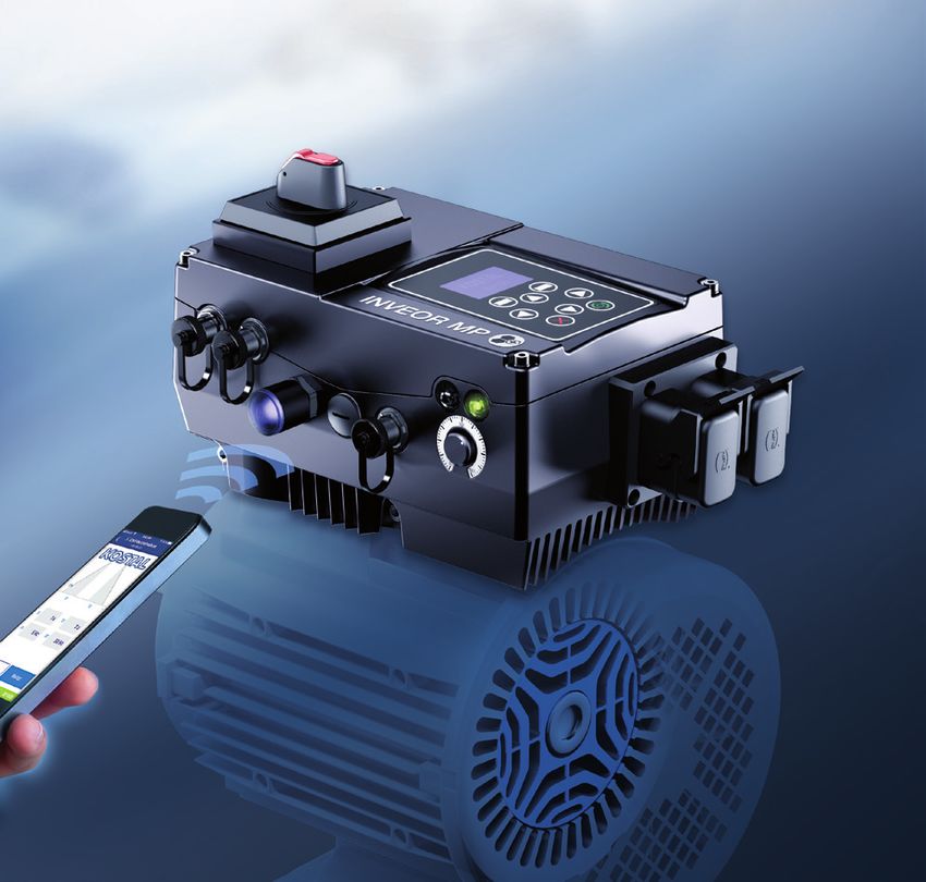
Data sheet INVEOR MP Modular
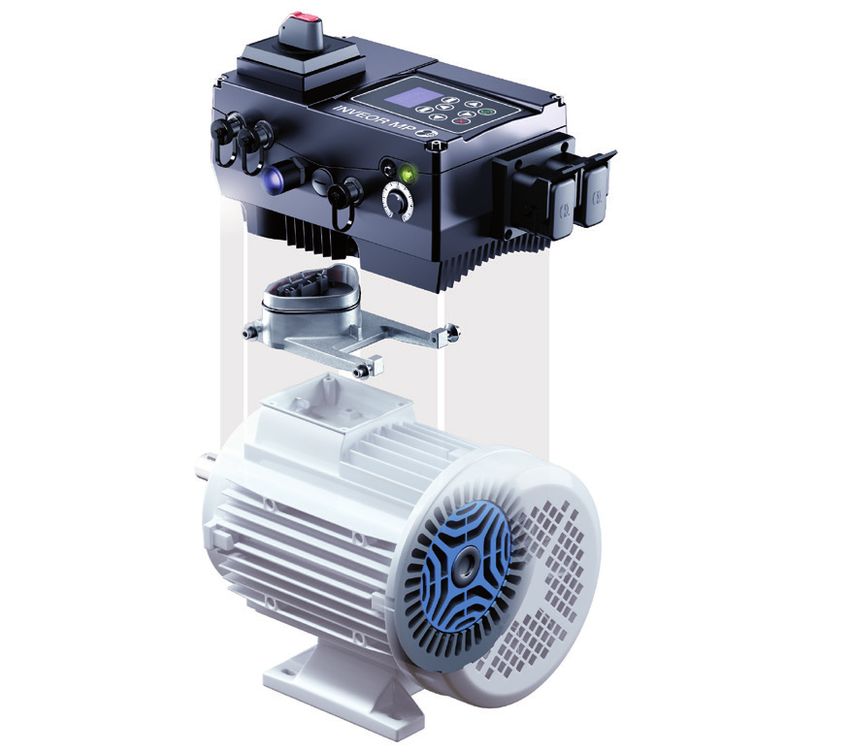
INVEOR – "Smart connections." on five levels

     1         The INVEOR                                                                       3    Operation and observation

IP65 protection class                                                                           Potentiometer

Design without a fan                                                                            M12 RS485 service interface
up to 11 kW
                                                                                                Main switch
Cover level and internal space
for e.g. the customer to                                                                        MMI handheld controller
mount a switch
                                                                                                MMI cover option
100% of connections can be
plugged in (Harting plug                                                                        Touch operating terminal
HAN Q4/2, Quickon)
                                                                                                PC software: KOSTAL INVERTERpc
Optional slots                                                                                  www.kostal-industrie-elektrik.com/
                                                                                                KOSTAL INVERTERpc
Brake module
                                                                                                App: KOSTAL INVERTERapp
Robust and vibration-resistant
housing concept

Internal PTC brake resistor

Functional safety 1)                                                                            4    Motor adaptations

                                                                                                Robust and vibration-resistant adapter
                                                                                                concept

                                                                                                Motor adapter concept compatible with
 2         Communication                                                                        all commercially available motors

                                                                                                Mechanics of motor adapter compatible
                                                                                                with INVEOR M product group

                                                                                                5    Control process

                                                                                                Supports all synchronous reluctance,
                                                                                                synchronous and asynchronous motors
                                                                                                with maximum energy efficiency

                                  PMSM                   IPMSM                 Synchronous
     Asynchronous motor
                            (magnets on outside)    (magnets on inside)      reluctance motor

                      1)

                                ENERGY-EFFICIENT        IE5 SUPPORT
1)
     In 2020                    DRIVE CONTROLLERS       SYNCHRONOUS MOTORS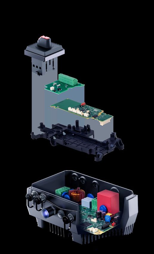
400 V devices, technical data for INVEOR MP Modular
Size
A B C 7) D 8)
Recommended motor rating1) [kW]
0.55 0.75 1.1 1.5 2.2 LD 5) 2.2 3 4 5.5 LD 5) 5,5 7.5 11 LD 5) 11 15 18.5 22 30 LD 5)
Supply voltage 3 x 200 V AC -10 %...480 V AC +10 %
280 V DC -10 %...680 V DC +10 % 2)
Grid frequency
50/60 Hz ± 6%
Network configurations
TN / TT
Line current [A]
1.4 1.9 2.6 3.3 3.9 4.6 6.2 7.9 9.3 10.8 13.8 18.3 23.2 28.2 33.2 38.2 49.8
Rated current output eff. [IN at 8 kHz]
1.7 2.3 3.1 4 4.8 5.6 7.5 9.5 11 13 16.5 22 28 34 40 46 60
Electrical data
Min. brake resistance [Ω]
100 50 30
Overload for 60 sec. [%]
150 110 150 110 150 110 150 110
Overload for 3 sec. [%]
200 150 200 150 200 150 200 150
Switching frequency
Auto regardless of temperature, 2 kHz, 4 kHz, 6 kHz, 8 kHz, 12 kHz, 16 kHz (factory setting 4 kHz)
Output frequency
0 Hz – 599 Hz
Mains cycles of operation / restart
Unlimited 3) > 2 min.
DIN EN 61800-5 touch current
< 3,5 mA 4)
Protective function
Functions
Overvoltage and undervoltage, I2t restriction, short-circuit, ground leak, motor and drive controller temperature, stall prevention, blocking detection
Software functions
Torque control 6), multiple pumps, fixed frequencies, data record changeover, flying restart, motor current limit
Housing
Two-part aluminium die-cast casing
Dimensions [L x W x H] mm
Mechanical data
233 x 153 x 120 270 x 189 x 140 307 x 223 x 181 414 x 294 x 232
Weight including adapter plate [kg]
3.9 5.0 8.7 21.0
Protection class [IPxy]
IP 65 IP 55
Cooling
Passive Cooling Active Cooling
Climate class (DIN EN 60721-3-3)
3K3 (50°C) 3K3 (40°C) 3K3 (50°C) 3K3 (40°C) 3K3 (50°C) 3K3 (40°C) 3K3 (50°C) 3K3 (40°C)
Ambient temperature -40 °C (non condensing) to +50 °C -40 °C (non condensing) to +50 °C -40 °C to +50 °C -40 °C to +50 °C
up to +40°C up to +40°C to +40°C to +40°C
(without derating) (without derating) > 50 °C (with derating) > 50 °C (with derating)
Environmental conditions
Storage temperature
-40 °C…+85 °C
Altitude of the installation location
Up to 1000 m above sea level / over 1000 m with reduced performance (1 % per 100 m) / above 2000 m see operating manual
Relative air humidity
≤ 96 %, condensation not permitted.
Vibration class (DIN EN 60721-3-3)
3M7 (3g)
EMC (DIN-EN-61800-3)
C2
Certificates and conformity
Technical data for 400 V devices INVEOR MP Modular (subject to technical changes)
1)
Recommended motor rating (4-pole asynchr. motor) is given based on the 400 V AC supply voltage.
2)
In compliance with the overvoltage category.
3)
< 3 s may result in power failure/intermediate circuit undervoltage faults.
4)
With 1LA7 asynchronous motor, motor-mounted.
5)
Low-duty devices with reduced output currents.
6)
Only for synchronous and reluctance motors.
7)
As of Q3 2020.
8)
As of Q4 2020.INVEOR MP Modular – Individually smart.
Main switch
Brake module
MODULES
IO module
In 2020
Module carrier
Power stack, self-contained
POWER STACK
Works without extra controller cards.
M12 IO
M12 MMI
Model Without IO module With IO module 1
I/O interfaces 1) - 3 DI / 1 DO
STO input Sil 2 PLd - Option 2)
Potentiometer on device - Option
MMI/MMI option - Option
Bluetooth - Option
Internal power supply - 24 V DC, 100 mA short-circuit proof
External feed-in 24 V DC - only with STO or fieldbus option
Fieldbus integrated 1) Modbus RTU or CANopen Modbus RTU and CANopen
Fieldbus option - Profinet, Sercos III optional
Brake module - Option
Main switch - Option
Technical data for INVEOR MP Modular 400 V devices (subject to technical changes)
1)
Via M12 plug connector (optional)
2)
In 2020Contact
KOSTAL Industrie Elektrik GmbH
Lange Eck 11
10 / 2019 – D/Iα – EN – 1000
58099 Hagen
Deutschland
Telephone: +49 2331 8040-468
Fax: +49 2331 8040-602
info-industrie@kostal.com
www.kostal-industrie-elektrik.comYou can also read


