Delphi Mk VI Owner's Manual - Oracle Audio Technologies - The Fine Art of Playing Music
←
→
Page content transcription
If your browser does not render page correctly, please read the page content below
The Fine Art of Playing Music

     Oracle Audio Technologies

         Delphi Mk VI
        Owner’s Manual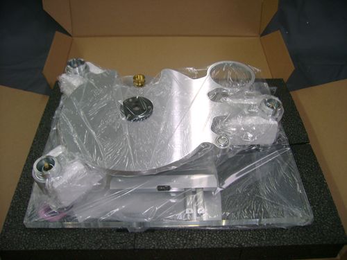
FOREWORD

Thank you for purchasing the Oracle Delphi MK VI. We truly appreciate your support !

This is your Delphi Mk VI owner’s Manual. The following pages will describe as succinctly as possible
the assembly of your new turntable. Although some operations are self explanatory, we strongly
suggest you read this booklet thoroughly to better understand the importance of the different key
adjustments.

Your Delphi Mk VI is a precision instrument and its performance is directly linked to the quality and
accuracy of the different adjustments you will perform. It is important to set up your new turntable with
the utmost care so it can effectively convert record groove modulations into outstanding musical
performance and enjoyment!

Maximum performance and total accuracy of your source system can only be achieved by following a
logical step by step process where each and every minute details about the turntable suspension
calibration, tone arm and cartridge installation and alignment are carefully and accurately addressed
and executed with maximum precision.

                          The Oracle Delphi turntable is an artwork of geometry.
                            Please take your time setting up your turntable !

__________________________________________________________________________

FOR YOUR RECORDS
Oracle Delphi Mk VI, serial Number:

Power Supply Serial Number:

Dealer Name:

Dealer Address:

Dealer Phone:

Purchase Date:

We suggest you keep your sales slip together with this owner’s guide.

                                        Oracle Audio Technologies                                       2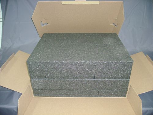
TABLE OF CONTENTS

Unpack your Delphi MK VI .................................................................. 4
Assemble the sub-chassis ................................................................... 6
Install the tone arm and phono cartridge.............................................. 6
Precisely align the phono cartridge ...................................................... 8
Assemble and level the plinth .............................................................. 9
Install the MVSS plungers.................................................................. 10
Prepare and install the suspension modules...................................... 11
Calibrate the suspension ................................................................... 12
Filling the MVSS reservoirs with the Silicone fluid ............................. 13
Install the drive belt ............................................................................ 14
Calibrating the Micro Vibration Stabiliser System .............................. 16
Attach the phono lead ........................................................................ 17
Connect the power supply ................................................................. 17
Adjust the 33 / 45 speed .................................................................... 17
Attach the ground lead....................................................................... 18
Install and calibrate the hinges........................................................... 18
The record clamp and tapered washer .............................................. 19
Level your Delphi MK VI .................................................................... 20
Maintenance ...................................................................................... 21
Specifications..................................................................................... 21
Warranty registration card.................................................................. 22

                                  Oracle Audio Technologies                                              3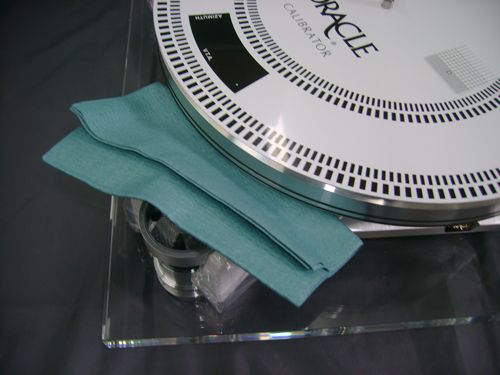
UNPACK YOUR DELPHI MK VI
Before you begin the set up process, it is important that you find a clean and rigid surface where you will be able
to safely place the turntable for the assembly. Make sure there is adequate lighting.
The packaging system has been designed to protect your Oracle from the abusive handling normally
encountered during shipping. Such packing materials are expensive. ( the replacement cost is around $ 250 ).
We recommend you save it and also save the plastic bags for future handling. When repacking your turntable,
position each item in its allocated section. When repacking always use the protective plastic bags to prevent a
direct contact between the clear protective coating and the foam packaging.
It is mandatory to use the original packaging for any warranty return to the factory.
All the accessories are strategically and safely located in the packaging to prevent them from flying loose to
prevent any damage to your turntable during shipping.
The very first step …
• Open the outer box.
• Remove the four protective foam corner pieces.
• Lift the inner box by lifting it straight up and out.
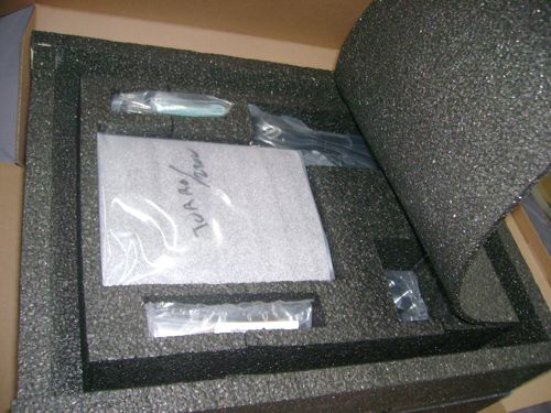
• Open the flaps on both ends and and then the top cover, the inner box will then spread open.
Items located in the TOP section of the foam packaging:
• Dust cover (optional item ordered separately)
• Calibrator disc
• Spindle holder lubricating oil
• Record clamp
• Oracle Power supply
• Drive belt
• Drive belt installation tool
• Lint free cloth
• Suspension adjustment gauge
• Tool bag (screw driver, allen keys, 5/32" 9/64"-3/32"-5/64")
Oracle Audio Technologies 4
Items located in the bottom section of the foam packaging:
       •   Acrylic plinth and drive module assembly
       •   Platter
       •   Brillance cleaner
       •   Hinges ( if ordered with a dust cover or if required )
       •   Strain relief device
       •   Spindle holder assembly
       •   One extra suspension spring, Blue
       •   Three suspension caps
       •   Three reservoirs for the Micro Vibration Stabilizer System ( MVSS )
       •   Three plungers and wheel lock nut for the MVSS

                            Oracle Audio Technologies                            5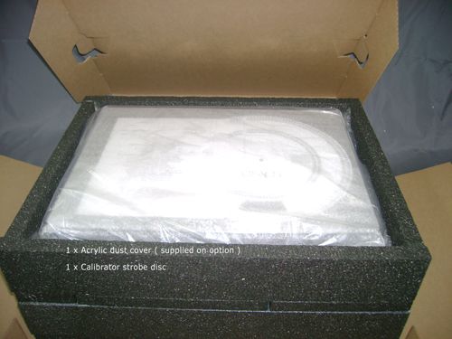
ASSEMBLE THE SUB-CHASSIS

Important note : The platter is located below the acrylic base with the spindle pointing up.
Carefully lift the acrylic base and drive module assembly straight up so as not to damage the platter’s
spindle.

Assembling the spindle holder to the sub-chassis

   •     Locate the spindle holder assembly and remove the 3 mounting screws.
   •     Retrieve the 9/64th“ allen key in the tool kit.
   •     Lift the sub-chassis straight up and install the spindle holder from under the sub-chassis (ground lug
         side).

Note :                DO NOT FILL THE SPINDLE HOLDER WITH OIL AT THIS TIME

INSTALL THE TONE ARM AND PHONO CARTRIDGE
Precaution – When performing anything near the tonearm and cartridge, we recommend not wearing
loose clothing, ties, sweaters or anything than can catch and damage the cartridge cantiliver.

Install the tone arm following the manufacturer’s recommendations.
Notes :
          -   At this time the MVSS plungers and wheel lock nuts will not be fitted to the sub-chassis.
                                           Oracle Audio Technologies                                              6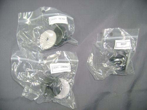
-   The Silicone reservoirs will be installed on the acrylic base later during the assembly process.
     -   The drive belt should not be installed for this operation.
     -   Handle the platter installation carefully to prevent any damage to the precision screws inside the
         spindle holder.
     -   The tonearm installation and calibration will be easier and safer with the sub-chassis resting on the
         foam shipping blocks as shown below.

•   Remove the protective bag from around the sub-chassis, remove the styrofoam support blocks then
    remove the plastic bag from around the acrylic plinth.
•   Remove and set aside the suspension tower modules (i.e. the suspension housing, the spring and all
    related parts).
•   Level the plinth by turning the adjustable feet below the acrylic base. Since this is only a preliminary
    adjustement you can use the 3 foam blocks to establish a parralell plane between the sub-chassis and
    the acrylic base … then use the sub-chassis spirit level as a reference to adjust the feet. This operation
    is preferable to ensure that you obtain accurate readings when you do the different adjustements that
    will follow. A final levelling of the adjustable feet will be necessary when you position your Oracle Delphi
    MK VI in its final environment.
•   Carefully guide the platter’s spindle vertically in its holder.
•   Place the tone arm mounting board loosely in the sub-chassis mounting ring and determine the correct
    distance and direction to mount the arm to the arm board.
•   First mount the tone arm to the pre-cut aluminum board.
•   Properly secure the tone arm mounting hardware.

                                      Oracle Audio Technologies                                                7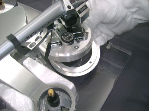
Important safety precaution ! If you are planning to cut your own mounting board, remember
that the cutting of the arm board can sometimes be troublesome as well as being a potential hazard.

It is extremely important to precisely drill the tone arm board as recommended by the manufacturer with
the proper center to center specification to make sure the tone arm can perform to its full potential.
The use of an adequate tooling is important to both accuracy and safety.

    •   Use stainless steel or aluminium screws to mount the cartridge for maximum rigidity.
    •   In preparation for the final alignment, tighten the phono cartridge screws very lightly so it can be moved
        in the headshell.

PRECISELY ALIGN THE PHONE CARTRIDGE
The Calibrator disc is a precision protractor and strobe disc. It is an important tool to achieve an accurate
calibration of the tone arm and phono cartridge geometry.

Important ! Do not use tape on any of the aluminum parts. Doing so could make the paint peel off ! This notice
applies to all aluminum parts, the sub-chassis, the platter or other aluminum parts.

Important ! Before you proceed to the cartridge alignment on the Calibrator disc grid make sure the platter is
kept from moving by inserting the blue cloth between the platter and the sub-chassis. Any movement of the
platter with the stylus cued down on the Calibrator disc could result in irrevocable damage to the stylus or the
cantilever.

    •   Place the Oracle Calibrator disc on the platter over the acrylic mat.
    •   Block the platter using the blue cloth by skeezing it between the platter and sub-chassis.
    •   Aim the black alignment line (Located over the “O” of Oracle) with the pivot center of the tone arm.
    •   Adjust the stylus pressure to approximately 1.5 gram.
    •   Move the tone arm over the alignment grid and cue it down.
    •   Check for the horizontality of the arm tube with the surface of the calibrator disc or use the tone arm
        manufacturer's supplied tool, adjust the height accordingly. ( This will influence the vertical tracking
        angle … VTA )
    •   Bring the tone arm over the center of the grid again and lower it. The ultimate goal is to make the stylus
        tip fall exactly in the pin hole in the center of the grid. If not, position the cartridge so it does. This can be
        done by either moving the phono cartridge in the headshell or in the case of a Oracle SME tone arm,
        moving the base of the arm back or forth so it does. ( read the tone arm instructions )
    •   Precisely align the body of the cartridge with the lines of the grid. A more accurate way is to visualize the
        cantilever as an extension of the center line of the grid. ( This is the Zenith angle alignment )
    •   Secure the cartridge screws and repeat the previous operation.
    •   Check the azimuth ( lateral view of the cantilever ) by lowering the stylus over the black portion on the
        calibrator disc. The mirror reflection will help determine if the cartridge is off its vertical axis.

                                            Oracle Audio Technologies                                                   8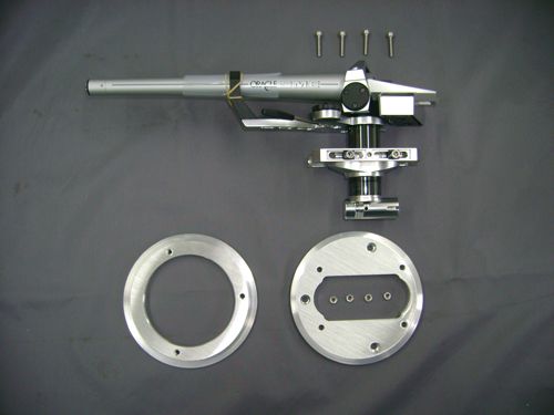
Note : We have been using with great success the Adjust Plus computer program and test record system
designed by Dr. Chris Feickert in Germany. We can assure you that this is a very efficient and accurate system
to obtain the best possible Azimuth alignment for your phono cartridge. We can also testify that this calibration
can not be achieved by simply eyeballing the stylus ! The optimal Azimuth calibration will allow to best possible
Right and Left channel separation. The system also allows to reach the optimal phase coherency between Right
and Left channel. Other tools are available for an optimal Azimuth calibration.

    •   Check the stylus pressure using an accurate gauge and adjust it to the cartridge manufacturer's
        specifications.
    •   Install the stylus guard to complete the assembly of your Delphi Mk VI. Do not install the phono lead at
        this time. If there is no stylus guard for your phono cartridge use a tie wrap to secure the tone arm tube
        in the arm rest support.

You are now ready to complete the assembly of your Oracle Delphi MK VI …

    • Remove the platter from the spindle holder and set it aside
    • Secure the arm tube of the tone arm in the arm rest with a tie-wrap to prevent it from swinging out while
      handling the sub-chassis
    • Gently lift the sub-chassis / tone arm / cartridge assembly and set it aside to be able to complete the
      assembly of the turntable plinth. Use the white foam blocks to safely support it.

ASSEMBLE AND LEVEL THE PLYNTH ASSEMBLY
    •   Retrieve the 3 Silicone reservoirs and mounting screws from the bottom section of the foam packaging.
    •   Mount the Silicone reservoirs on the acrylic base as shown on the picture.
    •   Secure the screw lightly using the 3/16th allen key.

                                          Oracle Audio Technologies                                                  9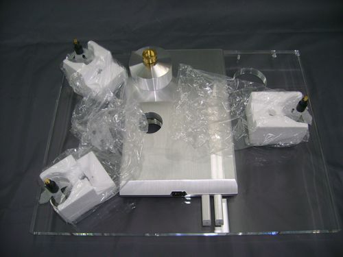
Note:       DO NOT FILL THE RESERVOIRS WITH THE SILICONE FLUID AT THIS TIME. THIS OPERATION
            WILL BE CARRIED OUT AFTER THE SUSPENSION TUNING.

INSTALLING THE MVSS PLUNGERS
Before you proceed to the mounting of the Micro Vibration Stabilizer System ( MVSS ) make sure to positively
identify where each of them need to be installed. The small plastic bags are identified Front left, Rear left and
Right side. The 3 plungers and 3 wheel lock nuts have been pre-mounted to your sub-chassis at the factory to
allow the drilling of the locator mark ( the indentation with the white spot ). This is why they are marked to be
installed at a specific location on the sub-chassis.

    •   Install the plungers and wheel lock nuts on the threaded stems below the sub-chassis making sure the
        raised shoulder of the wheel lock nut is installed towards the sub-chassis.
    •   Install each threaded plunger at the position indicated on the plastic bag and thread both the wheel lock
        nut and the plunger all the way up loosely against the sub-chassis.

                                          Oracle Audio Technologies                                             10
PREPARE AND INSTALL THE SUSPENSION MODULES
Note : The calibration of the springs in the suspension system is accomplished by moving the spring up or
down inside the threaded plastic holder. The springs are color coded as follow from the weakest to the
strongest, Yellow, Red, Green and Blue. The color coding is visible from the inside at the wider end of the
spring. In this document, the reference to clockwise or counter-clockwise is determined by viewing the spring
from above the turntable unless stipulated otherwise.
When holding the smaller end of the spring it can easily be rotated counterclockwise in its holder. To rotate the
spring clockwise, grab the wider end of the spring below the threaded holder. If there is not enough coils coming
out below the plastic sleeve you can use needle nose pliers and insert the tip between two coils below the
sleeve. It is then possible to rotate the spring clockwise. If no coils are visible from below the sleeve, simply
thread the spring completely out through the sleeve from above then re-insert it from below and thread it up in
the sleeve until 2 or 3 coils are left out below the spring sleeve.
Explanation … The reason for this is quite simple, a counterclockwise rotation of the spring forces the coils
to become smaller beause you are in fact rotating it in the direction of its windings. Trying to rotate the spring
clockwise will work against the windings and this will make the spring become bigger thus making it more
difficult or possibly impossible to move freely in its holder.
The standard factory spring combination will accommodate most tone arms.
The factory setting is as follow :
- Yellow spring …Front left tower
- Red spring … Rear left tower
- Gren spring … Right side tower
Step one – Initial setting of the spring.
• Thread the spring in the plastic spring holder so three coils are showing below the holder.
Step two – Meticulously assemble the suspension spring modules.
• Position the upper spring damper and nylon sleeve over the Delrin suspension stem.
• Install the Sorbothane damper over the spring holder and seat it well around the lip.
• Insert the spring assembly and seat it well inside the suspension housing.
• Install the suspension housing over the spring assembly.
Note : When inserting the spring assembly inside the suspension housing the stickyness of the Sorbothane
damper could have a tendency to prevent it from properly and fully seating inside the suspension housing.
Running the Sorbothane on a paper towel will make fibers adhere to its surface making it easier to slide in the
suspension housing.
Oracle Audio Technologies 11CALIBRATE THE SUSPENSION
Note: For a more accurate tuning of the suspension system of your Oracle MK VI we recommend that you
install an old record and the record clamp on the platter, this will give a more accurate static load on the sub-
chassis.
- Do not install the drive belt or the phono lead.
- Start the calibration with the Right side suspension module, near the tone arm, then
move to the Rear Left and finally to the Front Left suspension module.
- Do no install the suspension caps at this time
• Position the sub-chassis over the suspension tower modules.
• Install the platter in the spindle holder … without the drive belt.
• Locate the suspension gauge in the tool bag. Note : Do not take into
consideration the section "A", 1 or 2 as they were designed for earlier
models of Oracle turntables.
• Place the gauge on the acrylic base with the "B" side against the lock feet.
Note : If the lower section of the suspension housing is sitting lower than the “B” step on the suspension
gauge, this is an indication that the spring calibration is too soft. Make the spring stronger by grabbing the large
end of the spring below the spring holder and turn clockwise ( remember … as seen from above ). This can be
done by lifting the suspension housing so you can grab the spring with your fingers. If the spring coming out at
the bottom of the spring holder is too short to hold with your fingers use needle nose pliers and hold the spring
by inserting the tip between two coils.
• Make a first round of calibration of the suspension system so all three suspension housings are set at
about 3 mm (0,125 inch) above the "B" step. To do so hold the spring from above the suspension
housing and rotate counterclockwise by small increments. This will result in making the spring softer
thus allowing the suspension housing to sit lower.
Note : After you’ve changed the setting of a spring always apply a slight downward pressure then lift the
suspension housing slightly to unload the twisting stress. This will achieve a more exact reading of the
adjustement just performed.
• Make a final round of calibration of the suspension system so all three suspension housings are set at
about .5 mm (0,020 inch) above the "B" step.
• Over a period of a few days the springs suspension system will set to the desired optimal setting.
Oracle Audio Technologies 12Note : Once the final adjustment is completed it is important to validate that part of the the spring is visible
below the plastic spring holder in each tower. This can be done by simply lifting the suspension housing just
enough so you can see the spring coils below the sleeve. If you can see the spring anywhere from almost flush
to up to 4 coils out of the spring holder, the calibration is in a safe range. More than 4 coils visible would indicate
that you are using a spring which is too soft for the location it has been installed. If “NO” part of the spring is
visible below the spring holder this is an indication that the spring in that tower is too strong, we recommend the
use of a softer spring.
Explanation … As an exemple, if you would use a green spring in the front left suspension tower this spring
would be much too strong for this position … in attempting to make the spring softer to reach the “B” step on the
suspension gauge you would have to thread the spring way up in its threaded holder … most probably to the
point where it would physically pop out from the top of the holder ! Using such a strong spring at a wrong
position and threading it too far up in the spring holder could eventually cause the spring to snap out of the
threaded holder thus potentially causing the whole chassis to collapse which could cause damage to your record
and / or your phono cartridge! … Beware !
FILLING THE MVSS RESERVOIRS WITH THE SILICONE FLUID
Note : At this time in the set up process of your Oracle Delphi MK VI the drive belt is not installed, there is no
oil yet in the spindle holder and the phono lead is not yet attached to the base of the tone arm. The suspension
system has been precisely calibrated … it is now time to fill the reservoirs with the Silicone damping fluid.
• Remove the platter and the sub-chassis and set them safely aside. Handle the sub-chassis with extreme
care to prevent any damage to the phono cartridge. Make sure the a tie wrap is safely holding the arm
tube in the arm rest and the stylus guard is installe …if available.
• Retrieve the Silicone damping fluid syringe and fill each reservoir so the Silicone reaches the center
line inside the reservoirs. You will obtain the best result by doing this operation in 2 or 3 steps. It is
important not to overfill the reservoirs
• Install the sub-chassis back over the suspension towers.
Oracle Audio Technologies 13• Retrieve the oil syringe and depth gauge from the packaging.
• Fill the spindle holder with the oil supplied with your Oracle MK VI and use the depth gauge to make
sure the exact amount of oil is used in the spindle holder. The optimal quantity of oil to be added in the
spindle holder is 3cc.
INSTALL THE DRIVE BELT
Drive belt installation tool …
Note : To reduce any contamination problem wash your hands prior to handling the drive belt
• Retrieve the drive belt and the installation tool from the upper section of the foam packaging.
• Place the platter on your lap with the spindle pointing up.
• Position the drive belt around the inner hub of the platter.
• Take the drive belt installation tool and and insert the two ends to catch the drive belt.
• Pull the tool away from you and flip it around the edge of the platter
• Run your finger around the inner hub of the platter so it is between the drive belt and the hub and move
the drive belt near the upper edge so it rests at about 3mm ( 1/8 inch ) from the upper edge of the inner
hub.
Explanation … If the drive belt remains at the bottom of the platter around the inner hub there will be a
misalignment with the height of the motor pulley. When the platter starts rotating the drive belt will then jump out
of the motor pulley.
• Bring the platter over the spindle holder, align the drive belt installation tool so the motor pulley falls
between the two legs of the tool.
• Carefully lower the platter straight down in the spindle holder.
Oracle Audio Technologies 14Important notice : Extreme care must be taken to keep a vertical alignment of the spindle with the spindle
holder to prevent any damage to this precision screws inside the spindle holder.
• Rotate the platter by hand just so the installation tool is out of the axis on the motor and the drive belt
starts engaging in the motor pulley.
• Flip the drive belt installation tool towards the center of the platter as indicated in the picture below.
Note : Remember that each time the platter is removed from the spindle holder a certain quantity of oil will be
lost … the oil syringe we supply contains 4cc of oil. The special mix of Synthetic / PTFE lubricating oil supplied
with your Delphi Mk VI is designed to protect and preserve the mating parts for many years. Unless
contaminated
with dirt or alcohol, this lubricating oil will last for many years. In the event that the drive belt becomes
contaminated, clean it with Isopropyl alcohol. Clean the motor pulley and the drive hub at the same time.
Oracle Audio Technologies 15CALIBRATING THE MICRO VIBRATION STABILIZER SYSTEM
• Calibrate all three plungers 2½ turns down by turning the plungers clockwise ( looking from above ).
• Lock the plunger in position using the wheel lock nut.
Note : Once the reservoirs have been filled and the plungers have been in contact with the Silicone we
suggest the following procedure … If you have to remove the sub-chassis from the suspension towers unscrew
the plunger completely ( by turning it clockwise as viewed from above ) until it falls in the Silicone reservoir.
Leave the wheel lock nut on the sub-chassis. This way there will be no loss or spillage of the Silicone when you
lift the sub-chassis off the suspension towers. When you re-install the sub-chassis just thread the plungers back
on their threaded stems and proceed to the suspension calibration on page 12.
Explanation … The whole concept and operational logic of the suspension and the MVSS is based on the
fact that both, the level of the Silicone fluid inside the reservoirs and the calibration of the suspension tower
using the suspension gauge has been executed with maximum accuracy. The purpose of the MVSS is to
capture and dissipate micro vibrations present within the floating sub-chassis without short circuiting the
efficiency of the suspension system. By eliminating micro vibrations, the tone arm / cantilever / stylus / platter
interaction becomes more accurate, the whole combination becomes more stable and better controlled. This
increased stability allows the phono cartridge stylus to retrieve more accurate information from the record groove
which translates into a more accurate signal reproduction and impacts the whole frequency range. This global
sonic improvement is very noticeable at all levels… musical accuracy, harmonic balance and integrity, transient
response, dynamic contrast, tonal balance, depth of image … etc.
Finally, you the listener suddenly becomes more musically involved !
What the MVSS consist of …
Beside each suspension tower a small reservoir is filled up to its inner center line with an extremely low viscosity
Silicone fluid. The reservoirs are secured to the acrylic base. A threaded stem is mounted to the sub-chassis
lining up with the Silicone reservoirs. The threaded wheel lock nuts and the adjustable taper shaped plungers
are threaded on the sub-chassis threaded stems to complete the mechanism. Once the tone arm and cartridge
are precisely calibrated and the suspension system perfectly adjusted the turntable is ready to operate.
How the MVSS control works …
When in the full “UP” position ( completely against the sub-chassis ) the plungers barely come in contact with the
Silicone fluid in the reservoirs. If you play your Oracle without the MVSS plungers inserted in the Silicone
reservoirs there will be no or very limited on the control of micro vibrations. Each full turn of the plunger will
result in a 1,27mm ( 0,050” ) vertical displacement. A similar calibration will be repeated for each plunger. Since
we are dealing with micro vibrations it is extremely important to lock the plunger in position with the wheel
lock nut. Leaving the plungers in an unlocked position will defeat most of the purpose of the MVSS. At the
factory the best results were achieved with a calibration between 2 and 3 ¼ turns down. This represents a
plunger penetration from 2,54mm (0,100”) to 4,127mm (0,162”) into the Silicone fluid reservoirs. In fact, it is a
little more than this because the surface of the plunger that is immerged in the Silicone forces the fluid up in the
reservoirs. The MVSS fine tuning is guided by two factors, the room ambient temperature and your personal
musical preferences. The MVSS has been designed so it can overdamp micro vibrations … it is extremely
important to understand this reality ! If the plungers are calibrated too far down ( 4 turns down for exemple ) in
the Silicone reservoirs some mechanical energy will start bypassing the suspension system. The system has
been purposely designed like this to make sure the optimal calibration of the MVSS could be achieved under all
conditions.
Oracle Audio Technologies 16ATTACH THE PHONO LEAD ( Does not apply with the granite base option )
• Plug the phono lead to the base of your tone arm.
• Retrieve the strain relief device from the packaging.
• Secure the lead to the strain relief device form above or below the plinth.
• Create a loop from the base of the tone arm to the strain relief device to prevent any interference of the
lead with the suspension system. Make sure the looped wire does not come in contact with the table
below.
Note : In some applications, the phono lead might be too stiff. It is recommended to split the moulded wire
from the plug to the strain relief. If the loop is too long, the lead could come in contact with the table below. If it
is too short, it will prevent the suspension system from moving freely. In both cases, this would be detrimental to
the sound.
CONNECT THE POWER SUPPLY
• Plug the power supply output to the turntable input receptacle located to the rear of the turntable.
• Plug the input cord to an AC outlet.
Note : Keep the power supply away from signal carrying leads. The power supply can remain connected to the
wall outlet unless you don’t intend to use the turntable for a long period of time.
ADJUST THE 33 AND 45 SPEED
Oracle Audio Technologies 17Note : The 33 speed must always be calibrated first. The individual speed potentiometers are accessible
from the rear of the drive module. When viewing the module from the rear, a clockwise rotation of the
potentiometer will result in an increase of the selected speed. The inner circles of strobe marks on the calibrator
disc are to be used at 50 Hz. The set of strobe marks closer to the center are for the 33 RPM, the one next to it
is for the 45 RPM. The outer strobe marks are to be used at 60 Hz. The outermost circle is for 45 RPM, the one
next to it is for 33 RPM. The use of incandescent or fluorescent lighting is required to accurately read the
calibrator disc. When the right speed has been reached the appropriate set of strobe marks will be standing still,
with no back or forth movement.
• Place the calibrator disc over the spindle, on the platter.
• Select the 33 speed and check for accuracy.
• Insert the small screw driver supplied with the tool kit in the 33 hole at the rear of the drive module.
• Rotate the 33 speed potentiometer, located to the left, when viewing the module from the rear, until the
strobe marks on the calibrator disc come to a standstill position. Rotate clockwise to increase the speed
and counterclockwise to reduce the speed.
• Select the 45 speed and check for accuracy.
• Insert the screw driver in the 45 hole and repeat the above procedure.
ATTACH THE GROUND LEAD
• Loosen the thumb nut from under the sub-chassis near the tonearm and insert one end of the groung
lead.
• Attach the other end of the lead to the ground post of your pre-amplifier.
INSTALL AND CALIBRATE THE HINGES
( Supplied when purchasing the optional dust cover )
• Locate the hinges in the lower section of the packaging and the appropriate allen key (3/32") from the
tool kit.
• Mount the hinges to the plinth and do not tighten the screws completely. Make sure the dust cover slots
line up correctly with each other before securing the screws.
• Install the dust cover by sliding it in the hinge slot.
Oracle Audio Technologies 18• To make the front of the dust cover rest higher in the low position, rotate the vertical set screw
counterclockwise.
• To increase the spring tension to hold the dust cover in the open position rotate the rear set screw
clockwise.
Note : If the dustcover can not be lifted fully open in its playing area, it is possible to vary the spring tension
of the hinges. The tension has been pre-calibrated on both hinges at the factory to its best performance. The set
screw located vertically in the hinge base is used to limit the closing of the cover. This will allow the adjustement
of the parallel plane of the dust cover. The set screw located at the rear of the hinge will increase or decrease
the spring tension holding the dust cover in the open position. The springs are not designed to hold the dust
cover open in the mid open position.
THE RECORD CLAMP AND TAPERED WASHER
• Position the tapered washer over the spindle on the acrylic mat
• Place a record over the acylic mat.
• Retrieve the record clamp from the foam packaging
• Tighten the clamp so the record is pushed flat against the mat.
Oracle Audio Technologies 19Note : The tapered washer has been designed to help flatten warped records. It is not recommended to use it
with thicker vinyl records because they have less flexibitity. Furthermore the tapered washer in not needed if the
record in not warped. When using the tapered washer do not over tighten the record clamp because this could
damage your albums by cracking the center hole. A good way to evaluate the proper tension of the clamp is to
use the tip of a pencil and tap the inner groove of the record while tightening the clamp. The taping sound will be
hollow at the beginning and will gradually become more solid. This indicates that the record clamp tension is
correct.
LEVEL YOUR DELPHI MK VI
Your turntable is now ready to be moved to its final location.
• Level the acrylic base by turning the levelling feet. Use the sub-chassis spirit level to complete this final
adjustment since the proper, relative level has already been established between the sub-chassis and
the acrylic base in a previous operation.
• Retreive the suspension caps from the packaging and thread them on the suspension stems to
complete your assembly of your Oracle Delphi mK VI
Important note : Whenever you have to either carry your turntable or remove the platter, always remove the
suspension caps to prevent any metal to metal contact between the sub-chassis and the caps which would
damage to the clear protective coating on the aluminum parts of your Delphi MK VI.
Oracle Audio Technologies 20MAINTENANCE
• The blue cloth supplied with your Delphi MK VI can be used to clean all aluminum and acrylic parts
including the mat. Always use the cloth dampened with Brilance to dust the acrylic parts. Do not use
this cloth to pick up oil spills, keep it for the delicate work.
• Unless contaminated, there will be no need to dismantle the spindle holder. If required it is simple to
disassemble it from the sub-chassis. Keep the spindle holder assembly vertical since it contains oil. If
the oil is contaminated it must be disposed of ecologically. Clean the thrust pad and the inside of the
spindle holder with Isopropyl alcohol using a cotton swab. Allow a few minutes for the parts to dry.
Reassemble, making sure to firmly secure the screws. Pour the new oil in the spindle (about 3 cc)
before reinstalling the platter. Use the depth gauge to make sure the right quantity of oil has been used.
• As a precaution to preserve the furniture your Delphi Mk VI sits on, it is advisable to use a folded paper
towel under the spindle holder for a few weeks in the case of an oil spillage.
• The drive belt should be replaced every 3 years for optimal performance.
Additional maintenance notes :
_________________________________________________________________________________________
_________________________________________________________________________________________
_________________________________________________________________________________________
_________________________________________________________________________________________
SPECIFICATIONS
• Powe requirements : 100 / 120 / 230 volts 50 / 60 Hz
• Dimensions : 475mm x 363 mm x 150 mm ( 19 x 14.5 x 6 inches )
• Total weight, acrylic base : 18 Kg ( 39 pounds )
• Total weight, granit base : 30 Kg ( 66 pounds )
• Regular power supply : 24 to 28 VDC / 500ma
• Turbo power supply : T24 to 28 VDC / 500ma … 210 x 184 x 70 mm ( 8,25 x 7,25 x 2,75 inches )
Oracle Audio Technologies 21We are confident your new Oracle product will give you
many years of satisfaction
You are now ready for the real and only purpose of all this...
to sit down, relax and enjoy the Fine Art of Playing Music
From all of us at Oracle Audio Technologies Inc … Thank you !
6136 Boulevard Bertrand Fabi, Suite 101
Sherbrooke, Quebec, Canada
J1N 2P3
Phone: 1-819-864-0480 FAX: 1-819-864-9641
e-mail: info@oracle-audio.com
www.oracle-audio.com
Please fill the section below and mail it back to the above mailing address
to register your new Oracle Audio product.
You can also scan this whole page and send it by e-mail to info@oracle-audio.com
WARRANTY REGISTRATION CARD
Your new Oracle Delphi MK VI carries a non-transferable, 3 year parts and labor limited
warranty against manufacturing defects. Oracle Audio Technologies will repair the defective
item within this warranty period. The original bill of sale from an authorized dealer or
distributor is required for any warranty repair.
Fill the information below and mail a copy back to Oracle Audio for your warranty registration
Oracle Delphi Mk VI serial Number:
Power Supply Serial Number:
Dealers Name:
Dealers Address:
Dealer Phone:
Your Name:
Your Address:
Dealer Phone: e-mail address :
Purchase Date:
Oracle Audio Technologies 22You can also read