Design and Analysis of a Robotic Lizard using Five-Bar Mechanisms
←
→
Page content transcription
If your browser does not render page correctly, please read the page content below
Design and Analysis of a Robotic Lizard using Five-Bar
                                                             Mechanisms?

                                         Rajashekhar V S1 , Dinakar Raj C K2 , Vishwesh S2 , Selva Perumal E2 and Nirmal Kumar
                                                                                   M2
                                              1 Researcher, Tentacles Robotic Foundation, Kanchipuram, Tamil Nadu, India, 603202
                                         2   Department of Mechanical Engineering, Adhiparasakthi Engineering College, Melmaruvathur,
arXiv:2107.12614v1 [cs.RO] 27 Jul 2021

                                                                    Kanchipuram, Tamil Nadu, India, 603319
                                                                           vsrajashekhar@gmail.com

                                                 Abstract. Legged robots are being used to explore rough terrains as they are capable
                                                 of traversing gaps and obstacles. In this paper, a new mechanism is designed to
                                                 replicate a robotic lizard using integrated five- bar mechanisms. There are two five bar
                                                 mechanisms from which two more are formed by connecting the links in a particular
                                                 order. The legs are attached to the links of the five bar mechanism such that, when
                                                 the mechanism is actuated, they move the robot forward. Position analysis using
                                                 vector loop approach has been done for the mechanism. A prototype has been built
                                                 and controlled using servo motors to verify the robotic lizard mechanism.

                                                 Keywords: Robotic lizard · Topological design · Position analysis · Five-bar mech-
                                                 anism.

                                         1     Introduction

                                         Mimicking animals for the purpose of solving human centered problems plays an important
                                         role in the field of robotics. Among these four legged creatures are gaining attention in
                                         the past few decades [1]. Among them MEMS based robots are gaining importance [2].
                                         Miniaturized robots can be used for surveillance and locomotion in cramped spaces.
                                             A lizard is a commonly seen reptile whose mechanics have been studied in detail in the
                                         following literature [3]. It was found that the walking and trotting gaits [4] exhibited by
                                         the lizards were similar to that of the mammals. The biomechanics and kinematics of the
                                         sprawling pattern exhibited by the lizards were studied extensively in [5]. The sprawling gait
                                         has be experimentally shown on a dynamic model in [6]. It is observed that the compliant
                                         and flexible trunk of the lizards help in reducing the peak power [7].
                                             The lizard based bio-inspired robots have been made in the past, such as a water running
                                         robot [8], a leg mechanism [9] and a quadrupeds [10,11]. Motion analyis [12], motion planning
                                         [13] and gait planning [14] based on kinematics of the Gecko have been done on robotic
                                         lizards. A seven degrees of freedom robotic Gecko has been developed for the experimental
                                         verification of the kinematic analysis [15].
                                             Although there are works that exist in the literature that try to replicate a real lizard,
                                         they have not been able to mimic them closely. The novelty of this paper lies in the core
                                         mechanism design and it’s abilty to replicate the gaits of a real lizard. The real lizard that
                                         served as a source of inspiration is shown in Figure 1 (a) and the fabricated robotic lizard
                                         ?   Supported by Tentacles Robotic Foundation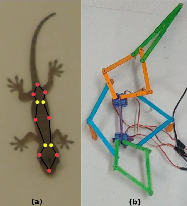
2 Rajashekhar V S et al.
is shown in Figure 1 (b). Topological design has been done using the method mentioned
in [16]. The position analysis has been done using the vector loop approach. Finally the
prototype of the robotic lizard has been shown exhibiting the walking gait.
Fig. 1. (a) The real lizard that served as an inspiration (b) The bio-inspired robotic lizard intro-
duced in this work
2 Topological Design of the Robotic Lizard Mechanism
The design of robotic lizards using mechanisms like Watt-I Planar Linkage Mechanism
[17] and CPG-driven modular robots [18] have been done in the past. In this work, the
development of the robotic lizard mechanism using two active and two passive five-bar
mechanisms is done. The degree of freedom analysis is done to find out the number of
degrees of freedom of the mechanism and also to find out whether the right driving links
have been chosen for the mechanism. This is a eight step process and it is done using the
method given in [16].
Xm X
F= ƒ − ξLj (1)
=1 j=1
j
X
ξLj = dm.((∩=1 Mb ) ∪ Mbj+1 ) (2)
j=1
where,
F - Degree of freedom of parallel manipulator(PM).
ƒ - Degree of freedom of the th joint.
m - Total number of joints in the parallel manipulator.
- Total number of independent loops in the mechanism, where = m − n + 1.
n - Total number of links in the mechanism.
ξLj - Total number of independent equations of the jth loop.
j
∩=1 Mb - Position and orientation characteristic (POC) set generated by the sub-PM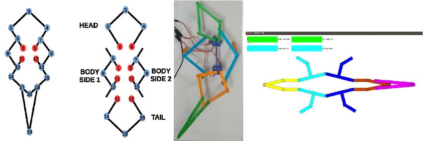
Design and Analysis of a Robotic Lizard using Five-Bar Mechanisms 3
Fig. 2. (a) The topological design of the robotic lizard mechanism. (b) The four five-bar mechanisms
that form the robotic lizard. It is used in position analysis (c) The prototype of the robotic lizard
(d) The graphical user interface developed for the robotic lizard
formed by the former j branches.
Mbj+1 - POC set generated by the end link of j+1 sub-chains.
Calculating the number of independent loops putting n = 13 and m = 16, we get = 4.
The eight steps involved in the calculation of the degrees of freedom of the mechanism is as
follows.
1. The topological structure is mentioned symbolically here.
Branches:
SOC1 (−R1 ||R2 ||R3 −); SOC2 (−R4 ||R5 −); SOC3 (−R1 ||R7 ||R8 −);
SOC4 (−R11 ||R10 −); SOC5 (−R5 ||R7 ||R9 −); SOC6 (−R12 ||R13 −);
SOC7 (−R11 ||R14 ||R16 −); SOC8 (−R12 ||R15 −)
Platforms:
Fixed platform: R1 , R5 , R11 , R12
Moving platform: The rest are all moving platforms
2. An arbitrary point o0 is chosen on the moving platform.
3. Determining the POC set of branches
t 2 (⊥ R )
Mb1 = i=1,2,3
r 1 ||(R )
t 2 (⊥ Rj )
Mb2 = j=4,5
r 1 ||(Rj )
4. Finding the total number of independent displacement equations.
Topological structure of the independent loop
ξL1 = dim(Mb1 ∪ Mb2 )=
t2 t2
dm{ 1 ∪ 1 }
r (||R1 ) r (||R4 )
t2
= dm{ 1 } =3
r (|| (R1 , R4 ))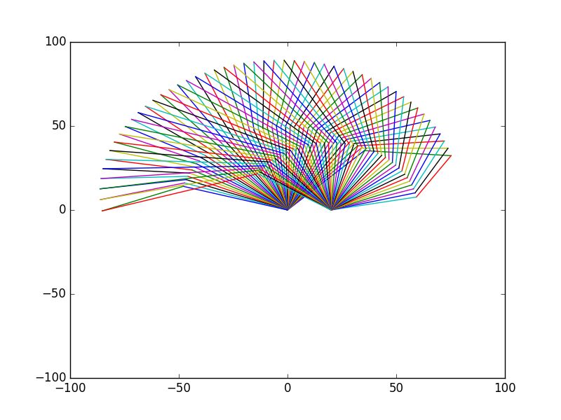
4 Rajashekhar V S et al.
Similarly it can be done for the other 3 loops and the value of the number of independent
displacement equations is found to be the same in each case.
5. Calculating
Pm thePDOF of the mechanism
F = =1 ƒ − j=1 ξLj = 16 − (3 + 3 + 3 + 3) = 4
6. Finding the inactive pairs.
Based on the calculations done in [16], similar steps were followed. It was found that
there is no inactive pair in the mechanism except for the tail which is regarded as passive
linkages.
7. Determining the position and orientation characteristic set of the robotic lizard mecha-
nism.
Based on the formula given in [16],
MP = Mb1 ∩ Mb2
t2 t2 t2 t2
MP = 1 ∩ 1 ∩ ... ∩ 1 = 1
r (||R1 ) r (||R4 ) r (||R12 ) r
The degree of freedom of the mechanism is 4 and the dimension of the above POC set
is 3. Hence the module has two translational and one rotational degree of freedom. The
discrepancy in the values is due to the fact that there is one more rotational degree of
freedom on the same plane which the position and orientation characteristic analysis
has ignored. This is because both the rotational degree of freedom are the same.
8. Select driving pairs
The joints R1 , R5 , R11 and R12 are chosen to be the driving pairs and hence they are
fixed. P
Calculating
Pthe degrees of freedom of the new mechanism,
m
F ∗ = =1 ƒ − j=1 ξLj = 12 − (3 + 3 + 3 + 3) = 0
Since F ∗ = 0, the joints R1 , R5 , R11 and R12 can be used as driving pairs simultane-
ously.
Thus the topological design of the mechanism has been done.
3 Position Analysis of the Robotic Lizard Mechanism
The robotic lizard mechanism is as shown in Figure 2 (c). The vector loop method adopted
from [19] is used for the position analysis of the robotic lizard. There are five vector loop
equations framed, one for the head, two for the body, one for the trunk and one for the
tail. These equations are solved by keeping the known angles on one side and the unknown
angles on the other side. The position of each part of the body is known by substituting the
known four servo motor angles. These equations will be presented in detail in this section.
The vector loop equation of the head which forms a five-bar mechanism in the robotic lizard
is written in Equation 3. It is shown in Figure 2 (b).
R2 + R3 − R4 − R5 − R1 = 0 (3)
Collecting the sin and cos terms together, the Equations 4 and 5 are obtained.
L2 sin(θ2 ) + L3 sin(θ3 ) − L4 sin(θ4 ) − L5 sin(θ5 ) − L1 sin(θ1 ) = 0 (4)
L2 cos(θ2 ) + L3 cos(θ3 ) − L4 cos(θ4 ) − L5 cos(θ5 ) − L1 cos(θ1 ) = 0 (5)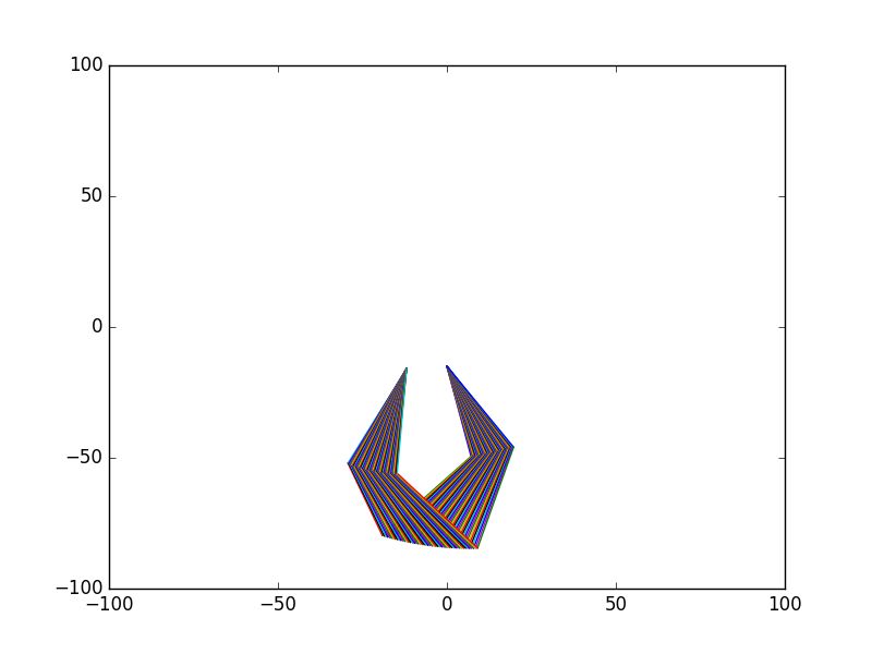
Design and Analysis of a Robotic Lizard using Five-Bar Mechanisms 5
Solving for the θ3 and θ4 by rearranging the Equations 4 and 5, the following are obtained.
p
−B − B2 − 4AC
θ4 = 2 rctn (6)
2A
p
−E + E2 + 4DF
θ3 = 2 rctn (7)
2D
where,
K1 = L5 sin(θ5 ) − L2 sin(θ2 );
K2 = L5 cos(θ5 ) − L2 cos(θ2 ) + L1
K3 = −L5 sin(θ5 ) + L2 sin(θ2 );
K4 = −L5 cos(θ5 ) + L2 cos(θ2 ) + L1
2 2
+K2 2 +K1 2
A = L4 −2 K2 L4−L
2
3
;
B = 2 K1 L4 ;
L4 2 +2 K2 L4 −L3 2 +K2 2 +K1 2
C= 2
L4 2 −L3 2 +2 K4 L3 −K4 2 −K3 2
D= 2
;
E = 2 K3 L3 ;
2 2 2 2
F = L4 −L3 −2 K24 L3 −K4 −K3
Similarly for the rest of the three five bar mechanisms, the vector loop equations are as
follows. For the body side 1, body side 2 and tail,
R6 + R7 − R8 − R9 − R10 = 0 (8)
R12 + R13 − R14 − R15 − R11 = 0 (9)
R17 + R19 − R16 − R18 − R20 = 0 (10)
From the above equations, the values of θ can be found that are similar to Equations 6 and
7. Thus the position analysis has been done for the mechanism.
3.1 Coordiates of Linkages in the Mechanism
The four joints are actuated in a particular order so that the robotic lizard mechanism
exhibits the forward walking gait. The equations governing the coordinates of the linkages
of the head are as follows.
1 = 0
y1 = 0
2 = L2 cos(θ2 )
y2 = L2 sin(θ2 )
3 = 2 + L3 cos(θ2 + θ3 )
(11)
y3 = y2 + L3 sin(θ2 + θ3 )
5 = L5 cos(θ5 )
y5 = L5 sin(θ5 )
4 = 5 + L4 cos(θ5 + θ4 )
y4 = y5 + L4 sin(θ5 + θ4 )
In the similar way, it can be derived for the left and right side of the body, and the tail of
the mechanism.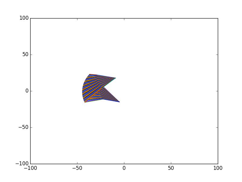
6 Rajashekhar V S et al.
3.2 Workspace of robot parts
The workspace of the robot is plotted by writing a Python Code. The algorithm used for
plotting the workspace of the robot is as follows.
Algorithm 1 Plotting the workspace using position analysis
Declare the range for θ2 and θ5
Declare the length of linkages
For θ5 = 135, θ5 −−, while θ5 < 0
For θ2 = 45, θ2 ++, while θ2 < 160
Calculate Equation 11
plot([1 ,2 ],[1 ,y2 ])
plot([2 ,3 ],[y2 ,y3 ])
plot([3 ,4 ],[y3 ,y4 ])
plot([4 ,5 ],[y4 ,y5 ])
EndFor
EndFor
The Figure 3 (a-d) shows the reachable workspace of the head, tail, body left and body
right of the robotic lizard mechanism.
(a) (b)
(c) (d)
Fig. 3. The workspace of the (a) head (b) tail (c) body left (d) body right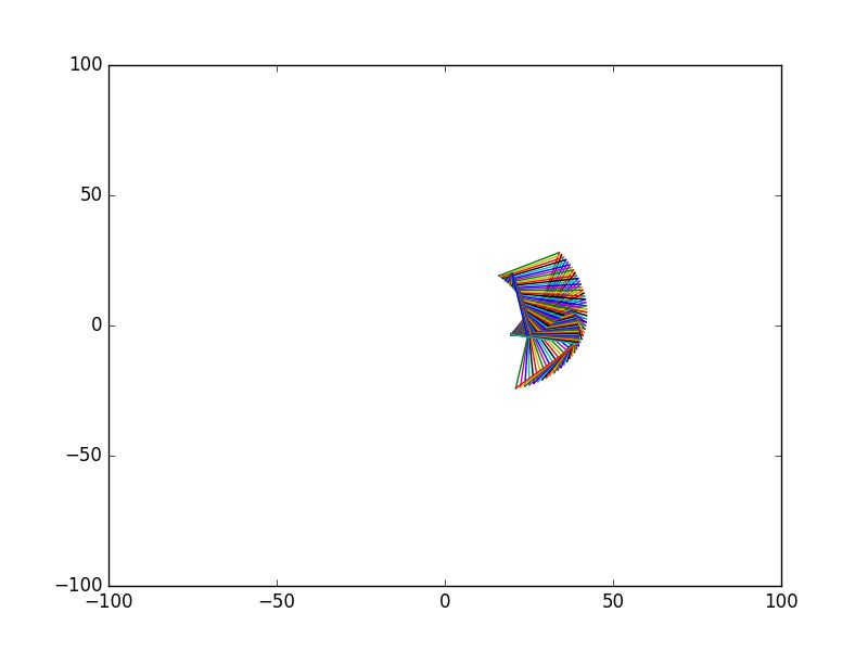
Design and Analysis of a Robotic Lizard using Five-Bar Mechanisms 7
4 Prototype of the Robotic Lizard Mechanism
The links of the mechanism were fabricated using the balsa wood in a CNC router. The
mechanism was actuated using the four servo motors in a particular order. The controlled
used here was Arduino UNO and Processing IDE was used as a graphical user interface
(GUI) to control the robot. The GUI is as shown in Figure 2 (d). The robotic lizard was
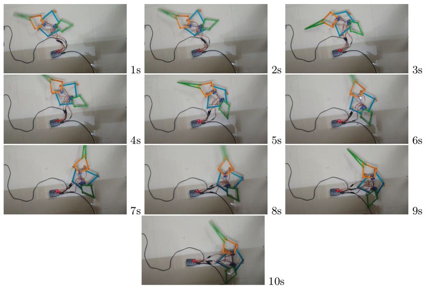
able to move on a flat surface and exhibit the walking gait as shown in Figure 4.
Fig. 4. The robotic lizard exhibiting the walking gait
5 Conclusions
In this work, a new robotic lizard mechanism was developed. The topological design of the
mechanism was done. Then the position analysis of the mechanism was done to find the
various angles between the links. Finally a prototype was made and controlled using servo
motors. A graphical user interface was used to operate the robotic lizard. The future work
would be to implement deep reinforcement learning to obtain a stable gait in unknown
environments.8 Rajashekhar V S et al.
References
1. R. Siegwart, I. R. Nourbakhsh, and D. Scaramuzza, Introduction to autonomous mobile robots.
MIT press, 2011.
2. N. Doshi, K. Jayaram, B. Goldberg, Z. Manchester, R. J. Wood, and S. Kuindersma, “Contact-
implicit optimization of locomotion trajectories for a quadrupedal microrobot,” arXiv preprint
arXiv:1901.09065, 2019.
3. C. T. Farley and T. C. Ko, “Mechanics of locomotion in lizards.,” Journal of Experimental
Biology, vol. 200, no. 16, pp. 2177–2188, 1997.
4. C.-H. Kim, H.-C. Shin, and H.-H. Lee, “Trotting gait analysis of a lizard using motion capture,”
in 2013 13th International Conference on Control, Automation and Systems (ICCAS 2013),
pp. 1247–1251, IEEE, 2013.
5. A. Russell and V. Bels, “Biomechanics and kinematics of limb-based locomotion in lizards:
review, synthesis and prospectus,” Comparative Biochemistry and Physiology Part A: Molecular
& Integrative Physiology, vol. 131, no. 1, pp. 89–112, 2001.
6. C. Kim, H. Shin, and K. Jeong, “Trot gait simulation of four legged robot based on a sprawled
gait,” in 2014 14th International Conference on Control, Automation and Systems (ICCAS
2014), pp. 1031–1036, IEEE, 2014.
7. X. Gu, Z. Guo, Y. Peng, G. Chen, and H. Yu, “Effects of compliant and flexible trunks on
peak-power of a lizard-inspired robot,” in 2015 IEEE International Conference on Robotics
and Biomimetics (ROBIO), pp. 493–498, IEEE, 2015.
8. S. Floyd, T. Keegan, J. Palmisano, and M. Sitti, “A novel water running robot inspired by
basilisk lizards,” in 2006 IEEE/RSJ International Conference on Intelligent Robots and Sys-
tems, pp. 5430–5436, IEEE, 2006.
9. Z. Dai, H. Zhang, and H. Li, “Biomimetics of gecko locomotion: From biology to engineering,”
in 2009 ASME/IFToMM International Conference on Reconfigurable Mechanisms and Robots,
pp. 464–468, IEEE, 2009.
10. H. S. Park, S. Floyd, and M. Sitti, “Dynamic modeling of a basilisk lizard inspired quadruped
robot running on water,” in 2008 IEEE/RSJ International Conference on Intelligent Robots
and Systems, pp. 3101–3107, IEEE, 2008.
11. H. S. Park, S. Floyd, and M. Sitti, “Dynamic modeling and analysis of pitch motion of a basilisk
lizard inspired quadruped robot running on water,” in 2009 IEEE International Conference on
Robotics and Automation, pp. 2655–2660, IEEE, 2009.
12. C.-H. Kim, H.-C. Shin, and T.-w. Jeong, “Motion analysis of lizard locomotion using mo-
tion capture,” in 2012 12th International Conference on Control, Automation and Systems,
pp. 2143–2147, IEEE, 2012.
13. N. Ratliff, M. Zucker, J. A. Bagnell, and S. Srinivasa, “Chomp: Gradient optimization tech-
niques for efficient motion planning,” 2009.
14. D. Son, D. Jeon, W. C. Nam, D. Chang, T. Seo, and J. Kim, “Gait planning based on kinematics
for a quadruped gecko model with redundancy,” Robotics and Autonomous Systems, vol. 58,
no. 5, pp. 648–656, 2010.
15. W. Nam, T. Seo, B. Kim, D. Jeon, K.-J. Cho, and J. Kim, “Kinematic analysis and experimental
verification on the locomotion of gecko,” Journal of Bionic Engineering, vol. 6, no. 3, pp. 246–
254, 2009.
16. T.-L. Yang, A. Liu, H. Shen, L. Hang, Y. Luo, and Q. Jin, Topology design of robot mechanisms.
Springer, 2018.
17. L. Xu, T. Mei, X. Wei, K. Cao, and M. Luo, “A bio-inspired biped water running robot
incorporating the watt-i planar linkage mechanism,” Journal of Bionic Engineering, vol. 10,
no. 4, pp. 415–422, 2013.
18. V. Vonásek, M. Saska, L. Winkler, and L. Přeučil, “High-level motion planning for cpg-driven
modular robots,” Robotics and Autonomous Systems, vol. 68, pp. 116–128, 2015.
19. R. L. Norton et al., Design of machinery: an introduction to the synthesis and analysis of
mechanisms and machines. Boston: McGraw-Hill Higher Education,, 2004.You can also read