DESIGN AND DEVELOPEMENT OF SAFETY GOGGLE
←
→
Page content transcription
If your browser does not render page correctly, please read the page content below

© 2021 JETIR June 2021, Volume 8, Issue 6                                                     www.jetir.org (ISSN-2349-5162)

     DESIGN AND DEVELOPEMENT OF SAFETY
                  GOGGLE
                           Abhishek Raj1, Yash Upadhyay2, Akash Wahiwal3, Prof S.P. Dhamone4
           1
            B.E Student, Department of Mechanical Engineering, SPPU, Pune, P.O. Box 411002, India, abhi22119@gmail.com
     2
         B.E Student, Department of Mechanical Engineering, SPPU, Pune, P.O. Box 411002, India, yashupadhyay300@gmail.com
         3
           B.E Student, Department of Mechanical Engineering, SPPU, Pune, P.O. Box 411002, India, wdakash3113@gmail.com
                   4
                    Associate professor, Department of Mechanical Engineering, SPPU, Pune, P.O. Box 411002, India,
                                                dhamone.sagar@bharatividyapeeth.edu

Abstract: The safety goggles which are cheap doesn't have a good asthetics and cannot be used with the spectacles. The
injection Moulding machine is a machine that melt plasticize the Moulding material inside the heating cylinder and inject this into
the Mould tool to create the molded product by solidifying inside it. Safety goggles are manufactured using injection Moulding.
In previous injection Moulding processes, it required a manual interference to eject the goggles from mould and when the Mould
used to get wear and tear whole Mould was to be changed which are not cheap. In this paper we have tried to design a Mould with
changeable parts which get easily wear and tear and added an ejector which reduces the manual work. We have designed safety
goggles with more uses and has good impact strength. We have used Siemens NX software to design the Mould. We have used
CATIA, HYPERMESH, and Ls Dyana to do analysis of the Safety goggles.

Keywords: Injection Moulding, Plastic, SIEMENS NX- CAD, Safety Goggles, Hypermesh, Catia, Ls Dyana.

                                                      1. INTRODUCTION
Conventional design of Safety goggles has a defect, they are unable to be used with spectacles on. So we are trying in this project
to design a safety goggle with a good impact strength and which can be produced at cheaper costs so that it can be bought by
average customers too. Moulds for safety goggles has a Mould with same material which was a problem in the design, when there
was small wear and tear in the die/ mould whole mould had to be replaced which caused company a great financial loss because
manufacturing a whole new mould requires a lot of machining and a lot of time. The safety goggle mould does not have ejector
pins due to which a manual labour is required to take out the moulded lenses of safety goggles. Injection moulding is one of the
most prevalent technologies used in processing thermoplastic polymers. At the end of the injection moulding cycle, the plastic
moulded part should be ejected when the injection mould opens. So we have tried designing such a mould with such a material
selection that there must be minimum wear and tear. The mould has different parts made of different material which are
replaceable so that whole mould doesn't have to be replaced. And we have used an ejector system in the mould so that manual
labour can be reduced.

                                                   1.1.         PROBLEM STATEMENT

   In these times of pandemic we see a shortages of safety goggles, even if we find it, they can’t be wore on spectacles. The
goggles which are present are very costly. Safety goggles are manufactured using injection moulding process, a manual help is
required to eject the goggles from the mould. And if any small part of mould die gets wear and tear the whole die has to be
replaced. This increases the cost for the company and to manufacture a whole new die consumes a big time.

                                                   1.2.         OBJECTIVES

1.   To design a safety goggle with a good impact strength.
2.   To design safety goggles which are able to be wore on spectacles.
3.   To reduce the cost of labour by using ejector in the moulds.
4.   To reduce the cost of moulds by using different materials for different parts.

JETIR2106329          Journal of Emerging Technologies and Innovative Research (JETIR) www.jetir.org                       c417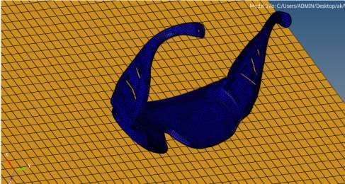
© 2021 JETIR June 2021, Volume 8, Issue 6                                                         www.jetir.org (ISSN-2349-5162)
                                        2. DESIGN & MATERIAL PARAMETERS

1.   Design of model

Figures shows the Cad model of the mould and the safety goggle Figs. 1 (a) shows the Cad image of mould assembly. (b) shows
the safety goggle assembly.

                                                (a)                                    (b)
                                    Figure 1.         (a) CAD Model (b) Drafting of CAD Model

2.   Material properties as per standard

                            Young’s modulus [MPa]           Poisson’s ratio   Density [Ton/mm3]        Tensile strength at break /yield[MPa]
       Material``

                                    2.e^5                                         1.3228e-9
     Poly Carbonate                                              0.31                                                   58

JETIR2106329          Journal of Emerging Technologies and Innovative Research (JETIR) www.jetir.org                                   c418
© 2021 JETIR June 2021, Volume 8, Issue 6                                                                     www.jetir.org (ISSN-2349-5162)
3. Components Used and Dimensions

       PROJECT NAME :-
                                              PLASTIC MATERIAL &            MOULD WEIGTH/ TONN :-
 SAFETY_GOGGLES_CLEAR_LENS -
                                                SHIK :- PC_0.60%              300 KG (Approx)/160T
            BOM
             MOLD BASE & INSERTS SIZES
SR.NO.            DESCRIPTION               FINISH SIZE (IN MM) L X W X H     MATERIAL & GRADE         QTY.              REMARKS / ORDER BY
  1           MAIN CAVITY INSERT                  226.0 X 226.0 X 70.0              STAVAX              1                      (46-48 HRC)
  2            MAIN CORE INSERT                   226.0 X 226.0 X 76.0              STAVAX              1                      (46-48 HRC)
  3               CAVITY PLATE                    406.0 X 336.0 X 96.0                P-20              1                            -
  4                CORE PLATE                     406.0 X 336.0 X 66.0                P-20              1                            -
  5              SPACER BLOCKS                    82.0 X 336.0 X 90.0                C - 45             2                            -
  6              EJECTOR PLATE                    234.0 x 328.0 x 20.0               C - 45             1                            -
  7           EJECTOR BACK PLATE                  234.0 x 328.0 x 16.0               C - 45             1                            -
  8                TOP PLATE                      456.0 X 336.0 X 30.0               C - 45             1                            -
  9              BOTTOM PLATE                     456.0 X 336.0 X 30.0               C - 45             1                            -
  10                 TIE BAR                      40.0 x 310.0 x 30.0             MILD STEEL            1                            -
             MOLD ROUND PART
  1              LOCATING RING                        Ø120 X 15.0                  Misumi STD           1                  (LRJS120 - 15 – 40)
  2                SPRUE BUSH                        Ø40.0 x 90.0                  Misumi STD           1      (SBBYH16 - 120.0 - SR10.5 - 3.5 - A2 – Y 0.6 )

  3           MAIN GUIDE PILLER_01                   Ø47.0 X 240.0                 Misumi STD           3                D-GPM00 - 32 - 135 – 96

  4           MAIN GUIDE PILLER_02                   Ø47.0 X 240.0                 Misumi STD           1                D-GPM00 - 30 - 135 – 96
  5           MAIN GUIDE BUSH_01                     Ø47.0 X 75.0                  Misumi STD           3                 D-GBM10 - 42 - 66 -32
  6           MAIN GUIDE BUSH_02                     Ø47.0 X 75.0                  Misumi STD           1                 D-GBM10 - 42 - 66 -30
  7              TRUST BUTTON                        Ø26.0 X 15.0                    EN-31              4            AS PER 2D DRAWING SEARCH
  8               RETURN PINS                         Ø21.0 X 132                  Misumi STD           4                    RP8TH16 – 150
  9                FINGER PIN                       Ø 30.0 X 183.0               VIAYDEEP STD           2         VD2.2/012 ( MAIN DIA 25.0 X 200.0)
  10            LOCATING BUSH                        Ø 25.0 X 26.0                 Misumi STD           4                   D-GBM10 - 15 – 27
  11         EJECTORE GUIDE PILLER                   Ø20.0 X 110.0                 Misumi STD           4                    ( EGH 20 – 110 )
  12          EJECTORE GUIDE BUSH                    Ø32.0 X 32.0                  Misumi STD           4                       ( EGBL20 )
  13              REST BUTTON                         Ø22.0 X 6.0                    EN-31              8            AS PER 2D DRAWING SEARCH
  14             SUPPORT PILLAR                      Ø40.0 x 90.0                  Misumi STD           4                     ( SPL 40 – 90)
  15             COUPLER BUSH                        Ø36.0 X 48.0                    C - 45             1            AS PER 2D DRAWING SEARCH
  16             EJECTOR PIN-01                      Ø6.0 X 170.0                  Misumi STD           5                       EPS6 – 200
  17     EJECTOR PIN-02 ( SIDE CORE PINS)            Ø4.0 X 100.0                VIAYDEEP STD           6                VATH - 4 X 100 = 6 NOS
  18           O RING IN COOLING                  OD 11.80 X ID 10.0               Misumi STD           6                       ORS – 10

  19          TAPER INTER LOCK                    Ø 25.0 X L ( 48+2)              Misumi STD            2     ADDED ON TEMPLTES MOULD BOM
                                                                            VIAYDEEP STD ( COVERT AS
  20        BLADE_EJECTOR_ PINS_03                    1.50 X 9.5                                        6             FHS : 10 X 160/80 ( 1.5 X 9.5 )
                                                                                    PER 2D)
          SPRING (VG 013-064 C 40% MAX
  21                                                 Ø12.50 X 64.0               VIAYDEEP STD           4               12.5 ( VG 013-051) C 40%
                  COMP-GREEN)

         SPRING (VG 032-127 C 40% MAX                                                                         MODIFIED :- DIA 32.0( VLG 032-89) C
  22                                                  Ø32.0 X 89                 VIAYDEEP STD           4
                COMP-GREEN)                                                                                              50 % MAX

             MOLD CHILD PARTS
  1               CORE SLIDER                     190.0 X 58.0 X 45.0                EN-31              2                     ( 46-52 HRC )
  2              WEAGE BLOCK                      178.0 X 89.0 X 62.0                EN-31              2                     ( 46-52 HRC )
  3               WEAR PLATE                      188.0 X 90.0 X 11.0                EN-31              2                     ( 46-52 HRC )
  4                GUIDE RAIL                      88.0 X 20.0 X 20.0                EN-31              4                     ( 46-52 HRC )
  5                 STOPPER                        42.0 X 36.0 X 30.0             MILD STEEL            2                            -
  6        PRESS PAD (CORE & CAVITY)               80.0 X 36.0 X 15.0                EN-31              4                     ( 46-52 HRC )
  7            SLIDER PIN STOPPER                   26.0X 26.0 X 8.0                 EN-31              4                     ( 46-52 HRC )
  8              PLATE STOPPER                      20 X 60.0 X 12.0              MILD STEEL            2                            -
            BOLTING & BSP
  1           TOP PLT TO CAVITY PLT           SOCKET HEAD - M16 X 55.0                STD               6                            -
  2           CAVITY & CORE INSERT            SOCKET HEAD - M8.0 X 40.0               STD               10                           -
  3              WEAGE BLOCK                 SOCKET HEAD - M10.0 X 50.0               STD               5
         PRESS PAD,THRUST BUTTON,GUIDE
  4                                           SOCKET HEAD - M6.0 X 25.0               STD               32
                      RAIL
  5         WEAR PLATE, REST BUTTON               CSK - M6.0 X 15.0                   STD               25
         SUPPORT PILLAR & E GUIDE PILLAR
  6                                          SOCKET HEAD - M10.0 X 50.0               STD               8
  7             SPACER BLCOK                 SOCKET HEAD - M20 X 150.0                STD               4
  8             EECTORE PLATE                 SOCKET HEAD - M8 X 30.0                 STD               8
  9                TIE BAR                    SOCKET HEAD - M16 X 45                  STD               2
  10            COOLING PLUG                    1/4" (DIA 11.80 X 15.0)               STD               25
  11         COOLING HOSE NIPPLE                1/4" (DIA 11.80 X 15.0)               STD               6
  12     SAFETY HOIST RING FOR LIFTING         AS PER HENKSA - M16                    STD               1
                                                      NOTE-ALL GIVEN SIZES ARE IN FINISH IN MM

JETIR2106329             Journal of Emerging Technologies and Innovative Research (JETIR) www.jetir.org                                             c419
© 2021 JETIR June 2021, Volume 8, Issue 6                                     www.jetir.org (ISSN-2349-5162)
4. Meshing of the safety Goggles

                                          Figure 2. 3D (TetraHydron Mesh)

                                             Figure 2. 2D (shell mesh)

5.   Input Provided

Weight of goggle:- 370gm
Velocity:-    sq. rt.(2*g*h)
              sq. rt.(2*9810*1500)
              5424.94 mm/s

JETIR2106329       Journal of Emerging Technologies and Innovative Research (JETIR) www.jetir.org    c420
© 2021 JETIR June 2021, Volume 8, Issue 6 www.jetir.org (ISSN-2349-5162)
6. Results:
Maximum Stress: 50.828< Yield Limit (58 Mpa)
The static minimum value we found is 0.071 and static maximum value we found is 50.828.
Stress Plot- VonMises Stress
The maximum plastic strain we got is 0.028 ie 2.8%
But the standard value for strain is 7-8%
JETIR2106329 Journal of Emerging Technologies and Innovative Research (JETIR) www.jetir.org c421© 2021 JETIR June 2021, Volume 8, Issue 6 www.jetir.org (ISSN-2349-5162)
Diplacement Plot:-
The maximum displacement value we found in the displacement plot is 24.394 mm
3. CONCLUSION
This project helps in designing a safety goggle which is able to use in many industrial and healthcare sectors, these goggles can be
wore on spectacles. The static minimum value we found is 0.071 and static maximum value we found is 50.828. The maximum
plastic strain we got is 0.028 ie 2.8%. Velocity is provided to the safety goggles, as per the stress plot, the stresses induced in the
goggle is: 50.828 MPa which is below the standard yield limit (58 MPa) of the material. And as per the result, structure is safe
ACKNOWLEDGMENTS
We remain immensely obliged to Prof. S.P. Dhamone for providing us moral and technical support and guiding us. Also we
would like to take this opportunity to thank and express our gratitude towards the Principal, H.O.D. & Teaching staff for their
motivation and technical support for carrying out this work.
REFERENCES
(1) J.Q. Ran, M.W. Fu, "Design of internal pins in injection mould CAD", „Elsevier Ltd.‟,2010, Paper no. 0010-4485, Page No. 582-
597.
(2) Mohd. RizwanHamsin, Azuddin Mamat & Aznijar Ahmad-Yazid, “Design and analysis of multi-cavity traditional and-branching
runners for plastic injection mould”,
(3) Ademola-Popoola DS, Akande T, Ayanniyi A, et al. Ocular health status and Practises among the Workers of a Steel Rolling Mill
in Nigeria. Cent Eur J Occup Environ Med. 2005;11:163.
(4) Mathivanan, D., M. Nouby, and R. Vidhya. "Minimization of sink mark defects in injection molding process–Taguchi
approach." International Journal of Engineering, Science and Technology 2, no. 2 (2010): 13-22.
(5) G.Singh,M.K.Pradhan,A.Verma.” A review of the effect of process parameters on the performance of plastic injection
molding process to control the warpage in Plastics
(6) Gruber, Dieter P., Johannes Macher, Dietmar Haba, Gerald R. Berger, Gernot Pacher, and Walter Friesenbichler.
"Measurement of the visual perceptibility of sink marks on injection molding parts by a new fast processing model."
Polymer Testing 33 (2014): 7-12.
(7) Wigglesworth, E. C. (1971). The effect of thermaltoughening on the impact resistance of simulated safety lenses.
Investigative Ophthalmology & Visual Science, 10(12), 992-999.
JETIR2106329 Journal of Emerging Technologies and Innovative Research (JETIR) www.jetir.org c422You can also read