Model Based Definition: Nice-to-have or must-have for an automated, flawless industry 4.0 production environment? By Rob Doorakkers, Chief ...
←
→
Page content transcription
If your browser does not render page correctly, please read the page content below

Model Based Definition:
    Nice-to-have or must-have for an automated,
  flawless industry 4.0 production environment?

By Rob Doorakkers, Chief Innovation Officer, IGS GeboJagema, February, 2019

                         From Precision to Perfection
Model Based Definition:
Nice-to-have or must-have
for an automated, flawless
industry 4.0 production
environment?
At first glance, the main advantage of
Model Based Definition (MBD) seems
to be the time saved in the design
department. But while it’s true that
Model Based Definition removes the
time-consuming need to create 2D
drawings, this is just one of the many
advantages of using MBD. In fact,
MBD is the cornerstone of a new way
of working that improves product
quality and allows for a leaner
workflow throughout the production
process. And that should be the
main driver to switch to Model Based
Definition.

                                                                  Model Based Definition:
       Nice-to-have or must-have for an automated, flawless industry 4.0 production environment?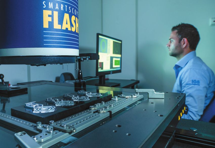
For decades, the manufacturing industry has used 2D drawings and wrestled
with interpretation and communication problems. Although processes based
on 2D drawings are deeply rooted at most companies, these drawings must be
interpreted by people, meaning errors are unavoidable.

With Model Based Definition, every step in the production process uses 3D data.
It allows one to aim for as much automated programming as possible in CAM
(MBM, Model Based Manufacturing) and metrology (MBI, Model Based Inspection).
This not only minimizes human error, but also improves product quality and
optimises every step of the production process. From design and manufacturing to
programming and inspection. These should be the main drivers to develop a new
way of working using MBD. It is integral to an Industry 4.0 strategy.

This whitepaper discusses how MBD changes the workflow in every step of the
production process. From design and Logistic Technical Engineering (LTE) to Model
Based Manufacturing , the tool shop and Model Based Inspection .

Design
Model Based Definition starts with the design department delivering an optimal
3D CAD file, called a Functional Engineering Model (FEM). The FEM needs to be a
100% accurate model of the actual steel part. Crucially, it should also include all
the Product Manufacturing Information (PMI). All information necessary to build
a tool should be added to the FEM, such as preload, venting gaps, mounting
clearances and so on. The FEM should be 100% nominal, which means no
unsymmetrical tolerances, but only +/- tolerances can be used.

                                                                                  Model Based Definition:
                       Nice-to-have or must-have for an automated, flawless industry 4.0 production environment?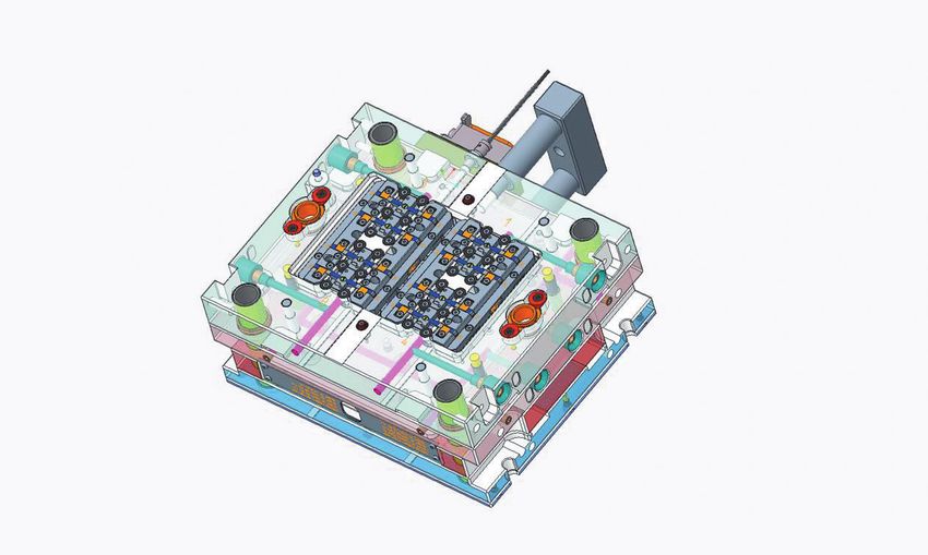
Creating a perfect FEM starts with a model of the final plastic product. It is vital
that this model is 100% accurate, as every other step in the production process
depends on it. Any inaccuracies in this product model will result in inaccuracies
in the final FEM. This means the product designer should invest sufficient time
in preparing the model of the plastic product. This file should then be delivered
in the tool maker’s preferred settings or, if possible, as a native CAD file. The
product designer can also add PMI data such as tolerances or surface finish
information to this product model, which can then also be included in the FEM.
Colour coding is one way of adding PMI data to the FEM, as is discussed below.

                         25% time
                         reductionduring
                         the design phase

This new way of working requires a shift in mind set at the design department,
as it changes the way it has operated for decades. It takes a little more time
to add the PMI to the FEM, but because 2D drawings are no longer required,
this change in approach results in a 20-25% time reduction during the
design phase. Moreover, it lays the foundation for numerous advantages in
subsequent stages of the production process, as will be discussed later in this
whitepaper.

                                                                                  Model Based Definition:
                       Nice-to-have or must-have for an automated, flawless industry 4.0 production environment?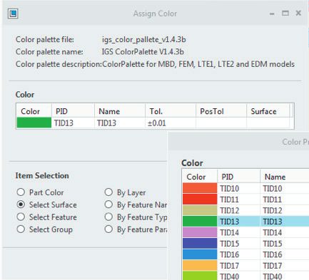
Adding PMI to the Functional Engineering Model
One way of adding Product Manufacturing Information to the FEM is to use a
colour coding system.

This colour coding system creates different appearance states (i.e. visualisations
in the CAD application) for different types of information. One appearance state
shows the colours indicating the required tolerances. Each surface area is assigned
its own colour, which corresponds with the tolerance given to the surface. A
second appearance state displays the assigned surface finishes such as EDM
texture or SPI finish.

  TID 11   ± 0.0025
  TID 12   ± 0.005
  TID 14   ± 0.01
  TID 15   ± 0.05
  TID 16   ± 0.1
  TID 17   ± 0.25

                                                                                  Model Based Definition:
                       Nice-to-have or must-have for an automated, flawless industry 4.0 production environment?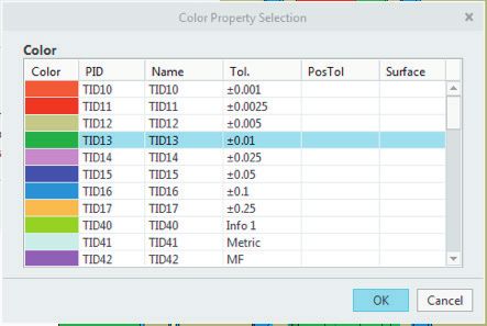
While designing the FEM, the tool designer can add the required colour (i.e.
tolerance and/or surface finish) to the model right away. As it is today, this
information is often processed days or weeks later when the 2D drawing is
prepared. This can lead to errors if the tool designer misremembers the original
idea or if the 2D drawing is created by a different member of the design team.
Immediately adding the information during the tool design removes the risk of
such errors. This reduces drawing failures by human error significantly.

Moreover, this change in approach makes it possible to start the manufacturing
phase sooner. In the old approach, the CAM programmers had to wait until the 2D
drawings had been prepared. In the new approach, the FEM has all the necessary
information to start programming.

  TID 11   ± 0.0025
  TID 12   ± 0.005
  TID 14   ± 0.01
  TID 15   ± 0.05
  TID 16   ± 0.1
  TID 17   ± 0.25

                                                                                  Model Based Definition:
                       Nice-to-have or must-have for an automated, flawless industry 4.0 production environment?
Logistic Technical Engineering with Model
Based Definition
The LTE team prepares the workflow of the manufacturing departments. They
determine the production steps necessary to manufacture the FEM, i.e. the
actual steel components used for mould assembly. To do this, the LTE team
also uses the MBD strategy and prepares 3D CAD manufacturing models. These
manufacturing models are based on and linked to the FEM. Any modifications to
the “parent” FEM will automatically be applied to “child” manufacturing models as
well. The LTE team has full control over the manufacturing models, but cannot
make any changes to the original FEM.
First, the LTE team creates a soft steel manufacturing model in which extra
allowance is added, holes are closed, extra features can be included and
so on. This means the department will create a 100% model of what will be
manufactured in soft steel before it goes into heat treatment. This model can
then be manufactured with an overall standard tolerance.
A second manufacturing model is used for hard part manufacturing. The area
which should be finished in each of the manufacturing steps is highlighted in this
model. It allows the team to add notes, additional dimensions, change tolerances
if required for manufacturing purposes and more.
A big advantage of this working method is that the workflow is captured within
the 3D CAD files and stored in the data management system covered by version
management. This allows any replacement or repeat work to be started very
quickly and ensures the exact same manufacturing strategy will be used to
create identical parts.
TID 16 ± 0.1
TID 17 ± 0.25
Model Based Definition:
Nice-to-have or must-have for an automated, flawless industry 4.0 production environment?Advantages in CAM programming
through Model Based Manufacturing
MDB saves the most time in CAM programming, through the Model Based
Manufacturing (MBM) strategy. By aiming for 75% of automated programming,
the skills of the program engineers are freed up to improve output. For example,
they can optimize the programs in order to improve quality of the most critical
parts in the tool and reduce runtime on high-volume production.
Automated programming is possible because the PMI data has been added
to the FEM during the design phase. CAM programs cannot read PMI data on
2D drawings. But through colour recognition, CAM software can determine the
tolerances that have been assigned to the holes, chambers, the outer boundary
and other features in the FEM. Using that PMI, the software can determine the
optimal standard strategy for tools to manufacture the cores and cavities.
By preparing standard strategies for milling and lathing, tool shops will be able
to use automated programming for 75% of their workload. The main reason
to do so is that human errors and deviations in strategy are minimised. These
standardized strategies will create a recognized, standardized manufacturing
method within the tool shop. All this will help to improve quality and output.
Standardized ways of working create a better workflow and allow program
engineers to put more effort in the non-standard and critical parts.
The goal of this new way of working is not to reduce the number of program
engineers, but to create more CAM programs with the same number of people.
Over the years, it has become clear that CAM capacity determines the output
of the manufacturing departments. With MBD, it should be possible to increase
output and create extra machine hours.
Automated programming
can cover up to 75% of
the workload
Model Based Definition:
Nice-to-have or must-have for an automated, flawless industry 4.0 production environment?Model Based Definition (MBD)
in the Tool Shop
As we get into the Industry 4.0 environment, we need to go paperless and supply
digital information to all departments. This is true for both the fully automated
and the non-automated activities in the tool shop. Viewable files can be created
to present all PMI data from the FEM model.
For automated activities, one can work with minimally annotated files, meaning
just a coloured 3D file showing the applied colours for tolerances and surface
finishes as well as some specific notes. In the viewable file, buttons are created
to highlight colours that indicate a tolerance or surface finish. This helps improve
readability and reduces human error. The operator can measure real dimensions
within the 3D file.
The second option is to create fully annotated files showing visual PMI data. This
tends to be easier for non-automated activities as the operators are provided
with dimensions and notes on the viewable file. This means the operators do not
need to measure in the FEM to find the manufacturing information they need.
Of course, these fully annotated files are more time-consuming to create than
minimally annotated files and will require some extra work in the design or LTE
departments.
TID 11 ± 0.0025
TID 12 ± 0.005
TID 14 ± 0.01
TID 15 ± 0.05
TID 16 ± 0.1
Model Based Definition:
Nice-to-have or must-have for an automated, flawless industry 4.0 production environment?Fast and easy programming and metrology
using Model Based Inspection (MBI)
All the advantages of CAM programming apply to metrology as well, where
automated programming also increases efficiency significantly. As in previous
steps, a 3D CAD file is prepared: the MBI file. The MBI file is also a “child” of the
FEM and it reuses the PMI data from the colour-coded FEM model. All metrology
points are added to the MBI file and standard datum plans are used to align it
with the actual steel components.
Because geometrical tolerances have been added to the FEM through colour
coding, it is no longer necessary to apply Geometric Dimensioning and
Tolerancing (GD&T) as notes. By staying within the boundaries of the geometrical
tolerances, requirements in terms of parallelism or squareness will also be
covered.
The metrology points required to measure the FEM are also added to the MBI
file. Next, the coordinate measuring machine (CMM) uses these metrology points
in the MBI file to generate the metrology reports. Because these metrology
points are also part of the FEM, they are stored in the data management system
and controlled with version management. This ensures identical metrology
output for any repeat or replacement work in the future.
Model Based Definition:
Nice-to-have or must-have for an automated, flawless industry 4.0 production environment?Model Based Definition:
Nice-to-have or must-have for an automated,
flawless industry 4.0 production environment?
If a company in the manufacturing industry wants to make a big step into
Industry 4.0, MBD is a tool they must have to make the next step in improving
the production workflow.
A number drivers are key in making the decision to start
working in an MBD environment.
Improving quality by removing the human error factor as much as possible.
• This reduces the number of rejects
• Less interruption in planning by rejects
Only using 3D files for automated programming steps in CAM and QA.
• More efficient use of programming software
• More efficient use of manufacturing equipment
• Optimized production processes
The entire production process is stored within the FEM and ready for
repeated production.
Of course, there are also downsides to implementing MBD.
Preparing the FEM requires more time as the PMI needs to be added.
More time required in the LTE department to prepare the 3D Manufacturing
models.
The risk of error when people on the shop floor need to measure directly in
the FEM instead of having the dimension available on a drawing.
These few downsides do not outweigh the benefits of using MBD.
Model Based Definition:
Nice-to-have or must-have for an automated, flawless industry 4.0 production environment?Esp 430
NL-5633 AJ Eindhoven
The Netherlands
T +31 (0)40-26 47 500
sales@igsgebojagema.nl
www.igsgebojagema.nl
From Precision to PerfectionYou can also read